


 Loading...
XV1700P
XV1700PC
SERVICE MANUAL
LIT-11616-15-37 |
5PX-28197-10 |

EAS00001
XV1700P/XV1700PC
SERVICE MANUAL
©2001 by Yamaha Motor Corporation, U.S.A. First edition, October 2001
All rights reserved.
Any reproduction or unauthorized use without the written permission of Yamaha Motor Corporation, U.S.A. is expressly prohibited.
Printed in U.S.A.
P/N LIT-11616-15-37
EAS00003
NOTICE
This manual was produced by the Yamaha Motor Company, Ltd. primarily for use by Yamaha dealers and their qualified mechanics. It is not possible to include all the knowledge of a mechanic in one manual. Therefore, anyone who uses this book to perform maintenance and repairs on Yamaha vehicles should have a basic understanding of mechanics and the techniques to repair these types of vehicles. Repair and maintenance work attempted by anyone without this knowledge is likely to render the vehicle unsafe and unfit for use.
This model has been designed and manufactured to perform within certain specifications in regard to performance and emissions. Proper service with the correct tools is necessary to ensure that the vehicle will operate as designed. If there is any question about a service procedure, it is imperative that you contact a Yamaha dealer for any service information changes that apply to this model. This policy is intended to provide the customer with the most satisfaction from his vehicle and to conform to federal environmental quality objectives.
Yamaha Motor Company, Ltd. is continually striving to improve all of its models. Modifications and significant changes in specifications or procedures will be forwarded to all authorized Yamaha dealers and will appear in future editions of this manual where applicable.
NOTE:
Designs and specifications are subject to change without notice.
EAS00004
IMPORTANT MANUAL INFORMATION
Particularly important information is distinguished in this manual by the following.
The Safety Alert Symbol means ATTENTION! BECOME ALERT! YOUR SAFETY IS INVOLVED!
 WARNING Failure to follow WARNING instructions could result in severe injury or death to the motorcycle operator, a bystander or a person checking or repairing the motorcycle.


 CAUTION:

 A CAUTION indicates special precautions that must be taken to avoid damage to the motorcycle.
NOTE: A NOTE provides key information to make procedures easier or clearer.

EAS00007
HOW TO USE THIS MANUAL
This manual is intended as a handy, easy-to-read reference book for the mechanic. Comprehensive explanations of all installation, removal, disassembly, assembly, repair and check procedures are laid out with the individual steps in sequential order.
1 The manual is divided into chapters. An abbreviation and symbol in the upper right corner of each page indicate the current chapter.
Refer to “SYMBOLS”.
2 Each chapter is divided into sections. The current section title is shown at the top of each page, except in Chapter 3 (“PERIODIC CHECKS AND ADJUSTMENTS”), where the sub-section title(s) appears.
3Sub-section titles appear in smaller print than the section title.
4To help identify parts and clarify procedure steps, there are exploded diagrams at the start of each removal and disassembly section.
5Numbers are given in the order of the jobs in the exploded diagram. A circled number indicates a disassembly step.
6Symbols indicate parts to be lubricated or replaced. Refer to “SYMBOLS”.
7A job instruction chart accompanies the exploded diagram, providing the order of jobs, names of parts, notes in jobs, etc.
8Jobs requiring more information (such as special tools and technical data) are described sequentially.
1 |
|
|
2 |
GEN |
|
|
SPEC |
INFO |
|
|
|
|
|
|
|
3 |
|
|
4 |
CHK |
|
|
CHAS |
ADJ |
|
|
|
|
|
|
|
5 |
|
|
6 |
ENG |
|
|
FI |
7 |
|
|
8 |
ELEC – |
+ |
|
TRBL |
|
|
|
SHTG |
9 |
|
|
0 |
A |
|
|
B |
C |
|
|
D |
T |
|
|
|
. |
|
|
|
R |
|
|
|
. |
|
|
|
E |
|
|
F |
G |
H |
|
I |
E |
|
G |
M |
J |
K |
|
L |
B |
|
LS |
M |
M |
|
|
N |
LT |
|
|
New |
|
|
|
EAS00009
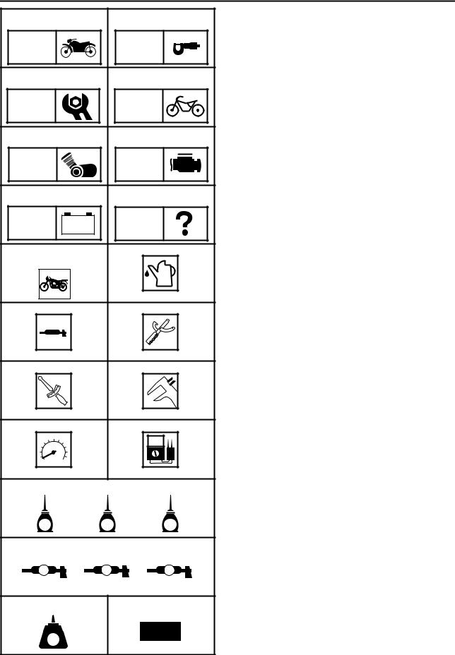
SYMBOLS
The following symbols are not relevant to every vehicle. Symbols 1 to 8 indicate the subject of each chapter.
1 General information
2Specifications
3Periodic checks and adjustments
4Chassis
5Engine
6Fuel injection system
7Electrical system
8Troubleshooting
Symbols 9 to F indicate the following.
9 Serviceable with engine mounted
0 Filling fluid
ALubricant
BSpecial tool
CTightening torque
DWear limit, clearance
EEngine speed
FElectrical data
Symbols G to L in the exploded diagrams indicate the types of lubricants and lubrication points.
G Engine oil
H Gear oil
IMolybdenum-disulfide oil
JWheel-bearing grease
KLithium-soap-based grease
LMolybdenum-disulfide grease
Symbols M to N in the exploded diagrams indicate the following.
MApply locking agent (LOCTITE®)
NReplace the part
EAS00013
TABLE OF CONTENTS
GENERAL INFORMATION |
GEN |
1 |
|
INFO |
SPECIFICATIONS
SPEC 2
PERIODIC CHECKS AND |
CHKADJ 3 |
ADJUSTMENTS |
CHASSIS |
4 |
CHAS |
ENGINE
ENG 5
FUEL INJECTION SYSTEM |
|
|
|
|
|
|
|
|
FI |
6 |
|||||||
|
||||||||
|
|
|
|
|
|
|
|
|
|
|
|
|
|
|
|
|
|
|
|
|
– |
+ |
|
|
||
ELECTRICAL SYSTEM |
|
|
|
|
|
|
|
|
|
|
|
|
|
|
|
||
ELEC |
7 |
|||||||
|
||||||||
TROUBLESHOOTING |
|
|
|
|
TRBL |
8 |
|||
|
SHTG |
|||

CONTENTS
CHAPTER 1
GENERAL INFORMATION
MOTORCYCLE IDENTIFICATION .................................................................. |
1-1 |
VEHICLE IDENTIFICATION NUMBER ..................................................... |
1-1 |
MODEL LABEL.......................................................................................... |
1-1 |
FEATURES ...................................................................................................... |
1-2 |
OUTLINE ................................................................................................... |
1-2 |
FI SYSTEM ................................................................................................ |
1-3 |
COMPONENTS ......................................................................................... |
1-5 |
FUEL INJECTION SYSTEM .................................................................... |
1-17 |
FIRST IDLE CONTROL SYSTEM ........................................................... |
1-28 |
COMPONENTS ....................................................................................... |
1-29 |
IMPORTANT INFORMATION........................................................................ |
1-32 |
PREPARATION FOR REMOVAL AND DISASSEMBLY ......................... |
1-32 |
REPLACEMENT PARTS ......................................................................... |
1-32 |
GASKETS, OIL SEALS AND O-RINGS .................................................. |
1-32 |
LOCK WASHERS/PLATES AND COTTER PINS ................................... |
1-33 |
BEARINGS AND OIL SEALS .................................................................. |
1-33 |
CIRCLIPS ................................................................................................ |
1-33 |
CHECKING THE CONNECTIONS ................................................................ |
1-34 |
SPECIAL TOOLS .......................................................................................... |
1-35 |
CHAPTER 2 |
|
SPECIFICATIONS |
|
GENERAL SPECIFICATIONS......................................................................... |
2-1 |
ENGINE SPECIFICATIONS ........................................................................... |
2-2 |
CHASSIS SPECIFICATIONS ........................................................................ |
2-13 |
ELECTRICAL SPECIFICATIONS ................................................................. |
2-17 |
CONVERSION TABLE .................................................................................. |
2-20 |
GENERAL TIGHTENING TORQUE SPECIFICATIONS ............................... |
2-20 |

TIGHTENING TORQUES .............................................................................. |
2-21 |
ENGINE TIGHTENING TORQUES ......................................................... |
2-21 |
CHASSIS TIGHTENING TORQUES ....................................................... |
2-24 |
LUBRICATION POINTS AND LUBRICANT TYPES..................................... |
2-27 |
ENGINE .................................................................................................. |
2-27 |
CHASSIS ................................................................................................ |
2-28 |
ENGINE OIL LUBRICATION CHART ........................................................... |
2-29 |
ENGINE OIL FLOW DIAGRAMS .................................................................. |
2-30 |
TRANSFER GEAR OIL FLOW DIAGRAMS ................................................. |
2-34 |
CABLE ROUTING ......................................................................................... |
2-36 |
CHAPTER 3 |
|
PERIODIC CHECKS AND ADJUSTMENTS |
|
INTRODUCTION.............................................................................................. |
3-1 |
PERIODIC MAINTENANCE CHART |
|
FOR THE EMISSION CONTROL SYSTEM ................................................... |
3-1 |
GENERAL MAINTENANCE AND LUBRICATION CHART ............................ |
3-2 |
SEAT AND SIDE COVERS ............................................................................. |
3-4 |
HEADLIGHT AND METER ASSEMBLIES...................................................... |
3-5 |
BATTERY ........................................................................................................ |
3-6 |
FUEL TANK ..................................................................................................... |
3-7 |
AIR FILTER CASE........................................................................................... |
3-8 |
SILENCER AIR FILTER CASE ....................................................................... |
3-9 |

ENGINE.......................................................................................................... |
3-11 |
ADJUSTING THE VALVE CLEARANCE................................................. |
3-11 |
SYNCHRONIZING THE THROTTLE BODIES ........................................ |
3-15 |
ADJUSTING THE ENGINE IDLING SPEED ........................................... |
3-17 |
ADJUSTING THE THROTTLE CABLE FREE PLAY............................... |
3-18 |
CHECKING THE SPARK PLUGS ........................................................... |
3-20 |
CHECKING THE IGNITION TIMING ....................................................... |
3-22 |
MEASURING THE COMPRESSION PRESSURE .................................. |
3-23 |
CHECKING THE ENGINE OIL LEVEL .................................................... |
3-26 |
CHANGING THE ENGINE OIL................................................................ |
3-27 |
MEASURING THE ENGINE OIL PRESSURE ........................................ |
3-31 |
CHECKING THE TRANSFER GEAR OIL LEVEL ................................... |
3-32 |
CHANGING THE TRANSFER GEAR OIL ............................................... |
3-33 |
ADJUSTING THE CLUTCH CABLE FREE PLAY ................................... |
3-35 |
CLEANING THE AIR FILTER ELEMENTS ............................................. |
3-36 |
CHECKING THE THROTTLE BODY JOINTS......................................... |
3-37 |
CHECKING THE FUEL HOSES .............................................................. |
3-37 |
CHECKING THE CYLINDER HEAD BREATHER HOSE AND |
|
OIL TANK BREATHER HOSE................................................................ |
3-38 |
CHECKING THE EXHAUST SYSTEM .................................................... |
3-39 |
CHASSIS ....................................................................................................... |
3-40 |
ADJUSTING THE FRONT BRAKE.......................................................... |
3-40 |
ADJUSTING THE REAR BRAKE ............................................................ |
3-41 |
CHECKING THE BRAKE FLUID LEVEL ................................................. |
3-42 |
CHECKING THE FRONT BRAKE PADS ................................................ |
3-43 |
CHECKING THE REAR BRAKE PADS................................................... |
3-43 |
ADJUSTING THE REAR BRAKE LIGHT SWITCH ................................. |
3-44 |
CHECKING THE FRONT AND REAR BRAKE HOSES .......................... |
3-44 |
BLEEDING THE HYDRAULIC BRAKE SYSTEM.................................... |
3-45 |
ADJUSTING THE SHIFT PEDAL ............................................................ |
3-47 |
ADJUSTING THE DRIVE BELT SLACK ................................................. |
3-47 |
CHECKING AND ADJUSTING THE STEERING HEAD ......................... |
3-50 |
CHECKING THE FRONT FORK ............................................................. |
3-52 |
ADJUSTING THE FRONT FORK LEGS ................................................. |
3-53 |
ADJUSTING THE REAR SHOCK ABSORBER ASSEMBLY .................. |
3-54 |
CHECKING THE TIRES .......................................................................... |
3-55 |
CHECKING THE WHEELS ..................................................................... |
3-58 |
CHECKING AND LUBRICATING THE CABLES..................................... |
3-58 |
LUBRICATING THE LEVERS AND PEDALS ......................................... |
3-59 |
LUBRICATING THE SIDESTAND ........................................................... |
3-59 |
LUBRICATING THE REAR SUSPENSION ............................................. |
3-59 |
ELECTRICAL SYSTEM................................................................................. |
3-60 |
CHECKING AND CHARGING THE BATTERY ....................................... |
3-60 |
CHECKING THE FUSES......................................................................... |
3-65 |
REPLACING THE HEADLIGHT BULB .................................................... |
3-68 |
ADJUSTING THE HEADLIGHT BEAM ................................................... |
3-69 |

INSTRUMENT FUNCTIONS.......................................................................... |
3-70 |
ODOMETER AND TRIPMETER.............................................................. |
3-70 |
ADJUSTING THE METER LIGHT ........................................................... |
3-71 |
ADJUSTING THE CLOCK ....................................................................... |
3-71 |
CHAPTER 4
CHASSIS
FRONT WHEEL AND BRAKE DISCS ............................................................ |
4-1 |
REMOVING THE FRONT WHEEL ............................................................ |
4-4 |
CHECKING THE FRONT WHEEL ............................................................ |
4-4 |
CHECKING THE BRAKE DISCS .............................................................. |
4-6 |
INSTALLING THE FRONT WHEEL .......................................................... |
4-7 |
ADJUSTING THE FRONT WHEEL STATIC BALANCE............................ |
4-9 |
REAR WHEEL, BRAKE DISC, AND REAR WHEEL PULLEY..................... |
4-11 |
REMOVING THE REAR WHEEL ............................................................ |
4-17 |
CHECKING THE REAR WHEEL ............................................................. |
4-17 |
CHECKING THE REAR WHEEL DRIVE HUB ........................................ |
4-18 |
CHECKING AND REPLACING THE REAR WHEEL PULLEY................ |
4-18 |
ASSEMBLING THE REAR WHEEL ........................................................ |
4-18 |
INSTALLING THE REAR WHEEL ........................................................... |
4-19 |
ADJUSTING THE REAR WHEEL STATIC BALANCE ............................ |
4-22 |
FRONT AND REAR BRAKES....................................................................... |
4-23 |
FRONT BRAKE PADS ............................................................................ |
4-23 |
REAR BRAKE PADS ............................................................................... |
4-24 |
REPLACING THE FRONT BRAKE PADS .............................................. |
4-25 |
REPLACING THE REAR BRAKE PADS ................................................. |
4-27 |
FRONT BRAKE MASTER CYLINDER .................................................... |
4-30 |
REAR BRAKE MASTER CYLINDER ...................................................... |
4-33 |
REMOVING THE FRONT BRAKE MASTER CYLINDER ....................... |
4-37 |
REMOVING THE REAR BRAKE MASTER CYLINDER.......................... |
4-37 |
CHECKING THE FRONT AND REAR BRAKE MASTER CYLINDERS ..4-37 |
|
ASSEMBLING AND INSTALLING THE FRONT BRAKE |
|
MASTER CYLINDER.............................................................................. |
4-38 |
ASSEMBLING AND INSTALLING THE REAR BRAKE |
|
MASTER CYLINDER.............................................................................. |
4-41 |
FRONT BRAKE CALIPERS .................................................................... |
4-43 |
REAR BRAKE CALIPER ......................................................................... |
4-45 |
DISASSEMBLING THE FRONT BRAKE CALIPERS .............................. |
4-47 |
DISASSEMBLING THE REAR BRAKE CALIPER................................... |
4-48 |
CHECKING THE FRONT AND REAR BRAKE CALIPERS..................... |
4-49 |
ASSEMBLING AND INSTALLING THE FRONT BRAKE CALIPERS ..... |
4-50 |
ASSEMBLING AND INSTALLING THE REAR BRAKE CALIPER .......... |
4-52 |
FRONT FORK................................................................................................ |
4-55 |
REMOVING THE FRONT FORK LEGS .................................................. |
4-58 |
DISASSEMBLING THE FRONT FORK LEGS ........................................ |
4-58 |
CHECKING THE FRONT FORK LEGS................................................... |
4-60 |
ASSEMBLING THE FRONT FORK LEGS .............................................. |
4-62 |
INSTALLING THE FRONT FORK LEGS................................................. |
4-67 |
HANDLEBAR................................................................................................. |
4-69 |
REMOVING THE HANDLEBAR .............................................................. |
4-71 |
CHECKING THE HANDLEBAR............................................................... |
4-71 |
INSTALLING THE HANDLEBAR............................................................. |
4-71 |
STEERING HEAD.......................................................................................... |
4-75 |
REMOVING THE LOWER BRACKET ..................................................... |
4-77 |
CHECKING THE STEERING HEAD ....................................................... |
4-77 |
INSTALLING THE STEERING HEAD ..................................................... |
4-78 |
REAR SHOCK ABSORBER AND SWINGARM ........................................... |
4-80 |
HANDLING THE REAR SHOCK ABSORBER ........................................ |
4-84 |
DISPOSING OF A REAR SHOCK ABSORBER |
|
AND GAS CYLINDER............................................................................. |
4-84 |
REMOVING THE REAR SHOCK ABSORBER AND SWINGARM.......... |
4-85 |
CHECKING THE REAR SHOCK ABSORBER ........................................ |
4-86 |
CHECKING THE RELAY ARM AND CONNECTING ARM ..................... |
4-86 |
CHECKING THE SWINGARM ................................................................ |
4-86 |
INSTALLING THE REAR SHOCK ABSORBER AND SWINGARM ........ |
4-87 |
DRIVE BELT AND DRIVE SPROCKET ........................................................ |
4-89 |
REMOVING THE DRIVE BELT AND DRIVE SPROCKET...................... |
4-90 |
CHECKING THE DRIVE BELT................................................................ |
4-90 |
INSTALLING THE DRIVE BELT AND DRIVE SPROCKET .................... |
4-91 |

CHAPTER 5
ENGINE
ENGINE............................................................................................................ |
5-1 |
INSTALLING THE ENGINE ....................................................................... |
5-9 |
INSTALLING THE MUFFLER AND EXHAUST PIPES............................ |
5-10 |
ROCKER ARMS, PUSH RODS AND VALVE LIFTERS .............................. |
5-11 |
REMOVING THE ROCKER ARMS, PUSH RODS AND |
|
VALVE LIFTERS..................................................................................... |
5-16 |
CHECKING THE ROCKER ARMS AND ROCKER ARM SHAFTS......... |
5-16 |
CHECKING THE ROCKER ARM BASES ............................................... |
5-18 |
CHECKING THE PUSH RODS ............................................................... |
5-18 |
CHECKING THE VALVE LIFTERS AND VALVE LIFTER CASES.......... |
5-18 |
BLEEDING A VALVE LIFTER ................................................................. |
5-19 |
CHECKING THE PUSH ROD COVER .................................................... |
5-21 |
INSTALLING THE VALVE LIFTERS ....................................................... |
5-21 |
INSTALLING THE ROCKER ARMS AND PUSH RODS ......................... |
5-22 |
INSTALLING THE CYLINDER HEAD COVERS ..................................... |
5-23 |
INSTALLING THE CAMSHAFT SPROCKET COVER AND |
|
ENGINE LEFT SIDE COVER ................................................................. |
5-23 |
CAMSHAFTS................................................................................................. |
5-25 |
REMOVING THE CAMSHAFTS .............................................................. |
5-27 |
CHECKING THE CAMSHAFTS .............................................................. |
5-28 |
CHECKING THE DECOMPRESSION SYSTEM ..................................... |
5-30 |
CHECKING THE OIL DELIVERY PIPE ................................................... |
5-30 |
INSTALLING THE CAMSHAFTS ............................................................ |
5-31 |
CYLINDER HEADS ....................................................................................... |
5-34 |
REMOVING THE CYLINDER HEADS .................................................... |
5-36 |
CHECKING THE CYLINDER HEADS ..................................................... |
5-36 |
CHECKING THE OIL DELIVERY PIPE ................................................... |
5-37 |
INSTALLING THE CYLINDER HEAD ..................................................... |
5-37 |
VALVES AND VALVE SPRINGS ................................................................. |
5-39 |
REMOVING THE VALVES ...................................................................... |
5-40 |
CHECKING THE VALVES AND VALVE GUIDES................................... |
5-41 |
CHECKING THE VALVE SEATS ............................................................ |
5-43 |
CHECKING THE VALVE SPRINGS ........................................................ |
5-46 |
INSTALLING THE VALVES..................................................................... |
5-47 |
CYLINDERS AND PISTONS ......................................................................... |
5-49 |
REMOVING THE CYLINDERS AND PISTONS ...................................... |
5-50 |
CHECKING THE CYLINDERS AND PISTONS....................................... |
5-51 |
CHECKING THE PISTON RINGS ........................................................... |
5-52 |
CHECKING THE PISTON PINS .............................................................. |
5-53 |
INSTALLING THE PISTONS AND CYLINDERS..................................... |
5-54 |

CLUTCH......................................................................................................... |
5-56 |
CLUTCH COVER .................................................................................... |
5-56 |
CLUTCH .................................................................................................. |
5-59 |
REMOVING THE CLUTCH ..................................................................... |
5-61 |
REMOVING THE PRIMARY DRIVE GEAR ............................................ |
5-62 |
CHECKING THE FRICTION PLATES ..................................................... |
5-62 |
CHECKING THE CLUTCH PLATES ....................................................... |
5-62 |
CHECKING THE CLUTCH PLATE SPRING ........................................... |
5-63 |
CHECKING THE CLUTCH HOUSING .................................................... |
5-63 |
CHECKING THE CLUTCH BOSS ........................................................... |
5-63 |
CHECKING THE PRESSURE PLATE .................................................... |
5-64 |
CHECKING THE PULL LEVER SHAFT AND PULL ROD....................... |
5-64 |
CHECKING THE PRIMARY DRIVE ........................................................ |
5-64 |
INSTALLING THE CRANKSHAFT POSITION SENSOR AND |
|
PULL LEVER SHAFT ............................................................................. |
5-64 |
INSTALLING THE PRIMARY DRIVE GEAR ........................................... |
5-65 |
INSTALLING THE CLUTCH .................................................................... |
5-66 |
SHIFT SHAFT AND STOPPER LEVER ........................................................ |
5-70 |
CHECKING THE SHIFT SHAFT ............................................................. |
5-71 |
CHECKING THE STOPPER LEVER....................................................... |
5-71 |
INSTALLING THE STOPPER LEVER AND SHIFT SHAFT .................... |
5-71 |
GENERATOR AND STARTER CLUTCH...................................................... |
5-73 |
STATOR COIL ASSEMBLY .................................................................... |
5-73 |
GENERATOR AND STARTER CLUTCH ................................................ |
5-75 |
REMOVING THE GENERATOR ............................................................. |
5-76 |
CHECKING THE STARTER CLUTCH .................................................... |
5-76 |
INSTALLING THE GENERATOR ............................................................ |
5-77 |
TRANSFER GEAR CASE ............................................................................. |
5-79 |
FUEL PUMP ............................................................................................ |
5-82 |
REMOVING THE FUEL PUMP ............................................................... |
5-83 |
INSTALL THE FUEL PUMP .................................................................... |
5-83 |
SUB FUEL TANK..................................................................................... |
5-84 |
REMOVING THE MIDDLE DRIVEN SHAFT ........................................... |
5-88 |
CHECKING THE MIDDLE DRIVE ........................................................... |
5-88 |
CHECKING THE OIL STRAINER............................................................ |
5-89 |
CHECKING THE OIL PUMP ................................................................... |
5-89 |
CHECKING THE OIL PIPE...................................................................... |
5-90 |
ASSEMBLING THE OIL PUMP ............................................................... |
5-90 |
INSTALLING THE TRANSFER GEAR CASE ......................................... |
5-91 |

CRANKCASE ................................................................................................ |
5-93 |
DISASSEMBLING THE CRANKCASE .................................................... |
5-96 |
CHECKING THE CRANKCASE .............................................................. |
5-97 |
CHECKING THE BEARINGS AND OIL SEALS ...................................... |
5-98 |
CHECKING THE OIL DELIVERY PIPE ................................................... |
5-98 |
CHECKING THE ENGINE OIL PUMP DRIVE......................................... |
5-98 |
ASSEMBLING THE CRANKCASE .......................................................... |
5-99 |
ENGINE OIL PUMP ..................................................................................... |
5-102 |
CHECKING THE OIL PUMP ................................................................. |
5-105 |
CHECKING THE RELIEF VALVE ......................................................... |
5-105 |
CHECKING THE OIL STRAINER.......................................................... |
5-106 |
ASSEMBLING THE OIL PUMP ............................................................. |
5-106 |
INSTALLING THE OIL PUMP ............................................................... |
5-107 |
INSTALLING THE OIL STRAINER........................................................ |
5-108 |
CRANKSHAFT AND CONNECTING RODS ............................................... |
5-109 |
REMOVING THE CRANKSHAFT.......................................................... |
5-110 |
REMOVING THE CONNECTING RODS............................................... |
5-110 |
CHECKING THE CRANKSHAFT AND CONNECTING RODS ............. |
5-110 |
INSTALLING THE CONNECTING RODS ............................................. |
5-116 |
INSTALLING THE CRANKSHAFT ........................................................ |
5-118 |
TRANSMISSION.......................................................................................... |
5-119 |
CHECKING THE SHIFT FORKS ........................................................... |
5-122 |
CHECKING THE SHIFT DRUM ASSEMBLY ........................................ |
5-123 |
CHECKING THE TRANSMISSION ....................................................... |
5-123 |
INSTALLING THE TRANSMISSION ..................................................... |
5-124 |
INSTALLING THE SHIFT FORKS AND SHIFT DRUM ASSEMBLY..... |
5-124 |
CHAPTER 6 |
|
FUEL INJECTION SYSTEM |
|
FUEL INJECTION SYSTEM ............................................................................ |
6-1 |
WIRING DIAGRAM.................................................................................... |
6-2 |
ECU’S SELF-DIAGNOSTIC FUNCTION ................................................... |
6-4 |
SUBSTITUTE CHARACTERISTICS OPERATION CONTROL |
|
(FAIL-SAFE ACTION)............................................................................... |
6-8 |
TROUBLESHOOTING............................................................................... |
6-9 |
THROTTLE BODIES ............................................................................... |
6-37 |
CHECKING THE INJECTOR................................................................... |
6-41 |
CHECKING THE THROTTLE BODY ...................................................... |
6-41 |
CHECKING THE FUEL PUMP AND |
|
PRESSURE REGULATOR OPERATION............................................... |
6-42 |

AIR INDUCTION SYSTEM ............................................................................ |
6-43 |
AIR INJECTION ....................................................................................... |
6-43 |
AIR CUT-OFF VALVE ............................................................................. |
6-43 |
AIR CUT-OFF VALVE ASSEMBLY AND |
|
AIR INDUCTION SYSTEM HOSES........................................................ |
6-44 |
REED VALVES........................................................................................ |
6-45 |
CHECKING THE PRESSURE REGULATOR.......................................... |
6-46 |
CHECKING THE AIR INDUCTION SYSTEM .......................................... |
6-46 |
CHAPTER 7
ELECTRICAL SYSTEM
ELECTRICAL COMPONENTS........................................................................ |
7-1 |
ARRANGEMENT OF THE ELECTRICAL COMPONENTS AND |
|
COUPLERS .................................................................................................... |
7-3 |
CHECKING SWITCH CONTINUITY ................................................................ |
7-8 |
CHECKING THE SWITCHES ........................................................................ |
7-10 |
CHECKING THE BULBS AND BULB SOCKETS ........................................ |
7-12 |
TYPES OF BULBS .................................................................................. |
7-12 |
CHECKING THE CONDITION OF THE BULBS...................................... |
7-12 |
CHECKING THE CONDITION OF THE BULB SOCKETS...................... |
7-14 |
CHECKING THE LEDs ............................................................................ |
7-15 |
IGNITION SYSTEM........................................................................................ |
7-16 |
CIRCUIT DIAGRAM ................................................................................ |
7-16 |
TROUBLESHOOTING............................................................................. |
7-17 |
ELECTRIC STARTING SYSTEM .................................................................. |
7-22 |
CIRCUIT DIAGRAM ................................................................................ |
7-22 |
STARTING CIRCUIT CUT-OFF SYSTEM OPERATION ........................ |
7-23 |
TROUBLESHOOTING............................................................................. |
7-24 |
STARTER MOTOR ........................................................................................ |
7-28 |
CHECKING THE STARTER MOTOR ..................................................... |
7-31 |
ASSEMBLING THE STARTER MOTOR ................................................. |
7-33 |
CHARGING SYSTEM .................................................................................... |
7-35 |
CIRCUIT DIAGRAM ................................................................................ |
7-35 |
TROUBLESHOOTING............................................................................. |
7-36 |

LIGHTING SYSTEM ...................................................................................... |
7-38 |
CIRCUIT DIAGRAM ................................................................................ |
7-38 |
TROUBLESHOOTING............................................................................. |
7-39 |
CHECKING THE LIGHTING SYSTEM .................................................... |
7-40 |
SIGNALING SYSTEM.................................................................................... |
7-44 |
CIRCUIT DIAGRAM ................................................................................ |
7-44 |
TROUBLESHOOTING............................................................................. |
7-46 |
CHECKING THE SIGNALING SYSTEM ................................................. |
7-47 |
FUEL INJECTION SYSTEM .......................................................................... |
7-54 |
CIRCUIT DIAGRAM ................................................................................ |
7-54 |
TROUBLESHOOTING............................................................................. |
7-56 |
CHECKING THE FUEL PUMP ................................................................ |
7-64 |
CHECKING AND ADJUSTING |
|
THE THROTTLE POSITION SENSOR .................................................. |
7-64 |
CHAPTER 8 |
|
TROUBLESHOOTING |
|
STARTING FAILURES .................................................................................... |
8-1 |
ENGINE ..................................................................................................... |
8-1 |
FUEL SYSTEM .......................................................................................... |
8-1 |
ELECTRICAL SYSTEMS .......................................................................... |
8-2 |
INCORRECT ENGINE IDLING SPEED........................................................... |
8-2 |
ENGINE ..................................................................................................... |
8-2 |
FUEL SYSTEM .......................................................................................... |
8-2 |
ELECTRICAL SYSTEMS .......................................................................... |
8-2 |
POOR MEDIUM-AND-HIGH-SPEED PERFORMANCE ................................. |
8-3 |
ENGINE ..................................................................................................... |
8-3 |
FUEL SYSTEM .......................................................................................... |
8-3 |
FAULTY GEAR SHIFTING .............................................................................. |
8-3 |
SHIFTING IS DIFFICULT .......................................................................... |
8-3 |
SHIFT PEDAL DOES NOT MOVE ............................................................ |
8-3 |
JUMPS OUT OF GEAR ............................................................................. |
8-3 |
FAULTY CLUTCH ........................................................................................... |
8-3 |
CLUTCH SLIPS ......................................................................................... |
8-3 |
CLUTCH DRAGS ...................................................................................... |
8-3 |

OVERHEATING ............................................................................................... |
8-4 |
ENGINE ..................................................................................................... |
8-4 |
FUEL SYSTEM .......................................................................................... |
8-4 |
CHASSIS ................................................................................................... |
8-4 |
ELECTRICAL SYSTEMS .......................................................................... |
8-4 |
POOR BRAKING PERFORMANCE................................................................ |
8-4 |
FAULTY FRONT FORK LEGS........................................................................ |
8-4 |
LEAKING OIL ............................................................................................ |
8-4 |
MALFUNCTION ......................................................................................... |
8-4 |
UNSTABLE HANDLING.................................................................................. |
8-5 |
FAULTY LIGHTING OR SIGNALING SYSTEM.............................................. |
8-6 |
HEADLIGHT DOES NOT COME ON ........................................................ |
8-6 |
HEADLIGHT BULB BURNT OUT .............................................................. |
8-6 |
TAIL/BRAKE LIGHT DOES NOT COME ON ............................................ |
8-6 |
TAIL/BRAKE LIGHT LED BURNT OUT .................................................... |
8-6 |
TURN SIGNAL DOES NOT COME ON..................................................... |
8-6 |
TURN SIGNAL BLINKS SLOWLY ............................................................. |
8-6 |
TURN SIGNAL REMAINS LIT ................................................................... |
8-6 |
TURN SIGNAL BLINKS QUICKLY ............................................................ |
8-6 |
HORN DOES NOT SOUND ...................................................................... |
8-6 |
GEN
MOTORCYCLE IDENTIFICATION INFO
EAS00014
GENERAL INFORMATION
MOTORCYCLE IDENTIFICATION
EAS00017
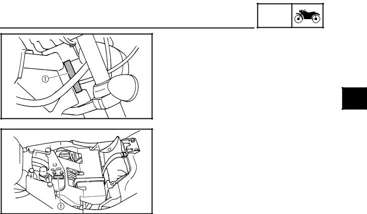
VEHICLE IDENTIFICATION NUMBER
The vehicle identification number 1 is stamped into the right side of the steering head pipe.
EAS00018
MODEL LABEL
The model label 1 is affixed to the frame. This information will be needed to order spare parts.
1 |
1 - 1
FEATURES
FEATURES
OUTLINE
GEN INFO
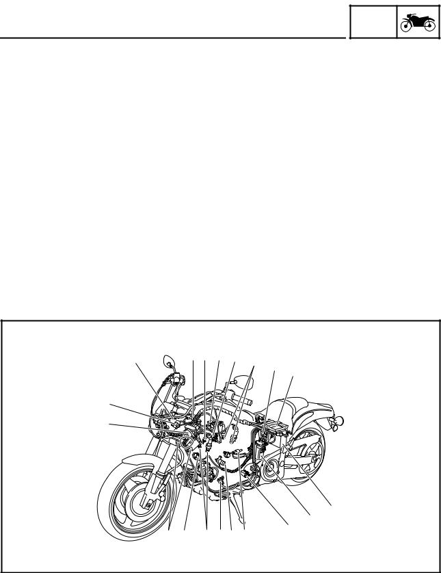
The main function of a fuel supply system is to provide fuel to the combustion chamber at the optimum air-fuel ratio in accordance with the engine operating conditions and the atmospheric temperature.
In the conventional carburetor system, the air-fuel ratio of the mixture that is supplied to the combustion chamber is created by the volume of the intake air and the fuel that is metered by the jet that is used in the respective chamber.
Despite the same volume of intake air, the fuel volume requirement varies by the engine operating conditions, such as acceleration, deceleration, or operating under a heavy load. Carburetors that meter the fuel through the use of jets have been provided with various auxiliary devices, so that an optimum air-fuel ratio can be achieved to accommodate the constant changes in the operating conditions of the engine.
As the requirements for the engine to deliver more performance and cleaner exhaust gases increase, it becomes necessary to control the air-fuel ratio in a more precise and finely tuned manner. To accommodate this need, this model has adopted an electronically controlled fuel injection (FI) system, in place of the conventional carburetor system. This system can achieve an optimum air-fuel ratio required by the engine at all times by using a microprocessor that regulates the fuel injection volume according to the engine operating conditions detected by various sensors.
The adoption of the FI system has resulted in a highly precise fuel supply, improved engine response, better fuel economy, and reduced exhaust emissions.
3 |
45 6 7 |
8 9 |
|
|
|
0 |
|
|
|
|
2
1
A
B
C
H G 8 FE D
1 Liner control valve |
7 Throttle position sensor |
C Lean angle cut-off switch |
2 Intake air pressure sensor 2 |
8 Spark plug |
D Oil temperature sensor |
3 Intake air temperature sensor |
9 Relay unit |
E Decompression solenoid |
4 Intake air pressure sensor 1 |
0 ECU |
F Crankshaft position sensor |
5 Engine temperature sensor |
A Battery |
G Cylinder identification sensor |
6 Atmospheric pressure sensor |
B Fuel pump |
H Ignition coil |
1 - 2

FEATURES
FI SYSTEM
GEN INFO
The fuel pump delivers fuel to the injector via the fuel filter. The pressure regulator maintains the fuel pressure that is applied to the injector at only 2.55 kg/cm2 higher than the intake manifold pressure. Accordingly, when the energizing signal from the ECU energizes the injector, the fuel passage opens, causing the fuel to be injected into the intake manifold only during the time the passage remains open. Therefore, the longer the length of time the injector is energized (injection duration), the greater the volume of fuel that is supplied. Conversely, the shorter the length of time the injector is energized (injection duration), the lesser the volume of fuel that is supplied.
The injection duration and the injection timing are controlled by the ECU. Signals that are input from the throttle position sensor, crankshaft position sensor, intake air pressure sensor, atmospheric pressure sensor, intake temperature sensor, engine temperature sensor, and oil temperature sensor enable the ECU to determine the injection duration. The injection timing is determined through the signals from the crankshaft position sensor and the cylinder identification sensor. As a result, the volume of fuel that is required by the engine can be supplied at all times in accordance with the driving conditions.
Illustration is for reference only.
2
È |
1 |
|
#2 #1 |
||
|
||
A 3 |
É |
|
5 |
||
|
||
4 |
7 |
|
|
9 |
|
6 |
8 Ê |
|
|
0 B
B
1 Fuel pump |
7 Intake air pressure sensor |
È Fuel system |
2 Pressure regulator |
8 ECU |
É Air system |
3 Fuel injector |
9 Atmospheric pressure sensor |
Ê Control system |
4 Throttle body |
0 Engine temperature sensor |
|
5 Intake temperature sensor |
A Cylinder identification sensor |
|
6 Throttle position sensor |
B Crankshaft position sensor |
|
1 - 3
FEATURES
Fuel control block
The fuel control block consists of the following main components:
GEN INFO
|
Component |
Function |
|
|
|
Control block |
ECU |
Total FI system control |
|
|
|
|
Throttle body |
Air volume control |
|
|
|
|
Pressure regulator |
Fuel pressure adjustment |
|
|
|
Sensor block |
Intake air pressure sensor |
Intake air pressure detection |
|
|
|
|
Atmospheric pressure sensor |
Atmospheric pressure detection |
|
|
|
|
Engine temperature sensor |
Engine temperature detection |
|
|
|
|
Intake temperature sensor |
Intake temperature detection |
|
|
|
|
Throttle position sensor |
Throttle angle detection |
|
|
|
|
Oil temperature sensor |
Engine oil temperature detection |
|
|
|
|
Cylinder identification sensor |
Reference position detection |
|
|
|
|
Crankshaft position sensor |
Crankshaft position detection and engine |
|
|
RPM detection |
|
|
|
|
Speed sensor |
Speed detection |
|
|
|
Actuator block |
Injector |
Fuel injection |
|
|
|
|
Fuel pump |
Fuel feed |
|
|
|
|
Air Induction system, air cut valve |
Induction of secondary air |
|
|
|
|
Liner control valve |
First idle control (see page 1-28) |
|
|
|
An FI warning light is provided on meter panel.
1 - 4
FEATURES
COMPONENTS
ECU (Electronic Control Unit)
GEN INFO
The ECU is mounted underneath the seat, above the battery box. The main functions of the ECU are ignition control, fuel control, self-diagnosis, and load control.
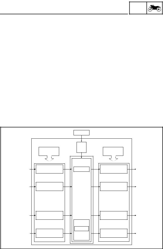
•ECU’s internal construction and functions
The main components and functions of the ECU can be broadly divided into the following four items:
A.Power supply circuit
The power supply circuit obtains power from the battery (12 V) to supply the power (more than 5 V) that is required for operating the ECU.
B.Input interface circuits
The input interface circuits convert the signals output by all the sensors into digital signals, which can be processed by the CPU, and input them into the CPU.
C.CPU (Central Processing Unit)
The CPU determines the condition of the sensors in accordance with the level of the signal that is output by the respective sensor. Then, the signals are temporarily stored on the RAM in the CPU. Based on those stored signals and the basic processing program on the ROM, the CPU calculates the fuel injection duration, injection timing, and ignition timing, and then sends control commands to the respective output interface circuits.
D.Output interface circuits
The output interface circuits convert the control signals output by the CPU into actuating signals for the respective actuators in order to actuate them. They also output commands to the indicator and relay output circuits as needed.
|
ECU |
Battery |
|
|
|
|
|
|
|
||
|
|
Power |
|
|
|
|
Input |
supply |
Output |
|
|
|
circuit |
|
|||
|
interface circuit |
interface circuit |
|
||
|
|
|
|||
Hall sensor |
Waveform |
CPU |
Injector drive |
Injector |
|
shaping circuit |
output circuit |
||||
signal |
|
|
|||
|
|
|
|
||
(for cylinder |
|
|
|
|
|
identification) |
|
|
|
|
|
Pickup coil signal |
Waveform |
|
Ignition output circuit |
Ignition coil |
|
shaping circuit |
|
||||
(for identifying the |
|
|
|
||
|
|
|
|
||
crankshaft position) |
|
|
|
|
|
Switches |
Digital input circuit |
|
Lamp drive |
Indicating lamp |
|
|
output circuit |
||||
|
|
|
|
||
|
|
RAM/ROM |
|
|
|
|
A/D converter |
MEMORY |
Relay drive |
|
|
Sensors |
|
Relay |
|||
input circuit |
|
output circuit |
|||
|
|
|
|||
|
|
1 - 5 |
|
|

GEN
FEATURES INFO
•Ignition control
The ignition timing control uses the signals from the throttle position sensor (to detect the angle of the throttle), and the crankshaft position sensor (to detect the speed of the engine) and the speed sensor. This control establishes an ignition timing that suits the operating condition of the engine through compensations made to the basic ignition timing control map. The ignition energizing duration control establishes the energizing duration to suit the operating conditions by calculating the energizing duration in accordance with the signal received from the crankshaft position sensor and the battery voltage.
•Fuel control
The fuel control function of the ECU controls the injection timing and injection duration. The injection timing control controls the injection timing during the starting of the engine and the injection timing during the normal operation of the engine, based on the signals received from the crankshaft position sensor and the cylinder identification sensor. The injection duration control determines the duration of injection based on the signals received from the atmospheric pressure sensors, temperature sensors, and the position sensors, to which compensations are made to suit various conditions such as the weather, atmospheric pressure, starting, acceleration, and deceleration.
•Load control
The ECU effects load control in the following manner:
1.Stopping the fuel pump and injectors when the motorcycle overturns
The ECU turns OFF the fuel injection system relay when the lean angle cut-off switch is tripped.
2.Operating the headlight illumination relay
The ECU controls the headlight relay in accordance with the engine speed as required by the daytime illumination specification.
3.Operating the liner control valve
The ECU controls the liner control valve to increase the intake air volume for starting the engine under cold conditions.
4.Operating the automatic decompression solenoid valve
The ECU controls the operation of the automatic decompression solenoid valve when the engine is started.
1 - 6

GEN
FEATURES INFO
•Self-diagnosis function
The ECU is equipped with a self-diagnosis function to ensure that the engine control system is operating normally. The ECU mode functions include a diagnosis mode in addition to the normal mode.
Normal mode
•To check for any blown bulbs, this mode illuminates a warning light while the main switch is turned ON, and while the starter switch is being pressed.
•If the starting disable warning is activated, this mode alerts the rider by blinking the warning light while the start switch is being pressed.
•If a malfunction occurs in the system, this mode provides an appropriate substitute characteristic
operation, and alerts the rider of the malfunction by illuminating a warning light. After the engine is stopped, this mode displays a fault code on the clock LCD.
Diagnosis mode
•In this mode, a diagnostic code is input into the ECU through the operation of the operating switch on the meter, and the ECU displays the values output by the sensors or actuates the actuators in accordance with the diagnostic code. Whether the system is operating normally can be checked by observing the illumination of the warning light, the values displayed on the meter, or the actuating state of the actuators.
1 - 7
FEATURES
Fuel pump
GEN INFO
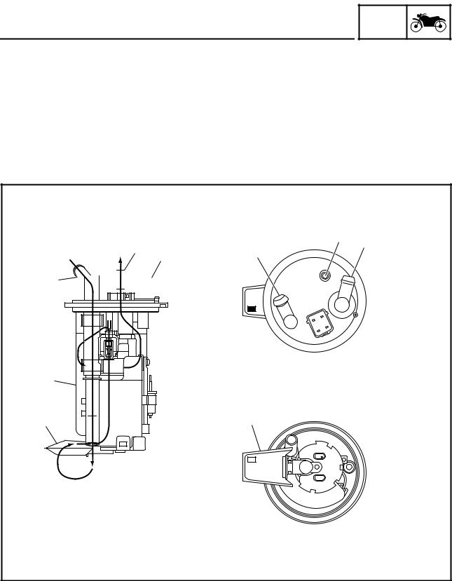
The fuel pump, which is mounted in the fuel tank, draws the fuel directly from the tank and pumps it to the injector.
A filter that is provided in the fuel pump prevents any debris in the fuel tank from entering the fuel system downstream of the pump.
The pump consists of a pump unit, electric motor, filter, and valves.
The pump unit is a Wesco type rotary pump that is connected to the motor shaft.
A relief valve is provided to prevent the fuel pressure from rising abnormally if the fuel hose becomes clogged. This valve opens when the fuel pressure at the discharge outlet reaches between 440 and 640 kpa, and returns the fuel to the fuel tank.
|
É 4 |
|
4 |
5 |
È |
5 |
3 |
|
|
|
|
|
|
3 

 Ê
Ê
2
1 |
1 |
1 Fuel filter |
|
|
|
È From main fuel tank |
|||
2 Fuel inlet strainer |
É To injectors |
||
3 Fuel inlet |
Ê To main fuel tank |
||
4 Fuel outlet |
|
|
|
5 Air vent pipe |
|
|
|
1 - 8
FEATURES
Pressure regulator
GEN INFO
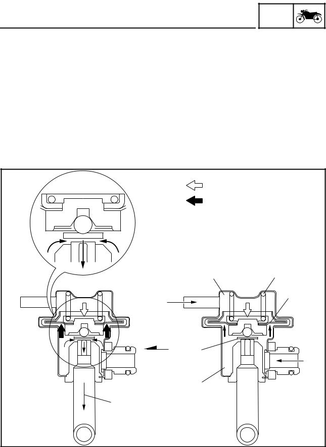
It regulates the fuel pressure that is applied to the injectors that supply fuel to the cylinders in order to maintain a constant pressure.
The fuel that is delivered by the fuel pump fills the fuel chamber through the fuel inlet of the regulator and exerts pressure on the diaphragm in the direction for opening the valve.
A spring that is provided in the spring chamber exerts pressure on the diaphragm in the direction for closing the valve, in contrast to the pressure of the fuel. Thus, the valve cannot open unless the fuel pressure overcomes the spring force.
By the atmospheric pressure applied to the spring chamber and when the fuel pressure exceeds the sum of the atmospheric pressure and spring force, the diaphragm opens the valve, allowing fuel to return to the fuel tank from the return hose.
Therefore, the fuel pressure applied to the injectors by the pressure regulator is controlled by the atmospheric pressure and the spring force to maintain the fuel pressure in accordance to the changes of the atmospheric pressure.
È |
|
É |
|
1 |
2 |
8 |
3 |
|
|
7 |
|
|
4 |
6 |
|
5 |
|
1 Spring chamber |
4 Fuel inlet |
7 Valve |
È Spring pressure |
2 Spring |
5 Fuel outlet |
8 Atmospheric pressure |
É Fuel pressure |
3 Diaphragm |
6 Fuel chamber |
sensor |
|
1 - 9

FEATURES
Fuel injector
GEN INFO
Upon receiving injection signals from the ECU, the fuel injector injects fuel. In the normal state, the core is pressed downward by the force of the spring, as illustrated. The needle that is integrated with the bottom of the core keeps the fuel passage closed.
When the current flows to the coil in accordance with the signal from the ECU, the core is drawn upward, allowing the flange that is integrated with the needle to move to the spacer. Since the distance of the movement of the needle is thus kept constant, the opening area of the fuel passage also becomes constant. Because the pressure difference of the fuel to the intake manifold pressure is kept constant by the pressure regulator, the fuel volume varies in proportion to the length of time the coil is energized. The injector that has been recently adopted has a four-hole type injection orifice that enhances the atomization of fuel and improves combustion efficiency.
1
2
3
7 
 4
4
5
6
1 Fuel |
5 Needle |
2 Coil |
6 Inject |
3 Core |
7 Flange |
4 Spacer |
|
1 - 10
FEATURES
Crankshaft position sensor
GEN INFO
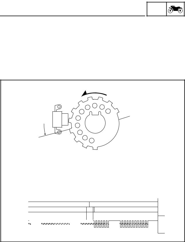
The crankshaft position sensor uses the signals of the crankshaft position sensor that is mounted on the left side of the crankshaft. When the rotation of the pickup rotor that is attached to the crankshaft causes the projections on the rotor to pass by the crankshaft position sensor, an electromotive force is generated in the coil. The voltage of this force is then input into the ECU, which calculates the position of the crankshaft and the speed of the engine. The ignition timing is then determined in accordance with the calculated data, in order to determine the corresponding injection timing. Based on the changes in the time intervals of the signals generated by the crankshaft position sensor, the ECU calculates the ignition timing advance to suit the operating conditions. The injection timing is also advanced in accordance with the ignition timing in order to supply fuel to the engine at an optimal timing.
È
I
10˚ |
T |
I |
|
|
H
É
|
|
2 3 |
|
|
|
|
|
|
|
|
|
|
|
|
|
|
|
|
|
|
|
|
|
|
|
|
|
||||||||
#1 |
|
|
Ë |
|
|
|
|
|
|
|
|
|
|
Ì |
|
|
|
|
|
|
Í |
|
|
|
|
|
|
|
|
||||||
|
|
|
|
|
|
|
|
|
|
|
|
|
|
|
|
|
|
|
|
|
|
|
|
||||||||||||
#2 |
|
|
|
Í |
|
|
|
|
|
Î |
|
|
Ë |
|
|
|
|
|
|||||||||||||||||
|
|
|
|
|
|
|
|
|
|
|
|
|
|
|
|
|
|
|
|
|
|
|
|
|
4 |
|
|
|
|
|
|
||||
Ê |
|
|
|
|
|
|
|
|
|
|
|
|
|
|
|
|
|
|
|
|
|
|
|
|
|
|
|
|
|
|
|
|
|
|
|
|
|
|
|
|
|
|
|
|
|
|
|
|
|
|
|
|
|
|
|
|
|
|
|
|
|
|
|
|
|
|
|
|
|
|
|
|
|
|
|
|
|
|
|
|
|
|
|
|
|
|
|
|
|
|
|
|
|
|
|
|
|
|
|
|
|
|
|
|
|
|
|
1
5PX |
- |
00 |
|
||
|
|
Î |
|
Ë |
|
Ì |
|
Í |
|||
|
Ì |
|
|
Í |
|
|
Î |
|
|
|
|
|
|
|
|
|
|
|
|
5
1 Pickup rotor |
È Direction of rotation |
2 Identification of cylinder #1 (82° BTDC) |
É Compression stroke of cylinder #1 (10° BTDC) |
3 Ignition of cylinder #1 (10° BTDC) |
Ê Crankshaft position sensor |
4 Identification of cylinder #2 |
Ë Compression |
5 Ignition of cylinder #2 |
Ì Combustion |
|
Í Exhaust |
|
Î Intake |
1 - 11
FEATURES
Cylinder identification sensor
GEN INFO
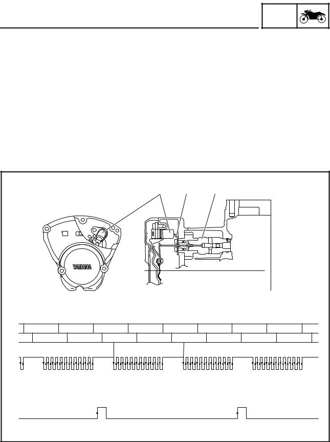
The cylinder identification sensor is installed on the camshaft drive gear cover. When the cam of cylinder #1 rotates, the pickup rotor installed on the cam also rotates. When the pickup rotor passes by the sensor, trigger poles on the rotor generate a signal and send it to the ECU. Based on this signal and the signal from the crankshaft position sensor, the ECU then actuates the injectors to supply fuel.
Cylinder identification
When the crank angle is 110 degrees or higher, no signals are transmitted from the crankshaft position sensor to the ECU. Once the crank angle is less than 110 degrees, the first signal that the ECU receives from the sensor identifies cylinder #1 at 82° BTDC. When the ECU receives a signal from the cylinder identification sensor, cylinder #1 is at 82° BTDC on the exhaust stroke. When the ECU does not receive a signal from the cylinder identification sensor, cylinder #1 is at 82° BTDC on the compression stroke.
|
|
|
|
3 |
2 |
1 |
|
|
#1 |
Ê |
Ë |
Ì |
Í |
Ê |
Ë |
Ì |
Í |
#2 |
Ì |
Í |
Ê |
Ë |
Ì |
Í |
Ê |
Ë |
|
|
|
4 |
|
5 |
|
|
|
È |
|
|
|
|
|
|
|
|
É |
|
|
|
|
|
|
|
|
1 Front cylinder camshaft |
È Crankshaft position sensor signal |
2 Front cylinder camshaft end cover |
É Cylinder identification sensor signal |
3 Cylinder identification sensor |
Ê Compression |
4 Exhaust stroke of cylinder #1 (82° BTDC) |
Ë Combustion |
5 Compression stroke of cylinder #1 (82° BTDC) |
Ì Exhaust |
|
Í Intake |
1 - 12
FEATURES
Throttle position sensor
GEN INFO
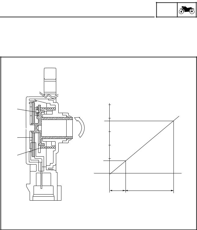
The throttle position sensor measures the intake air volume by detecting the position of the throttle valve. It detects the mechanical angle of the throttle valve through the positional relationship between the moving contact that moves in unison with the throttle shaft and the resistor board. In actual operation, the ECU supplies 5 V power to both ends of the resistor board and the voltage that is output by the throttle position sensor is used to determine the angle of the throttle valve.
|
È |
|
5.0 |
|
|
1 |
|
|
4.0 |
|
|
3.88 |
|
|
3.0 |
|
|
2 |
|
|
2.0 |
|
|
3 |
|
|
1.0 |
|
|
0.68 V |
|
|
|
Ê |
Ë |
É |
17˚ |
97˚ |
1 Moving contact |
È Output voltage |
2 Resistor board |
É Idling output position |
3 Spring |
Ê Full close |
|
Ë Full open |
1 - 13
Loading...