


ST SMP100-8, SMP100LC-35, SMP100-65, SMP100-120, SMP100-140 User Manual
...SMP100-120
SMP100-xxx
COMMUNICATION EQUIPMENT PROTECTION: TRISIL TM
FEATURES
BIDIRECTIONAL CROWBAR PROTECTION VOLTAGE RANGE : FROM 8V to 270V
REPETITIVE PEAK PULSE CURRENT: IPP = 100 A (10/1000 μs)
HOLDING CURRENT: IH = 150mA or 225mA LOW LEAKAGE CURRENT: IR = 2 μA max
DESCRIPTION
The SMP100 series are transient surge arrestors used for the protection of sensitive telecom equipment.
MAIN APPLICATIONS
Any sensitive equipment requiring protection against lightning strikes :
ANALOG AND DIGITAL LINE CARDS MAIN DISTRIBUTION FRAMES TERMINALS AND TRANSMISSION EQUIPMENT
GAS-TUBE REPLACEMENT
BENEFITS
NO AGEING AND NO NOISE
IF DESTROYED, THE SMP100 FALLS INTO SHORTCIRCUIT,STILLENSURINGPROTECTION
BOARD SPACE SAVING
SMB
(JEDEC DO-214AA)
SCHEMATIC DIAGRAM
COMPLIES WITH THE FOLLOWING STANDARDS:
ITU K20
VDE0433
VDE0878
IEC-1000-4-5
FCC Part 68, lightning surge type A
FCC Part 68, lightning surge type B
Peak Surge |
Voltage |
Current |
Admissible |
Necessary |
Voltage |
Waveform |
Waveform |
Ipp |
Resistor |
(V) |
(μs) |
(μs) |
(A) |
(Ω) |
4000 |
10/700 |
5/310 |
100 |
- |
4000 |
10/700 |
5/310 |
100 |
- |
4000 |
1.2/50 |
1/20 |
100 |
- |
level 4 |
10/700 |
5/310 |
100 |
- |
level 4 |
1.2/50 |
8/20 |
100 |
- |
1500 |
10/160 |
10/160 |
200 |
- |
800 |
10/560 |
10/560 |
100 |
- |
100 |
9/720 |
5/320 |
25 |
- |
BELLCORE TR-NWT-001089 |
2500 |
2/10 |
2/10 |
500 |
- |
First level |
1000 |
10/1000 |
10/1000 |
100 |
- |
BELLCORE TR-NWT-001089 |
5000 |
2/10 |
2/10 |
500 |
- |
Second level |
|
|
|
|
|
CNET l31-24 |
4000 |
0.5/700 |
0.8/310 |
100 |
- |
August 1999 - Ed : 8A |
1/9 |
SMP100-xxx
THERMAL RESISTANCES
Symbol |
|
Parameter |
|
Value |
Unit |
Rth(j-I) |
Junction to leads |
|
20 |
°C/W |
|
Rth(j-a) |
Junction to ambient on printed circuit |
|
100 |
°C/W |
|
|
(with standard footprint dimensions) |
|
|
|
|
ABSOLUTE MAXIMUM RATINGS (Tamb = 25°C) |
|
|
|
||
Symbol |
|
Parameter |
|
Value |
Unit |
Ipp |
Peak pulse current: |
|
|
|
|
|
μ |
(open circuit voltage waveform 1 kV |
μ |
100 |
A |
|
10/1000 s |
10/1000 s) |
|||
|
μ |
(open circuit voltage waveform 4 kV, |
μ |
150 |
A |
|
5/310 s |
10/700 s) |
|||
|
8/20 μs |
(open circuit voltage waveform 4 kV |
1.2/50 μs) |
250 |
A |
|
2/10 μs |
(open circuit voltage waveform 2.5kV |
2/10 μs) |
500 |
A |
IFS |
Fail-safe mode |
8/20 μs |
5 |
kA |
|
ITSM |
Non repetitive surge peak on-state current |
50Hz |
55 |
A |
|
|
One cycle |
|
60Hz |
60 |
A |
|
Non repetitive surge peak on-state current |
0.2s |
25 |
A |
|
|
F = 50Hz |
|
2s |
12 |
A |
TL |
Maximum lead temperature for soldering during 10s |
260 |
°C |
||
Tstg |
Storage temperature range |
|
- 55 to + 150 |
°C |
|
Tj |
Maximum junction temperature |
|
150 |
°C |
|
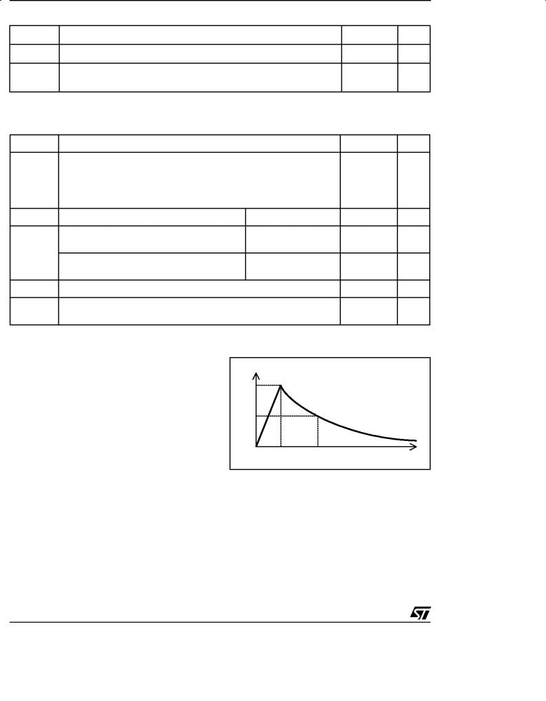
Note 1: Pulse waveform
% IPP
|
μ |
|
μ |
tp = 1000 |
μ |
100 |
|
|
|
10 / 1000 s |
tr = 10 |
s |
s |
|
|
|
|||
8 / 20 μs |
tr = 8 μs |
tp = 20 μs |
|
|
|
|
|||
μ |
tr = 5 |
μ |
s |
μ |
|
|
|
||
5 / 310 |
s |
|
tp = 310 |
s |
50 |
|
|
||
μ |
s |
tr = 1 |
μ |
s |
μ |
|
|
|
|
1 / 20 |
|
tp = 20 s |
|
|
|
|
|||
2 / 10 μs |
tr = 2 μs |
tp = 10 μs |
|
0 |
|
|
|||
|
|
|
|
|
|
|
tp |
t |
|
|
|
|
|
|
|
|
tr |
||
2/9

SMP100-xxx
ELECTRICAL CHARACTERISTICS (Tamb = 25°C) |
|
Symbol |
Parameter |
VRM |
Stand-off voltage |
IRM |
Leakage current at stand-off voltage |
VR |
Continuous reverse voltage |
IR |
Continuous reverse current |
VBR |
Breakdown voltage |
VBO |
Breakover voltage |
IH |
Holding current |
IBO |
Breakover current |
IPP |
Peak pulse current |
C |
Capacitance |
STATIC PARAMETERS |
|
|
|
|
|
|
|
|
Type |
IRM @ VRM |
IR @ VR |
VBO @ IBO |
IH |
C |
|||
|
||||||||
|
max. |
|
max. |
max. |
|
min. |
typ. |
|
|
|
|
|
note 1 |
note 2 |
|
note 3 |
note 4 |
|
μA |
V |
μA |
V |
V |
mA |
mA |
pF |
SMP100-8 |
2 |
6 |
50 |
8 |
20 |
800 |
50(typ) |
100 |
SMP100LC-35 |
2 |
32 |
50 |
35 |
55 |
800 |
150 |
90 |
SMP100-65 |
2 |
55 |
50 |
65 |
80 |
800 |
150 |
160 |
SMP100-120 |
2 |
110 |
50 |
120 |
160 |
800 |
150 |
140 |
SMP100-140 |
2 |
120 |
50 |
140 |
200 |
800 |
150 |
140 |
SMP100-200 |
2 |
170 |
50 |
200 |
265 |
800 |
150 |
130 |
SMP100-230 |
2 |
200 |
50 |
230 |
300 |
800 |
150 |
120 |
SMP100-270 |
2 |
230 |
50 |
270 |
350 |
800 |
150 |
120 |
SMP100-140H225 |
2 |
120 |
50 |
140 |
200 |
800 |
225 |
140 |
SMP100-200H225 |
2 |
170 |
50 |
200 |
265 |
800 |
225 |
130 |
SMP100-230H225 |
2 |
200 |
50 |
230 |
300 |
800 |
225 |
130 |
SMP100-270H225 |
2 |
230 |
50 |
270 |
350 |
800 |
225 |
120 |
Note 1 : IR measured at VR guarantees VBR>VR
Note 2 : Measured at 50Hz, see test circuit 1. In any case VBOmin ≥ VBR
Note 3 : See functional holding current test circuit 2.
Note 4 : VR=1V bias, VRMS=1V, F=1MHz.
3/9
 Loading...