


LM4041AICT-1.2
Table of contents
 Loading...
ST LM4041AICT-1.2, LM4041BICT-1.2, LM4041CICT-1.2, LM4041DICT-1.2, LM4041AILT-1.2 User Manual
...
This is information on a product in full production.
July 2012 Doc ID 018817 Rev 3 1/16
16
LM4041xx
Precision micropower shunt voltage reference
Datasheet − production data
Features
■ Fixed 1.225 V typical output voltage
■ Ultra low operating current: 40 µA at 25 °C
■ High precision: +/- 0.1% @ 25 °C (0.2%, 0.5%
and 1% versions are also available)
■ Stable when used with capacitive loads
■ Industrial (- 40 to+ 85 °C) and Extended (- 40
to +125 °C) temperature range versions
available
■ 100 ppm/°C maximum temperature coefficient
■ Available in SOT23-3L and SOT323-5L
packages
Applications
■ Computers
■ Battery chargers
■ Switch mode power supply
■ Battery operated equipment
■ Data acquisition systems
■ Energy management
■ Instrumentation
Description
The LM4041 is a micropower shunt voltage
reference, providing a stable 1.225 V output
voltage, with an initial accuracy of 0.1% @ 25 °C
and a low temperature coefficient. Available in
SOT323-5L and SOT23-3L surface mount
packages, it can be designed in applications
where space saving is a critical issue. The low
operating current is a key advantage for power
restricted designs. In addition, the LM4041 is very
stable and can be used in a broad range of
application conditions.
SOT23-3L
SOT323-5L
www.st.com

Contents LM4041xx
2/16 Doc ID 018817 Rev 3
Contents
1 Pin configuration . . . . . . . . . . . . . . . . . . . . . . . . . . . . . . . . . . . . . . . . . . . . 3
2 Maximum ratings . . . . . . . . . . . . . . . . . . . . . . . . . . . . . . . . . . . . . . . . . . . . 4
3 Electrical characteristics . . . . . . . . . . . . . . . . . . . . . . . . . . . . . . . . . . . . . 5
4 Typical performance characteristics . . . . . . . . . . . . . . . . . . . . . . . . . . . . 6
5 Package mechanical data . . . . . . . . . . . . . . . . . . . . . . . . . . . . . . . . . . . . . 8
6 Order codes . . . . . . . . . . . . . . . . . . . . . . . . . . . . . . . . . . . . . . . . . . . . . . . 14
7 Revision history . . . . . . . . . . . . . . . . . . . . . . . . . . . . . . . . . . . . . . . . . . . 15
LM4041xx Pin configuration
Doc ID 018817 Rev 3 3/16
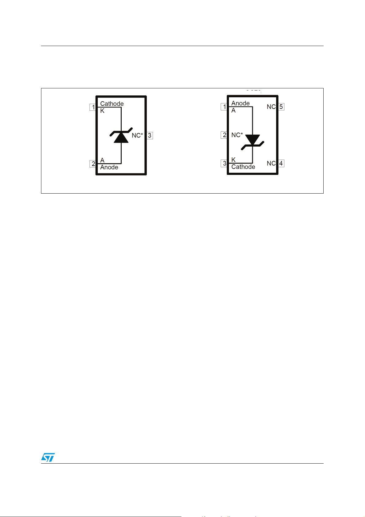
1 Pin configuration
* This pin must be left floating or connected to Anode pin.
Figure 1. Pin connection (top view)
AM09377v1
AM09
378v1
SOT23-3L SOT323-5L
Maximum ratings LM4041xx
4/16 Doc ID 018817 Rev 3
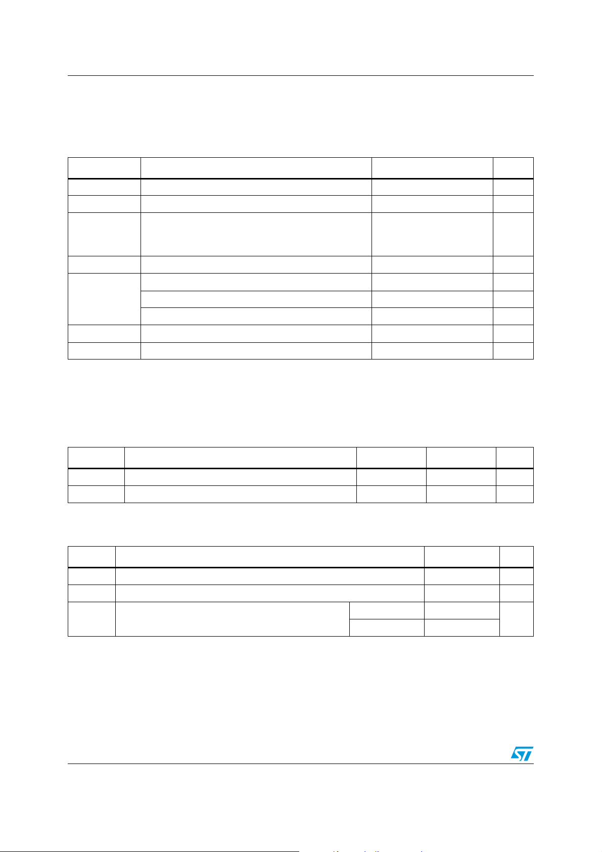
2 Maximum ratings
Note: Absolute maximum ratings are those values beyond which damage to the device may occur.
Functional operation under these conditions is not implied.
Table 1. Absolute maximum ratings
Symbol Parameter Value Unit
I
K
Reverse breakdown current 20 mA
I
F
Forward current 10 mA
P
D
Power dissipation
(1)
SOT23-3L
SOT323-5L
500
536
mW
T
STG
Storage temperature - 65 to +150 °C
ESD
Human Body Model (HBM) 2 kV
Machine Model (MM) 200 V
Charged Device Model 1500 V
T
LEAD
Lead temperature (soldering) 10 sec 260 °C
T
J
Max junction temperature +150 °C
1. P
D
has been calculated with T
AMB
= 25°C and T
JMAX
= 150 °C.
Table 2. Thermal data
Symbol Parameter SOT323-5L SOT23-3L Unit
R
thJA
Thermal resistance junction-ambient 233 248 °C/W
R
thJC
Thermal resistance junction-case 90 136 °C/W
Table 3. Operating conditions
Symbol Parameter Value Unit
I
KMIN
Minimum operating current 40 µA
I
KMAX
Maximum operating current 12 mA
T
OPER
Operating free air temperature range
Industrial - 40 to + 85
°C
Extended - 40 to + 125
LM4041xx Electrical characteristics
Doc ID 018817 Rev 3 5/16
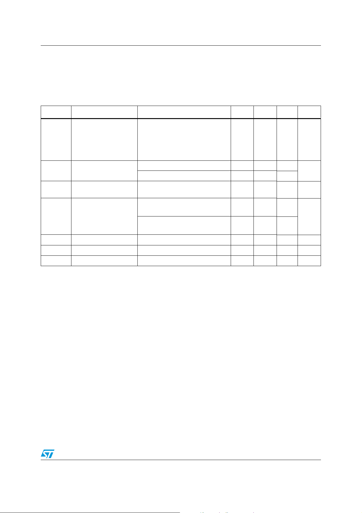
3 Electrical characteristics
T
AMB
= 25 °C, unless otherwise specified.
Note: Limits are 100% production tested at 25 °C. Limits over temperature are guaranteed through
correlation and by design.
Table 4. Electrical characteristics
Symbol Parameter Test conditions Min. Typ. Max. Unit
V
k
Reverse breakdown
voltage
I
k
= 100 µA
LM4041A, 0.1%
LM4041B, 0.2%
LM4041C, 0.5%
LM4041D, 1%
1.2238
1.2225
1.219
1.213
1.225
1.2262
1.2275
1.231
1.237
V
I
kmin
Minimum operating
current
T
amb
= 25 °C 25 40
µA
-40 °C < T
amb
< T
max
(1)
50
ΔV
k
/ΔT
Average temperature
coefficient
(2)
I
k
= 100 µA ± 36 ± 100 ppm/°C
ΔV
k
/ΔI
k
Reverse breakdown
voltage change with
operating current range
I
kmin
< I
k
< 1 mA
- 40 °C < T
amb
< T
max
(1)
0.4
1
1.5
mV
1 mA < I
k
< 12 mA
- 40 °C < T
amb
< T
max
(1)
4
8
10
R
ka
Static impedance ΔI
k
= 100 µA to 1 mA 0.4 1 Ω
K
vh
Long term stability I
k
= 100 µA, t = 1000 hrs 120 ppm
e
n
Wide band noise I
k
= 100 µA, 10 Hz < f < 10 kHz 60 µV
RMS
1. T
max
= 85 °C for LM4041xI (industrial version) and T
max
= 125 °C for LM4041xE (extended version).
2. The average temperature coefficient is defined as: 10
6
x {max(ΔV
k
) / [V
k@25°C
x (T
max
-T
min
)]} [ppm/°C].
Loading...