


 Loading...
AN3411
Application note
IEEE 1588 precision time protocol demonstration for STM32F107 connectivity line microcontroller
1 Introduction
To synchronize Ethernet network devices, an option to use the IEEE1588 (“Precision Time Protocol” - PTP) synchronization protocol is available. Many embedded MCUs and Ethernet PHYs available today in the market are equipped with the PTP HW time stamping unit. The PTP hardware time stamping unit allows very precise time synchronization compared to the SW solution. The hardware solution allows typically sub-microseconds time synchronization precision, the SW solution typically “only” sub-milliseconds range precision. IEEE1588 hardware unit itself is a must for precise synchronization results. In order to meet the IEEE1588 standard requirements, there must be a SW protocol stack running in the microcontroller on top of the HW.
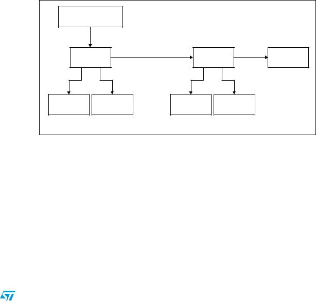
One of the advanced features of the STM32F107's Ethernet MAC controller is the time stamping of the incoming and the outgoing packets by hardware. In this application note, you can find a real application that uses this feature: IEEE1588 PTP HW unit, Figure 1. The objective of this application note is to present a demonstration package built on top of the free lwIP TCP/IP stack and the free PTP stack - PTPd. Support for two hardware platforms is presented, Figure 2.
This software package content is:
●An implementation of IEEE 1588-2002 commonly named PTP v1 over IPv4/UDP using end-to-end delay mechanism.
●An implementation of IEEE 1588-2008 commonly named PTP v2 over IPv4/UDP using both end-to-end and Peer-to-Peer delay mechanisms.
●A target time example, which generates external trigger events at precise time.
Figure 1. STM32F107 PTP HW unit and its interaction with the application software
)%%% CODEAPPLICATION LAYER
4#0 )0 /3 OR3
-!#
(#,+ |
|
0404(7 |
|
|
UNIT |
|
|
|
0(9
.ETWORK
!-
July 2011 |
Doc ID 018905 Rev 1 |
1/37 |
www.st.com

Contents |
AN3411 |
|
|
Contents
1 |
Introduction . . . . . . . . . . . . . . . . . . . . . . . . . . . . . . . . . . . . . . . . . . . . . . . . |
1 |
2 |
Description . . . . . . . . . . . . . . . . . . . . . . . . . . . . . . . . . . . . . . . . . . . . . . . . . |
6 |
3 |
STM32F107 PTP stack implementation software resources . . . . . . . . . |
7 |
|
3.1 Precision time protocol (PTP) . . . . . . . . . . . . . . . . . . . . . . . . . . . . . . . . . . . |
7 |
3.1.1 lwIP stack overview . . . . . . . . . . . . . . . . . . . . . . . . . . . . . . . . . . . . . . . . . 7 3.1.2 PTPd stack overview . . . . . . . . . . . . . . . . . . . . . . . . . . . . . . . . . . . . . . . . 8
4 |
STM32F107 PTP hardware unit set-up . . . . . . . . . . . . . . . . . . . . . . . . . |
. 9 |
|
|
4.1 |
Initialization of the STM32F107 hardware time stamping unit . . . . . . . . . . |
9 |
|
4.2 |
Correction methods for the local clock . . . . . . . . . . . . . . . . . . . . . . . . . . . . |
9 |
|
4.3 |
Data format of the time stamp . . . . . . . . . . . . . . . . . . . . . . . . . . . . . . . . . |
10 |
|
4.4 |
Computing the default values of the time stamp unit registers . . . . . . . . . |
10 |
|
4.5 |
Generating trigger events . . . . . . . . . . . . . . . . . . . . . . . . . . . . . . . . . . . . . |
12 |
5 |
Software porting of the PTPd stack for STM32F107 . . . . . . . . . . . . . . |
14 |
|
|
5.1 |
Modifications of the STM32F107 Ethernet MAC low level driver . . . . . . . |
14 |
|
5.2 |
Modifications of the lwIP stack . . . . . . . . . . . . . . . . . . . . . . . . . . . . . . . . . |
14 |
|
5.3 |
Modifications of the PTPd stack . . . . . . . . . . . . . . . . . . . . . . . . . . . . . . . . |
15 |
|
5.4 |
Periodic PTPd tasks . . . . . . . . . . . . . . . . . . . . . . . . . . . . . . . . . . . . . . . . . |
15 |
|
5.5 |
lwIP configuration . . . . . . . . . . . . . . . . . . . . . . . . . . . . . . . . . . . . . . . . . . . |
15 |
|
5.6 |
PTPd configuration . . . . . . . . . . . . . . . . . . . . . . . . . . . . . . . . . . . . . . . . . . |
15 |
6 |
Getting started with the demonstration software . . . . . . . . . . . . . . . . |
17 |
|
|
6.1 |
Package directories . . . . . . . . . . . . . . . . . . . . . . . . . . . . . . . . . . . . . . . . . |
17 |
|
6.2 |
Configuration of the demonstration boards . . . . . . . . . . . . . . . . . . . . . . . |
17 |
6.2.1 STEVAL-PCC010V1 hardware configuration . . . . . . . . . . . . . . . . . . . . . 18 6.2.2 STM3210C-EVAL hardware configuration . . . . . . . . . . . . . . . . . . . . . . . 20
6.3 Configuration of the PTPd SW project . . . . . . . . . . . . . . . . . . . . . . . . . . . 20
6.3.1 HW platform selection . . . . . . . . . . . . . . . . . . . . . . . . . . . . . . . . . . . . . . 21 6.3.2 MAC and IP address settings . . . . . . . . . . . . . . . . . . . . . . . . . . . . . . . . 22 6.3.3 PTPd settings . . . . . . . . . . . . . . . . . . . . . . . . . . . . . . . . . . . . . . . . . . . . 22
2/37 |
Doc ID 018905 Rev 1 |

AN3411 |
|
|
Contents |
|
|
|
|
|
6.3.4 |
Compiling the project and flashing the HW platform . . . . . . . . . |
. . . . . . 23 |
6.4 |
Application boards connections . . . . . . . . . . . . . . . . . . . . . . . . . . . . |
. . . . 23 |
|
6.4.1 Back-to-back connection of two boards . . . . . . . . . . . . . . . . . . . . . . . . . 24 6.4.2 Boundary clock switch option . . . . . . . . . . . . . . . . . . . . . . . . . . . . . . . . . 24 6.4.3 Linux LiveUSB . . . . . . . . . . . . . . . . . . . . . . . . . . . . . . . . . . . . . . . . . . . . 25
|
6.5 |
How to use the precise time information in the customer application |
. . . 28 |
|
|
|
6.5.1 |
PTPd operation overview . . . . . . . . . . . . . . . . . . . . . . . . . . . . . . . . |
. . . . 28 |
|
|
6.5.2 |
Target time as external trigger example . . . . . . . . . . . . . . . . . . . . . |
. . . . 29 |
|
6.6 |
PTPd project example structure . . . . . . . . . . . . . . . . . . . . . . . . . . . . . |
. . . 30 |
|
|
6.7 |
Precision of the PTPd system . . . . . . . . . . . . . . . . . . . . . . . . . . . . . . |
. . . 30 |
|
7 |
Conclusion . |
. . . . . . . . . . . . . . . . . . . . . . . . . . . . . . . . . . . . . . . . . . . . |
. . . 34 |
|
8 |
References . . |
. . . . . . . . . . . . . . . . . . . . . . . . . . . . . . . . . . . . . . . . . . . . |
. . 35 |
|
9 |
Revision history . . . . . . . . . . . . . . . . . . . . . . . . . . . . . . . . . . . . . . . . . |
. . 36 |
||
Doc ID 018905 Rev 1 |
3/37 |

List of tables |
AN3411 |
|
|
List of tables
Table 1. Examples of different default addend register values vs. increment register value
for SysClk = 72 MHz . . . . . . . . . . . . . . . . . . . . . . . . . . . . . . . . . . . . . . . . . . . . . . . . . . . . . . 11 Table 2. STEVAL-PCC010V1 MII/RMII interface STM32F107 add-on board selection
by solder bridges SB1, SB2 and SB3 . . . . . . . . . . . . . . . . . . . . . . . . . . . . . . . . . . . . . . . . . 19 Table 3. PTPd STM32F107 test set-up . . . . . . . . . . . . . . . . . . . . . . . . . . . . . . . . . . . . . . . . . . . . . . 31 Table 4. Document revision history . . . . . . . . . . . . . . . . . . . . . . . . . . . . . . . . . . . . . . . . . . . . . . . . . 36
4/37 |
Doc ID 018905 Rev 1 |

AN3411 |
List of figures |
|
|
List of figures
Figure 1. |
STM32F107 PTP HW unit and its interaction with the application software . . . . . . . . . . . . |
. 1 |
Figure 2. |
Supported evaluation boards (STM3210C-EVAL and STEVAL-PCC010V1). . . . . . . . . . . |
. 6 |
Figure 3. |
Simple master - slave clock hierarchy (M - master clock, S - slave clock) . . . . . . . . . . . . . |
. 7 |
Figure 4. |
PTP time stamp data format . . . . . . . . . . . . . . . . . . . . . . . . . . . . . . . . . . . . . . . . . . . . . . . . |
10 |
Figure 5. |
Fine correction method . . . . . . . . . . . . . . . . . . . . . . . . . . . . . . . . . . . . . . . . . . . . . . . . . . . . |
12 |
Figure 6. |
PTPd software package directory structure . . . . . . . . . . . . . . . . . . . . . . . . . . . . . . . . . . . . |
17 |
Figure 7. |
STEVAL-PCC010V1 - ST802RT1 board configuration . . . . . . . . . . . . . . . . . . . . . . . . . . . |
18 |
Figure 8. |
STEVAL-PCC010V1 - STM32F107 demonstration board set-up . . . . . . . . . . . . . . . . . . . . |
19 |
Figure 9. |
STM3210C-EVAL configuration for MII functionality in PTPd application example . . . . . . |
20 |
Figure 10. |
Change the project compilation defines according to the board used (RIDE7) . . . . . . . . . |
21 |
Figure 11. |
Both addresses, MAC and IP, are derived from constant CLIENT_ADDR |
|
|
(/src/netconf.c) . . . . . . . . . . . . . . . . . . . . . . . . . . . . . . . . . . . . . . . . . . . . . . . . . . . . . . . . . . |
22 |
Figure 12. |
PTPd settings . . . . . . . . . . . . . . . . . . . . . . . . . . . . . . . . . . . . . . . . . . . . . . . . . . . . . . . . . . . |
23 |
Figure 13. |
Back-to-back connection of the two boards . . . . . . . . . . . . . . . . . . . . . . . . . . . . . . . . . . . . |
24 |
Figure 14. |
Two boards connection through boundary clock switch, packet sniffing in PC. . . . . . . . . . |
25 |
Figure 15. |
STM3210C-EVAL connected to a PC running Linux LiveUSB distribution |
|
|
with software PTPd daemon . . . . . . . . . . . . . . . . . . . . . . . . . . . . . . . . . . . . . . . . . . . . . . . . |
26 |
Figure 16. |
PTPd running in the Linux console window . . . . . . . . . . . . . . . . . . . . . . . . . . . . . . . . . . . . |
26 |
Figure 17. |
Wireshark - PTP packet analysis . . . . . . . . . . . . . . . . . . . . . . . . . . . . . . . . . . . . . . . . . . . . |
27 |
Figure 18. |
PTPd operation overview . . . . . . . . . . . . . . . . . . . . . . . . . . . . . . . . . . . . . . . . . . . . . . . . . . |
29 |
Figure 19. |
PTPd project example structure . . . . . . . . . . . . . . . . . . . . . . . . . . . . . . . . . . . . . . . . . . . . . |
30 |
Figure 20. |
PTPd STM32F107 test set-up . . . . . . . . . . . . . . . . . . . . . . . . . . . . . . . . . . . . . . . . . . . . . . |
31 |
Figure 21. |
Precision reached using the default crystal and built in oscillator, the synchronization |
|
|
interval has been set to 1 second . . . . . . . . . . . . . . . . . . . . . . . . . . . . . . . . . . . . . . . . . . . . |
32 |
Figure 22. |
Precision reached using the external oscillator on the STM3210C-EVAL, |
|
|
the synchronization interval has been set to 1 second . . . . . . . . . . . . . . . . . . . . . . . . . . . . |
32 |
Figure 23. |
Precision reached using the default crystal and built in oscillator, the synchronization |
|
|
interval has been set to 0.125 second . . . . . . . . . . . . . . . . . . . . . . . . . . . . . . . . . . . . . . . . |
33 |
Figure 24. |
Precision reached using the external oscillator on the STM3210C-EVAL, |
|
|
the synchronization interval has been set to 0.125 second . . . . . . . . . . . . . . . . . . . . . . . . |
33 |
Doc ID 018905 Rev 1 |
5/37 |

Description |
AN3411 |
|
|
2 Description
This application note presents implementation of the IEEE1588-2008 PTP protocol for STM32F107 microcontroller. IEEE1588 – 2008 is not backward compatible to the older IEEE1588 - 2002 version of this specification. IEEE1588-2002 implementation example is also available in source codes for STM32F107, but it is not described in this application note. Industrializations focus of the customers today is IEEE1588-2008.
The PTP daemon (PTPd) implements the precision time protocol (PTP) as defined in the IEEE1588 specification. The PTPd Version 1 implements IEEE 1588-2002 compliant functionality, and the PTPd Version 2 implements newer IEEE 1588-2008 specification. PTPd was developed to provide a precise time coordination of LAN connected computers. PTPd can run on most 32-bit and 64-bit processors. It does not require any FPU, therefore it is by definition easy to be used in small embedded processors. The PTPd originally runs on Linux, μClinux™, FreeBSD®, and NetBSD operating systems. It is also easy to port it to other platforms. The PTPd time stamping unit is originally software based and therefore for the STM32 use it has been adapted in order to benefit from the STM32 PTP hardware unit.
Figure 2. Supported evaluation boards (STM3210C-EVAL and STEVAL-PCC010V1)
The SW implementation of PTPd is based on STMicroelectronics™ application note AN3102 (lwIP TCP/IP stack demonstration for STM32F107xx connectivity line microcontrollers) as available from ST website www.st.com/stm32. The AN3102 source codes of the project have been modified for operation with the PTPd protocol stack.
6/37 |
Doc ID 018905 Rev 1 |
AN3411 |
STM32F107 PTP stack implementation software resources |
|
|
3STM32F107 PTP stack implementation software resources
3.1Precision time protocol (PTP)
The IEEE 1588 standard defines a protocol that allows precise clock synchronization in measurement and control systems implemented with technologies such as network communication, local computing and distributed objects. The protocol applies to systems that communicate by local area networks supporting multicast messaging, including Ethernet. This protocol is used to synchronize systems that include clocks of different precision, resolution and stability. The protocol supports system-wide synchronization accuracy in the sub-microsecond range with a minimum network and local clock computing resources. The message-based protocol, known as the precision time protocol (PTP), is transported over UDP/IP. The system or network (example in Figure 3) is classified into master and slave nodes for distributing the timing/clock information.
Figure 3. Simple master - slave clock hierarchy (M - master clock, S - slave clock)
'RANDNMASTER |
|
|
|
|
|
|
|
|
/RDINARYYCLOCKK |
|
|
|
|
|
|
|
|
|
- |
|
|
|
|
|
|
|
|
3 |
|
|
|
|
|
|
|
"OUNDARY |
- |
3 |
"OUNDARY |
- |
3 |
/RDINARY |
||
|
CLOCKK |
|
|
|
CLOCKK |
|
|
CLOCKK |
- |
- |
|
|
- |
- |
|
|
|
3 |
3 |
|
|
3 |
3 |
|
|
|
/RDINARY |
/RDINARY |
/RDINARY |
/RDINARY |
|
|
|||
CLOCKK |
CLOCKK |
CLOCKK |
CLOCKK |
|
|
|||
|
|
|
|
|
|
|
|
!- |
The precision time protocol uses multicast messaging over UDP/IP. The underlying TCP/IP stack should have multicast support functionality or at least has to pass multicast messages. There are at least two free implementations of the TCP/IP stacks - lwIP (Light weight IP) and μIP. The lwIP TCP/IP stack has been chosen for the PTPd demonstration because of its support for multicast and IGMP messages. The μIP TCP/IP stack can also work, but it does not have support for IGMP protocol so it is not suitable for networks where switches with IGMP snooping are used. The IEEE1588 protocol itself has at least one free implementation with many derivates. Its name is PTPd and it is designed for Linux and FreeBSD systems.
3.1.1lwIP stack overview
The lwIP TCP/IP stack is a free TCP/IP stack developed by Adam Dunkels at the Swedish Institute of Computer Science (SICS) and is licensed under the BSD license. The source code can be downloaded from http://savannah.nongnu.org/projects/lwip/. The lwIP TCP/IP stack supports the following protocols: IPv4, IPv6, UDP, TCP, ICMP, IGMP, SNMP, ARP and PPP.
Doc ID 018905 Rev 1 |
7/37 |

STM32F107 PTP stack implementation software resources |
AN3411 |
|
|
The lwIP offers three types of API (“Application Programming Interface”):
●A raw API: it is the native API used by the lwIP stack itself to interface with the different protocols.
●A NETCONN API: it is a sequential API with a higher level of abstraction than the raw API.
●A socket API: it is a Berkeley-like API
The API used to build the PTPd demonstration with STM32F107 is the raw API. The raw API selection has been made because of the standalone implementation of the lwIP TCP/IP stack example. Nevertheless the achievable time synchronization precision should be the same for all three APIs, but neither Netconn nor socket API has been used and changed to reflect the needs of timestamps in this PTPd implementation example. Only the raw API has been modified to work with the PTPd software stack. Both, the Netconn and the Socket APIs need an operating system. More information about the lwIP protocol version for the STM32F107 microcontroller can be found in the application note AN3102 available from the STMicroelectronics website http://www.st.com/stm32.
3.1.2PTPd stack overview
The PTP daemon (PTPd) is a free implementation of the precision time protocol (PTP) as defined by the IEEE 1588 (2002/2008) standards. PTPd is complete implementation of the IEEE 1588 specification for standard (non-boundary) clock. The source code for PTPd is freely available under a BSD-style license. The source code can be downloaded from www.ptpd.sourceforge.net. The PTPd has two versions. PTP Version 1 implements IEEE 1588-2002 specification, and PTP Version 2 implements IEEE 1588-2008 specification. As mentioned, the PTPd protocol has to be adapted to work with the PTP HW time stamping unit of the STM32F107 microcontroller.
8/37 |
Doc ID 018905 Rev 1 |

AN3411 |
STM32F107 PTP hardware unit set-up |
|
|
4 STM32F107 PTP hardware unit set-up
This chapter describes in details the STM32F107 PTP hardware unit initial set-up, programming steps for the fine correction method and resources for the PTP information triggering in the customer application.
4.1Initialization of the STM32F107 hardware time stamping unit
The first step is the initialization of the time stamping unit of the embedded Ethernet MAC interface of STM32F107. The startup sequence is prepared in ETH_PTPStart function. This enables the time stamping ability of MAC controller, then it set ups default values of the time stamping registers, namely the addend and the increment registers. Finally it sets the current time to 0 s.
1.Mask the time stamp trigger interrupt by setting bit 9 in the MACIMR register.
2.Program time stamp register bit 0 to enable time stamping.
3.Program the sub-second increment register based on the PTP clock frequency.
4.Program the time stamp addend register and set time stamp control register bit 5 (addend register update).
5.Poll the time stamp control register until bit 5 is cleared.
6.To select the fine correction method program time stamp control register bit 1.
7.Program the time stamp high update and time stamp low update registers with the appropriate time value. (can be zero)
8.Set time stamp control register bit 2 (time stamp init).
9.The time stamp counter starts operation as soon as it is initialized with the value written in the time stamp update register.
10.Enable the MAC receiver and transmitter for proper time stamping.
4.2Correction methods for the local clock
There are two possible methods of the clock correction supported in the STM32F107 IEEE1588 time stamping unit: fine and coarse correction methods. In the here described implementation example the fine correction method is used because it allows more precise synchronization results in comparison with the coarse correction method. The correction method should be selected in the initialization step of the hardware time stamping in function ETH_PTPStart. After that only the appropriate functions should be used for the clock correction.
If coarse method is used, only the ETH_PTPTime_UpdateOffset function can be used to perform local time corrections. In contrast if the fine correction method is used, only the ETH_PTPTime_SetTime and ETH_PTPTime_AdjFreq can be used.
ETH_PTPTime_UpdateOffset updates the current clock by the relative difference. The function call argument is added to or subtracted from the current time.
ETH_PTPTime_SetTime sets the absolute time. The function call argument is set as the current time.
ETH_PTPTime_AdjFreq adjusts the addend register value. The argument is the relative change of the default clock frequency in ppb (parts per 109 - billion). If the crystal used in
Doc ID 018905 Rev 1 |
9/37 |

STM32F107 PTP hardware unit set-up |
AN3411 |
|
|
final application is for example 5 ppm off, then setting this value to the 5000 will compensate the error.
Following steps are used to perform the update of the addend register in function AdjFreq:
1.Calculate addend register value.
2.Update the time stamp addend register “ETH_PTPTSAR” with calculated value.
3.Enable the time stamp addend register by setting bit TSARU in ETH_PTPTSCR.
4.3Data format of the time stamp
The registers holding the time stamps are using specific 64-bit format. The highest 32-bit register is unsigned integer holding number of seconds. Lowest 31 bits in the second 32-bit register are used for the fractional part of second and the 32nd bit is a negative sign.
Figure 4. |
|
PTP time stamp data format |
|
|
|
|
|
|
|
|
|
|
|
|||
|
|
|
|
|
|
|
|
|
|
|
|
|
|
|
|
|
|
|
|
|
|
3ECONDS |
|
|
|
|
|
|
|
|
|
|
|
|
|
|
|
|
|
|
|
|
|
|
|
|
|
|
|
|
|
|
|
|
|
|
|
|
|
|
|
|
|
|
|
|
|
|
|
|
|
|
|
|
|
|
|
|
|
|
|
|
|
|
|
S |
|
|
|
3UBSECONDS |
|
|
|
|
|
|
|
|
|
|
|
|
|
|
|
|
|
|
|
|
|
|
|
|
|
|
|
|
|
|
|
|
|
|
|
|
|
|
|
|
|
|
!- |
||
|
|
|
|
|
|
|
|
|
|
|
|
|
|
|
|
|
In order to use the registers value in PTP stack it is necessary to convert these values to another format. Structure with signed, both seconds and nanoseconds, is used. So it is also necessary to convert the subseconds to nanoseconds and vice versa. For this purpose functions ETH_PTPSubSecond2NanoSecond and ETH_PTPNanoSecond2SubSecond are implemented.
This 64-bit data format is used in all time stamp related registers (ETH_PTPTSHR, ETH_PTPTSLR), time stamp update registers (ETH_PTPTSHUR, ETH_PTPTSLUR), Target time registers (ETH_PTPTTHR, ETH_PTPTTLR) and also in the DMA descriptors.
4.4Computing the default values of the time stamp unit registers
If using the Fine correction method, the default values of the addend and the increment registers can be computed as follow.
Equation 1
tick |
= |
Increment |
|
|
109 |
-------------------2----31-------- |
--- |
--- |
-------- |
||
|
|
|
|
|
|
Adden(d Increment) |
|
= |
263 |
||
|
SysClk------------------- |
||||
|
|
|
|
|
|
For example, if SysClk is 72 MHz, we can chose tick approximately 20 ns.
10/37 |
Doc ID 018905 Rev 1 |
AN3411 |
|
|
|
STM32F107 PTP hardware unit set-up |
|
|
|
|
|
Equation 2 |
|
|
|
|
Increment = |
20 |
231 |
|
42.94 43(0x2B) |
---------------------- = |
||||
|
109 |
|
|
|
tick = |
43 |
109 |
= |
20.023ns |
-------- |
||||
|
|
231 |
|
|
We can see that tick is not precisely 20 ns as we choose because of rounding increment value. Using the next equation, we can compute default value of the addend register.
Equation 3
Addend |
= |
263 |
---------------------------------------------- |
||
|
SysClk Increment |
|
Addend = |
263 |
= 2979125334.90 |
---------------- |
||
72M |
43 |
|
Addenddefault = 2979125335(0xb191d857)
Value of the tick can be selected differently but it is necessary to validate the range of the increment and addend registers. The increment register is of data type unsigned char (8-bit) and the addend register is of data type unsigned long (32-bit). It is also necessary to validate the regulation range of the addend register.
Table 1. |
Examples of different default addend register values vs. increment |
||
|
register value for SysClk = 72 MHz |
|
|
|
|
|
|
|
Tick |
Increment |
Addend |
|
|
|
|
|
119 ns |
255 |
0x1DF170C7 |
|
|
|
|
|
100 ns |
215 |
0x238391AA |
|
|
|
|
|
50 ns |
107 |
0x475C1B20 |
|
|
|
|
|
20 ns |
43 |
0xB191D856 |
|
|
|
|
|
14 ns |
30 |
0xFE843E9E |
|
|
|
|
Doc ID 018905 Rev 1 |
11/37 |

STM32F107 PTP hardware unit set-up |
|
|
AN3411 |
|||
|
|
|
|
|
|
|
|
Figure 5. Fine correction method |
|
|
|
||
|
|
|
|
|
||
|
!DDEND REGISTER |
|
|
|
||
|
|
|
|
|
|
|
|
|
|
|
|
|
|
|
|
|
|
|||
|
|
|
|
|||
|
|
|
|
|
||
|
!CCUMULATORTREGISTER |
|
||||
|
|
|
|
|||
|
|
|
|
|
||
|
)NCREMENT TRIGGERG |
X " |
||||
3UBSECOND REGISTER
)NCREMENT TRIGGERG
3ECOND REGISTER
!-
4.5Generating trigger events
In the example delivered with this application note we have used an easy way to generate external trigger events. To enable this feature timer TIM2 should be properly configured following these steps.
1.Remap ITR1 input of TIM2 to the output of target time event by resetting bit TIM2ITR1_IREMAP of register AFIO_MAPR.
2.Set the prescaler, period and counter mode of TIM2.
3.Configure appropriate timer output to PWM1 mode.
4.Enable fast output compare state.
5.Select one pulse mode of TIM2.
6.Select ITR1 as input trigger for TIM2.
7.Select slave mode for TIM2.
If the timer TIM2 is configured to generate the target time events, interrupts can be enabled by unmasking interrupt bit TSTIM in register ETH_MACIMR.
12/37 |
Doc ID 018905 Rev 1 |
Loading...