


 Loading...
MDX-CA680/CA680X
SERVICE MANUAL
US Model
MDX-CA680X
Ver 1.1 2001.05
AEP Model
UK Model
MDX-CA680/CA680X
Photo: MDX-CA680X (US model)
U.S. and foreign patents licensed from Dolby laboratories |
Model Name Using Similar Mechanism |
NEW |
|
Licensing Corporation. |
|||
|
|
||
Base Mechanism Type |
MG-164MA-138 |
||
|
|||
|
|
|
|
|
Optical Pick-up Name |
KMS-241C |
|
|
|
|
SPECIFICATIONS
AUDIO POWER SPECIFICATIONS (US model)
POWER OUTPUT AND TOTAL HARMONIC DISTORTION
23 watts per channel minimum continuous average power into 4 ohms, 4 channels driven from 20 Hz to 20 kHz with no more than 5% total harmonic distortion.
MD Player section
Signal-to-noise ratio |
90 dB |
Frequency response |
10 – 20,000 Hz |
Wow and flutter |
Below measurable limit |
Laser Diode Properties (US model) |
|
Material |
GaAlAs |
Wavelength |
780 nm |
Emission Duration |
Continuous |
Laser output power |
Less than 44.6 µ W* |
*This output is the value measured at a distance of 200 mm from the objective lens surface on the Optical Pick-up Block.
Tuner section
FM
Tuning range |
|
US model: |
87.5 – 107.9 MHz |
AEP, UK models: |
87.5 – 108.0 MHz |
Antenna terminal |
External antenna connector |
Intermediate frequency |
10.7 MHz/450 kHz |
Usable sensitivity |
8 dBf |
Selectivity |
75 dB at 400 kHz |
Signal-to-noise ratio |
66 dB (stereo), |
|
72 dB (mono) |
Harmonic distortion at 1 kHz |
|
|
0.6 % (stereo), |
|
0.3 % (mono) |
Separation |
35 dB at 1 kHz |
Frequency response |
30 – 15,000 Hz |
AM (US model) |
|
Tuning range |
530 – 1,710 kHz |
Antenna terminal |
External antenna connector |
Intermediate frequency |
10.7 MHz/450 kHz |
Sensitivity |
30 µ V |
9-870-242-12 Sony Corporation
MW/LW (AEP, UK models)
Tuning range |
MW: 531 – 1,602 kHz |
|
LW: 153 – 279 kHz |
Aerial terminal |
External aerial connector |
Intermediate frequency |
10.7 MHz/450 kHz |
Sensitivity |
MW: 30 µ V |
|
LW: 40 µ V |
Power amplifier section
Outputs |
Speaker outputs |
|
(sure seal connectors) |
Speaker impedance |
4 – 8 ohms |
Maximum power output |
50 W × 4 (at 4 ohms) |
General
Outputs |
Audio outputs (front/rear) |
|
Power antenna relay control |
|
lead |
|
Power amplifier control lead |
Inputs |
Telephone ATT control lead |
|
BUS control input |
|
connector |
|
BUS audio input connector |
|
Remote controller input |
|
connector |
Tone controls |
Antenna input connector |
US model: |
Bass ± 10 dB at 100 Hz |
||
|
Treble ± 10 dB at 15 kHz |
||
AEP, UK models: |
Bass ± 9 dB at 100 Hz |
||
|
Treble ± 9 dB at 10 kHz |
||
Power requirements |
12 V DC car battery |
||
|
(negative ground) |
|
|
Dimensions |
Approx. 178 × |
50 × |
177 mm |
|
(7 1/8 × 2 × 7 in.) |
|
|
|
(w/h/d) |
|
|
Mounting dimensions |
Approx. 182 × |
53 × |
161 mm |
|
(7 1/4 × 2 1/8 × |
6 3/8 in.) |
|
|
(w/h/d) |
|
|
Mass |
Approx. 1.2 kg |
|
|
|
(2 lb 10 oz) |
|
|
Supplied accessories |
Parts for installation and |
||
|
connections (1 set) |
|
|
|
Front panel case (1) |
||
Note
This unit cannot be connected to a digital preamplifier or an equalizer.
Design and specifications are subject to change without notice.
FM/AM (MW/LW) MINIDISC PLAYER
2001E0500-1 |
e Vehicle Company |
C 2001.5 |
Shinagawa Tec Service Manual Production Group |

MDX-CA680/CA680X
TABLE OF CONTENTS |
|
1. GENERAL |
|
Location of Controls ....................................................... |
3 |
Setting the Clock ............................................................. |
4 |
2.DISASSEMBLY
2-1. |
Disassembly Flow ........................................................... |
10 |
2-2. |
Sub Panel Assy ................................................................ |
10 |
2-3. |
Mechanism Deck (MG-164MA-138) ............................. |
11 |
2-4. |
MAIN Board ................................................................... |
11 |
2-5. |
Heat Sink ......................................................................... |
12 |
2-6. |
SERVO Board ................................................................. |
12 |
2-7. |
MD Cover Assy ............................................................... |
13 |
2-8. |
Float Block ...................................................................... |
13 |
2-9. Lo Motor Assy (Loading) (M903) .................................. |
14 |
|
2-10. Lever (LE23) Assy .......................................................... |
14 |
|
2-11. Holder Assy ..................................................................... |
15 |
|
2-12. Chucking Arm Assy ........................................................ |
15 |
|
2-13. |
Optical Pick-up (KMS-241C) ......................................... |
16 |
2-14. SL Motor Assy (Sled) (M902), |
|
|
|
SP Motor Assy (Spindle) (M901) ................................... |
16 |
3.ELECTRICAL ADJUSTMENTS
|
Test Mode ........................................................................ |
17 |
|
MD Section ..................................................................... |
17 |
|
Tuner Section .................................................................. |
17 |
4. |
DIAGRAMS ................................................................. |
18 |
4-1. |
Block Diagram – SERVO Section – ............................... |
23 |
4-2. |
Block Diagram – TUNER Section – .............................. |
24 |
4-3. |
Block Diagram – MAIN Section – ................................. |
25 |
4-4. Block Diagram – BUS CONTROL/ |
|
|
|
POWER SUPPLY Section – ........................................... |
26 |
4-5. Note for Printed Wiring Boards and |
|
|
|
Schematic Diagrams ....................................................... |
27 |
4-6. Printed Wiring Boards – SERVO Section – ................... |
29 |
|
4-7. Schematic Diagram – SERVO Section (1/2) – ............... |
30 |
|
4-8. Schematic Diagram – SERVO Section (2/2) – ............... |
31 |
|
4-9. Printed Wiring Board – MAIN Board – ......................... |
32 |
|
4-10. |
Schematic Diagram – MAIN Board (1/3) – ................... |
33 |
4-11. |
Schematic Diagram – MAIN Board (2/3) – ................... |
34 |
4-12. |
Schematic Diagram – MAIN Board (3/3) – ................... |
35 |
4-13. |
Printed Wiring Board – SUB Board – ............................ |
36 |
4-14. |
Schematic Diagram – SUB Board – ............................... |
37 |
4-15. |
Printed Wiring Board – KEY Board – ............................ |
38 |
4-16. |
Schematic Diagram – KEY Board – .............................. |
39 |
4-17. IC Pin Function Description ........................................... |
41 |
|
5.EXPLODED VIEWS
5-1. |
General Section ............................................................... |
49 |
5-2. |
Front Panel Section ......................................................... |
50 |
5-3. Mechanism Deck Section-1 (MG-164MA-138) ............ |
51 |
|
5-4. |
Mechanism Deck Section-2 (MG-164MA-138) ............ |
52 |
6. |
ELECTRICAL PARTS LIST ............................... |
53 |
NOTES ON HANDLING THE OPTICAL PICK-UP BLOCK OR BASE UNIT
The laser diode in the optical pick-up block may suffer electrostatic break-down because of the potential difference generated by the charged electrostatic load, etc. on clothing and the human body.
During repair, pay attention to electrostatic break-down and also use the procedure in the printed matter which is included in the repair parts.
The flexible board is easily damaged and should be handled with care.
NOTES ON LASER DIODE EMISSION CHECK
Never look into the laser diode emission from right avove when checking it for adustment. It is feared that you will lose your sight.
NOTES ON HANDLING THE OPTICAL PICK-UP BLOCK (KMS-241C).
The laser diode in the optical pick-up block may suffer electrostatic break-down easily. When handling it, perform soldering bridge to the laser-tap on the flexible board. Also perform measures against electrostatic break-down sufficiently before the operation. The flexible board is easily damaged and should be handled with care.
laser-tap
OPTICAL PICK-UP FLEXIBLE BOARD
Notes on chip component replacement
•Never reuse a disconnected chip component.
•Notice that the minus side of a tantalum capacitor may be damaged by heat.
Flexible Circuit Board Repairing
•Keep the temperature of the soldering iron around 270 ˚C during repairing.
•Do not touch the soldering iron on the same conductor of the circuit board (within 3 times).
•Be careful not to apply force on the conductor when soldering or unsoldering.
CAUTION
Use of controls or adjustments or performance of procedures other than those specified herein may result in hazardous radiation exposure.
SAFETY-RELATED COMPONENT WARNING!!
COMPONENTS IDENTIFIED BY MARK 0 OR DOTTED LINE WITH MARK 0 ON THE SCHEMATIC DIAGRAMS
AND IN THE PARTS LIST ARE CRITICAL TO SAFE OPERATION. REPLACE THESE COMPONENTS WITH SONY PARTS WHOSE PART NUMBERS APPEAR AS SHOWN IN THIS MANUAL OR IN SUPPLEMENTS PUBLISHED BY SONY.
2
SECTION 1 |
MDX-CA680/CA680X |
This section is extracted from |
|
GENERAL |
instruction manual. |
|
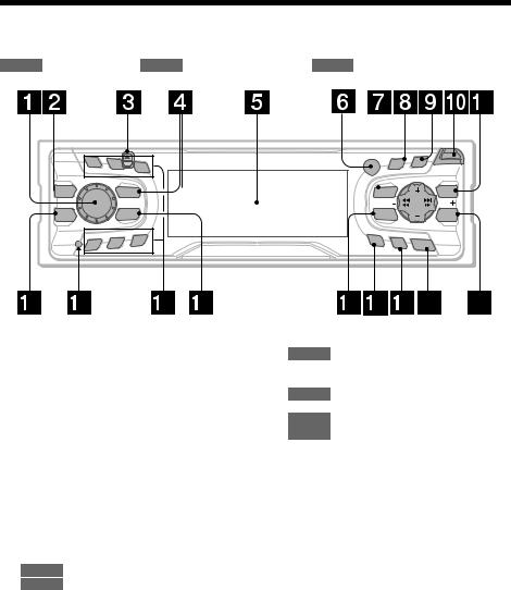
Location of controls
Refer to the pages listed for details.
CD/MD : During Playback RADIO : During radio reception MENU : During menu mode
1
 MBP
MBP
D–BASS
4
2 |
3 |
|
REP |
|
SOURCE |
|
MODE |
|
SHUF |
5 |
6 |
|
PTY |
|
S |
|
|
|
D |
|
|
OPEN |
||
DISPLAY |
SCROLL |
|
|||
|
R |
|
|
|
|
|
|
|
|
|
|
|
/P E |
|
|
||
|
ISC |
|
SE |
|
|
|
D |
|
|
T |
|
MENU |
|
|
|
|
LIST |
SEEK |
|
|
|
|
SEEK |
SOUND |
|
|
|
|
ENTER |
AF |
TA |
OFF |
|
||
|
|
(AEP, UK models)
a Volume control dial 16 b MBP button 22
cZ (eject) button (located on the front side of the unit, behind the front panel) 9
dSOURCE (Power on/Radio/CD/MD) button 8, 9, 11, 13, 14, 16
eDisplay window
fReceptor for the card remote commander
gMENU button 8, 10, 11, 12, 13, 17, 18, 21
hDISPLAY/PTY*1 (display mode change/ programme type) button 9, 11, 15, 18
iSCROLL button 9
jOPEN button 7, 9
kLIST button
CD/MD 11
RADIO 14
lD-BASS button 22
mRESET button (located on the front side of the unit, behind the front panel) 7
nNumber buttons
CD/MD
(3) REP 10
(6) SHUF 10
RADIO 13, 14, 16, 17
oMODE button
CD/MD 9, 11
RADIO 13, 14, 16
pSOUND button 20, 22
qAF button*1 15, 17
rTA button *1 16, 17
sOFF (Stop/Power off) button*2 7, 9
tENTER button
CD/MD |
11 |
RADIO |
14, 18 |
MENU |
8, 10, 11, 12, 13, 17, 18, 21 |
*1 AEP, UK models only
*2 Warning when installing in a car without an ACC (accessory) position on the
ignition switch
After turning off the ignition, be sure to press (OFF) on the unit for 2 seconds to turn off the clock display.
Otherwise, the clock display does not turn off and this causes battery drain.
3
MDX-CA680/CA680X
PTY |
|
|
S |
|
|
|
D |
|
|
OPEN |
|||
DISPLAY |
SCROLL |
|||||
|
R |
|
|
|
||
|
|
|
|
|
|
|
|
|
/P E |
|
|
||
|
|
ISC |
|
SE |
|
|
|
D |
|
|
T |
|
|
MENU |
|
|
|
|
|
LIST |
SEEK |
|
|
|
|
|
SEEK |
SOUND |
|
|
|
|
|
ENTER |
AF |
TA |
|
OFF |
|
||
|
|
|
||||
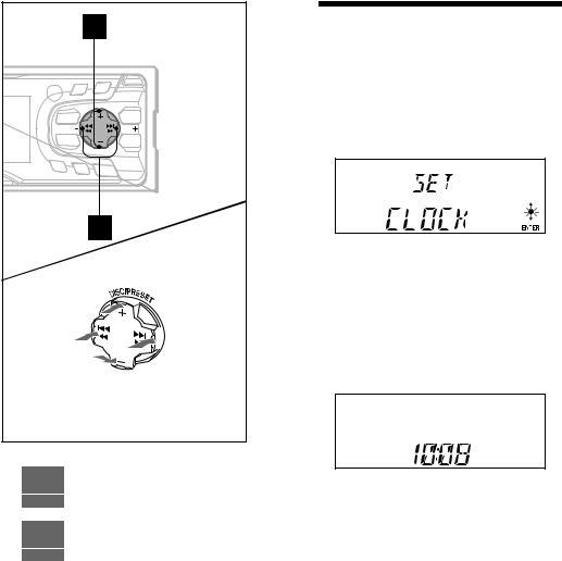
(DISC/PRESET) |
|
(+): to select upwards |
|
(SEEK) |
(SEEK) |
(–):to select |
(+):to select |
leftwards/. |
rightwards/> |
(DISC/PRESET)
(–): to select downwards
In menu mode, the currently selectable button (s) of these four are indicated with a “ M” in the display.
uDISC/PRESET buttons (+/–)
CD/MD 9, 11
RADIO 13, 14, 18
MENU 8, 10, 11, 12, 13, 17, 18, 21
vSEEK buttons (–/+)
CD/MD |
9 |
RADIO |
13, 14, 16 |
MENU |
8, 10, 12, 18, 20, 21 |
Setting the clock
The clock uses a 12-hour (US model) or 24-hour (AEP, UK models) digital indication.
Example: To set the clock to 10:08
1 Press (MENU), then press either side of (DISC/PRESET) repeatedly until “CLOCK” appears.
1Press (ENTER).
The hour indication flashes.
2Press either side of (DISC/PRESET) to set the hour.
3Press the (+) side of (SEEK).
The minute indication flashes.
4Press either side of (DISC/PRESET) to set the minute.
2 Press (ENTER).
The clock starts. After the clock setting is completed, the display returns to normal play mode.
Tips
•You can set the clock automatically with the RDS feature (page 18).
•When D.INFO mode is set to ON, the time is always displayed (page 21).
4
MDX-CA680/CA680X
2 A |
|
|
AUDIO OUT FRONT |
|
AUDIO OUT REAR |
B |
BUS AUDIO IN |
|
BUS CONTROL IN |
|
BUS AUDIO IN |
|
TV tuner unit* |
|
Syntoniseur de télévision* |
|
BUS CONTROL IN |
|
Source selector* |
|
Sélecteur de source* |
|
* not supplied |
|
non fournis |
(US model)
Cautions
•This unit is designed for negative ground 12 V DC operation only.
•Do not get the wires under a screw, or caught in moving parts (e.g. seat railing).
•Before making connections, disconnect the ground terminal of the car battery to avoid short circuits.
•Connect the yellow and red power input leads only after all other leads have been connected.
•Run all ground wires to a common ground point.
•Be sure to insulate any loose unconnected wires with electrical tape for safety.
•The use of optical instruments with this product will increase eye hazard.
Notes on the power supply cord (yellow)
•When connecting this unit in combination with other stereo components, the connected car circuit’s rating must be higher than the sum of each component’s fuse.
•When no car circuits are rated high enough, connect the unit directly to the battery.
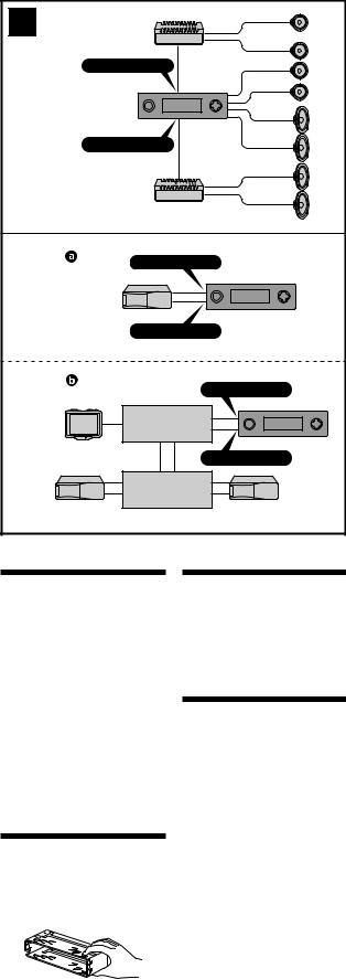
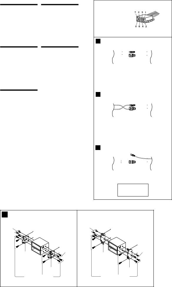
Parts Iist (1)
The numbers in the list are keyed to those in the instructions.
Caution
Handle the bracket 1 carefully to avoid injuring your fingers.
Connection example (2)
Notes (2-A)
•Be sure to connect the ground cord before connecting the amplifier.
•If you connect an optional power amplifier and do not use the built-in amplifier, the beep sound will be deactivated.
Tip (2-B-  )
)
For connecting two or more changers, the source selector XA-C30 (optional) is necessary.
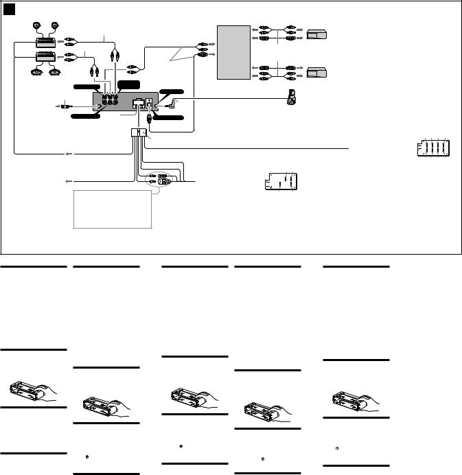
Connection diagram (3)
1To a metal surface of the car
First connect the black ground lead, then connect the yellow and red power input leads.
2To the power antenna control lead or power supply lead of antenna booster amplifier
Notes
•It is not necessary to connect this lead if there is no power antenna or antenna booster, or with a manually-operated telescopic antenna.
•When your car has a built-in FM/AM antenna in the rear/side glass, see “Notes on the control and power supply leads.”
3To AMP REMOTE IN of an optional power amplifier
This connection is only for amplifiers. Connecting any other system may damage the unit.
4To the interface cable of a car telephone
5To the +12 V power terminal which is energized in the accessory position of the ignition key switch
Notes
•If there is no accessory position, connect to the +12 V power (battery) terminal which is energised at all times.
Be sure to connect the black ground lead to it first.
•When your car has a built-in FM/AM antenna in the rear/side glass, see “Notes on the control and power supply leads.”
6To the +12 V power terminal which is energised at all times
Be sure to connect the black ground lead to it first.
5

MDX-CA680/CA680X
(US model)
3
Left
Gauche
Right
Droit
Left
Gauche
Right
Droit
RCA pin cord (not supplied)
Cordon à broche RCA (non fourni)
|
|
|
|
AUDIO OUT |
|
|
BUS AUDIO IN |
|
FRONT |
||
|
|
|
|||
|
|
|
|
L |
|
from car antenna adaptor |
|
|
R |
||
BUS |
AUDIO OUT |
AUDIO OUT |
|||
à partir de l’adaptateur de |
|||||
AUDIO |
REAR |
FRONT |
|||
l’antenne de la voiture |
|
|
|
||
|
|
AUDIO OUT |
Fuse (10 A) |
||
|
|
REAR |
|
Fusible (10 A) |
|
|
|
Blue/white striped |
|||
3 |
AMP REM |
Rayé bleu/blanc |
|||
Max. supply current 0.3 A |
|
|
|||
|
|
|
|||
|
Courant max. fourni 0,3 A |
|
|
||
|
|
White |
|
||
|
|
Blanc |
|
||
|
|
White/black striped |
|||
|
|
Rayé blanc/noir |
|||
|
|
Gray |
|
||
|
|
Gris |
|
||
|
|
Gray/black striped |
|||
|
|
Rayé gris/noir |
|||
|
|
Green |
|
||
|
|
Vert |
|
||
|
|
Green/black striped |
|||
|
|
Rayé vert/noir |
|||
|
|
Purple |
|
||
|
|
Mauve |
|
||
|
|
Purple/black striped |
|||
|
|
Rayé mauve/noir |
|||
Supplied with XA-C30
Fourni avec le XA-C30
REMOTE
IN
*
BUS
CONTROL IN
8
|
|
|
|
|
|
|
|
|
|
|
|
|
|
|
|
|
|
|
|
|
|
|
|
|
|
|
|
|
|
|
|
|
|
|
|
|
|
|
|
Source selector |
Supplied with the CD/MD changer |
||||||
Sélecteur de source |
Fourni avec le changeur de CD/MD |
||||||
|
|
|
|
|
|
|
|
|
|
|
|
|
|
|
|
|
|
|
|
|
|
|
|
|
|
|
|
|
|
|
|
|
|
|
|
|
|
|
|
|
|
|
|
|
|
|
|
* Insert with the cord upwards.
Insérez avec le câble vers le haut.
Black |
|
|
|
Noir |
|
|
1 |
|
|
|
|
Blue |
ANT REM |
|
|
Bleu |
2 |
||
|
Max. supply current 0.1 |
A |
|
|
|
||
|
Courant max. fourni 0,1 |
A |
|
Light blue
Bleu ciel ATT
4
Red
Rouge
5
Yellow
Jaune
6
Notes on the control and power supply leads
•The power antenna control lead (blue) supplies +12 V DC when you turn on the tuner.
•When your car has built-in FM/AM antenna in the rear/side glass, connect the power antenna control lead (blue) or the accessory power input lead (red) to the power terminal of the existing antenna booster. For details, consult your dealer.
•A power antenna without relay box cannot be used with this unit.
Memory hold connection
When the yellow power input lead is connected, power will always be supplied to the memory circuit even when the ignition key is turned off.
Notes on speaker connection
•Before connecting the speakers, turn the unit off.
•Use speakers with an impedance of 4 to 8 ohms, and with adequate power handling capacities to avoid its damage.
•Do not connect the speaker terminals to the car chassis, or connect the terminals of the right speakers with those of the left speaker.
•Do not connect the ground lead of this unit to the negative (–) terminal of the car.
•Do not attempt to connect the speakers in parallel.
•Connect only passive speakers. Connecting active speakers (with built-in amplifiers) to the speaker terminals may damage the unit.
•To avoid malfunction, do not use the built-in speaker wires installed in your car if its unit end share a common negative (–) lead for the right and left speakers.
•Do not connect the unit’s speaker cords to each other.
Précautions
•Cet appareil est exclusivement conçu pour fonctionner sur une tension de 12 V CC avec masse négative.
•Evitez de fixer des vis sur les câbles ou de coincer ceux-ci dans des pièces mobiles (par exemple, armature de siège).
•Avant d’effectuer les raccordements, débranchez la borne de terre de la batterie du véhicule pour éviter tout court-circuit.
•Raccordez les fils d’entrée d’alimentation jaune et rouge seulement après avoir terminé tous les autres raccordements.
•Rassemblez tous les fils de terre en un point de masse commun.
•Veillez à isoler avec du chatterton tout fil lâche non raccordé.
Remarques sur le cordon d’alimentation (jaune)
•Lorsque cet appareil est raccordé à d’autres éléments stéréo, la valeur nominale des circuits de la voiture raccordée doit être supérieure à la somme des fusibles de chaque élément.
•Si aucun circuit de la voiture n’est assez puissant, raccordez directement l’appareil à la batterie.
Liste des composants (1)
Les numéros de l’illustration correspondent à ceux des instructions.
Attention
Manipulez précautionneusement le support 1 pour éviter de vous blesser aux doigts.
Exemple de raccordement (2)
Remarques (2-A)
•Raccordez d’abord le fil de masse avant de raccorder l’amplificateur.
•Si vous raccordez un amplificateur de puissance indépendant et que vous n’utilisez pas l’amplificateur intégré, le bip sonore est désactivé.
Conseil (2-B- )
Dans le cas du raccordement de deux changeurs ou plus, le sélecteur de source XA-C30 (en option) est indispensable.
Schéma de raccordement (3)
1à un point métallique de la voiture
Branchez d‘abord le fil de masse noir et, ensuite, les fils d‘entrée d‘alimentation jaune et rouge.
2vers le fil de commande de l‘antenne électrique ou le fil d‘alimentation de l‘amplificateur d‘antenne
Remarques
•Il n'est pas nécessaire de raccorder ce fil s'il n'y a pas d'antenne électrique ni d'amplificateur d'antenne, ou avec une antenne télescopique manuelle.
•Si votre voiture est équipée d'une antenne FM/ AM intégrée dans la vitre arrière/latérale, voir “Remarques sur les fils de commande et d'alimentation”.
3au niveau du AMP REMOTE IN de l’amplificateur de puissance en option
Ce raccordement s’applique uniquement aux amplificateurs. Le branchement de tout autre système risque d’endommager l’appareil.
4vers le cordon de liaison d’un téléphone de voiture
5à la borne +12 V qui est alimentée quand la clé de contact est sur la position accessoires
Remarques
•S'il n'y a pas de position accessoires, raccordez la borne d'alimentation (batterie) +12 V qui est alimentée en permanence.
Raccordez d‘abord le fil de masse noir.
•Si votre voiture est équipée d'une antenne FM/ AM intégrée dans la vitre arrière/latérale, voir “Remarques sur les fils de commande et d'alimentation”.
6à la borne +12 V qui est alimentée en permanence
Raccordez d‘abord le fil de masse noir.
Remarques sur les fils de commande et d'alimentation
•Le fil de commande de l’antenne électrique (bleu) fournit une alimentation de + 12 V CC lorsque vous mettez l’appareil sous tension.
•Lorsque votre voiture est équipée d’une antenne FM/AM intégrée dans la vitre arrière/latérale, raccordez la sortie de commande de l’antenne (bleu) ou l’entrée d’alimentation des accessoires (rouge) au bornier de l’amplificateur d’antenne existant. Pour plus de détails, consultez votre revendeur.
•Une antenne électrique sans boitier de relais ne peut pas être utilisée avec cet appareil.
Raccordement pour la conservation de la mémoire
Lorsque le fil d’entrée d’alimentation jaune est raccordé, le circuit de la mémoire est alimenté en permanence même si la clé de contact est sur la position d’arrêt.
Remarques sur le raccordement des haut-parleurs
•Avant de raccorder les haut-parleurs, mettez l’appareil hors tension.
•Utilisez des haut-parleurs ayant une impédance de 4 à 8 ohms avec une capacité de manipulation adéquate pour éviter de les endommager.
•Ne raccordez pas les bornes du système de hautparleur au châssis de la voiture et ne raccordez pas les bornes du haut-parleur droit à celles du hautparleur gauche.
•Ne raccordez pas le câble de masse de cet appareil à la borne négative (–) de l’enceinte.
•N’essayez pas de raccorder les haut-parleurs en parallèle.
•Raccordez uniquement des haut-parleurs passifs. Le raccordement de haut-parleurs actifs (avec amplificateurs intégrés) aux bornes des hautparleurs peut endommager l’appareil.
•Pour éviter tout dysfonctionnement, n’utilisez pas les fils des haut-parleurs intégrés installés dans votre voiture si l’appareil partage un fil négatif commun (–) pour les haut-parleurs droit et gauche.
•Ne raccordez pas entre eux les cordons des hautparleurs de l’appareil.
6
MDX-CA680/CA680X
(AEP, UK Models)
3
|
|
*3 |
|
|
|
*3 |
|
|
|
|
AUDIO OUT |
|
|
BUS AUDIO IN |
FRONT |
from car aerial*1 |
|
6 |
L |
|
|
||
von Autoantenne*1 |
|
|
R |
de l’antenne de la voiture* |
1 |
AUDIO |
REAR FRONT |
|
BUS |
AUDIO OUT AUDIO OUT |
dall’antenna dell’auto*1 van een auto-antenne*1
AUDIO OUT REAR |
Fuse (10 A) |
|
Sicherung (10 A) |
||
|
||
|
Fusible (10 A) |
|
|
Fusibile (10 A) |
|
|
Zekering (10 A) |
Supplied with XA-C30 Mit dem XA-C30 geliefert Fourni avec le XA-C30
In dotazione con il modello XA-C30 Geleverd met de XA-C30
REMOTE IN
*2
BUS CONTROL IN
Source selector (not supplied)
Signalquellenwähler (nicht mitgeliefert)
Sélecteur de source (non fourni)
Selettore di fonte (non in dotazione)
Geluidsbronkiezer (niet bijgeleverd)
XA-C30
Supplied with the CD/MD changer Mit dem CD/MD-Wechsler geliefert Fourni avec le changeur de CD/MD In dotazione con il cambia CD/MD Geleverd met de CD/MD-wisselaar
*1 Note for the aerial connecting
If your car aerial is an ISO (International Organisation for Standardisation) type, use the supplied adaptor 6 to connect it.
First connect the car aerial to the supplied adaptor, then connect it to the aerial jack of the master unit.
*2 Insert with the cord upwards *3 RCA pin cord (not supplied)
*1 Hinweis zum Anschließen der Antenne
Wenn Ihre Fahrzeugantenne der ISO-Norm (ISO = International Organization for Standardization - Internationale Normungsgemeinschaft) entspricht, schließen Sie sie mit Hilfe des mitgelieferten Adapters 6 an.
Verbinden Sie zuerst die Fahrzeugantenne mit dem mitgelieferten Adapter, und verbinden Sie diesen dann mit der Antennenbuchse des Hauptgeräts.
*2 Mit dem Kabel nach oben einsetzen! *3 Cinchkabel (nicht mitgeliefert)
*1 Remarque sur le raccordement de l’antenne
Si votre antenne de voiture est de type ISO (organisation internationale de normalisation), utilisez l’adaptateur fourni 6 pour la raccorder.
Raccordez d’abord l’antenne de voiture à l’adaptateur fourni et, ensuite, à la prise d’antenne de l’appareil principal.
*2 Insérez avec le câble vers le haut *3 Cordon à broche RCA (non fourni)
*1 Nota per il collegamento dell’antenna
Se la vostra antenna della macchina è di tipo ISO (International Organization Standardization), utilizzare l’adattatore 6 in dotazione per collegarla.
Collegare prima l’antenna della macchina all’adattatore in dotazione, quindi collegarla alla presa dell’antenna dell’apparecchio principale.
*2 Inserire con il cavo rivolto verso l’alto *3 Cavo a piedini RCA (non in dotazione)
*1 Opmerking bij de antenne-aansluiting
Indien uw wagen is uitgerust met een antenne van het type ISO (International Organisation for Standardization), moet u die aansluiten met behulp van de meegeleverde adaptor 6.
Sluit eerst de auto-antenne aan op de meegeleverde adaptor en vervolgens de antennestekker op het hoofdtoestel.
*2 Inbrengen met het snoer naar boven *3 Tulpstekkersnoer (niet bijgeleverd)
Max. supply current 0.3 A max. Versorgungsstrom 0,3 A Courant max. fourni 0,3 A
Alimentazione massima fornita 0,3 A Max. voedingsstroom 0,3 A
Blue/white striped |
8 |
Blau-weiß gestreift |
|
ARayé bleu/blanc
A strisce blu e bianche
AMP REM |
Blauw/wit gestreept |
Light blue
Hellblau
BBleu ciel Azzurro
ATT |
Hemelsblauw |
See “Power Connection diagram” on the reverse side for details.
Näheres dazu finden Sie im “Stromanschlußdiagramm”. Blättern Sie dazu bitte um.
Voir le “Schéma de connexion d’alimentation” au verso pour plus de détails.
Per ulteriori informazioni, vedere “Diagramma dei collegamenti di alimentazione” che si trova sul retro.
Zie “Voedingsaansluitschema” op de achterkant voor meer details.
|
|
|
|
|
5 |
7 |
|
||
|
|
from the car’s power connector |
|
|
|
|
|
|
|
|
|
vom Stromanschluß des Fahrzeugs |
|
|
|
|
|
|
|
|
|
du connecteur d’alimentation de la voiture |
|
|
|
|
|
||
|
|
dal connettore di alimentazione dell’auto |
|
|
|
|
|
||
|
|
van de autovoedingsstekker |
|
|
|
|
|
|
|
|
|
|
|
4 |
8 |
|
|||
|
|
|
|
|
|
||||
|
|
|
|
|
|
||||
|
|
|
|
|
|
|
|
||
|
Yellow |
continuous power supply |
|
Red |
|
|
switched power supply |
||
|
Gelb |
permanente Stromversorgung |
|
Rot |
geschaltete Stromversorgung |
||||
4 |
Jaune |
alimentation continue |
7 |
Rouge |
|
alimentation commutée |
|||
|
Giallo |
alimentazione continua |
|
Rosso |
|
alimentazione commutata |
|||
|
Geel |
continu voeding |
|
Rood |
|
|
geschakelde voeding |
||
|
Blue |
power aerial control |
|
Black |
|
|
earth |
|
|
|
Blau |
Motorantenne |
|
Schwarz |
|
|
Masse |
|
|
5 |
Bleu |
antenne électrique |
8 |
Noir |
|
|
masse |
|
|
|
Blu |
comando dell’antenna elettrica |
|
Nero |
|
|
terra |
|
|
|
Blauw |
automatische antenne |
|
Zwart |
|
|
aarding |
|
|
|
|
|
|
|
|
|
|
|
|
Positions 1, 2, 3 and 6 do not have pins.
An Position 1, 2, 3 und 6 befinden sich keine Stifte.
Les positions 1, 2, 3 et 6 ne comportent pas de broches.
Le posizioni 1, 2, 3 e 6 non hanno piedini.
De posities 1, 2, 3 en 6 hebben geen pins.
|
|
|
|
|
|
|
|
|
1 |
3 |
5 |
7 |
|
||
|
|
|
|
from the car’s speaker connector |
|
|
|
|
|
|
|
|
|
||
|
|
|
|
|
|
|
|
|
|
|
|
||||
|
|
|
|
vom Lautsprecheranschluß des Fahrzeugs |
|
|
|
|
|
|
|
||||
|
|
|
|
du connecteur de haut-parleur de la voiture |
|
|
|
|
|
|
|
||||
|
|
|
|
dal connettore del diffusore dell’auto |
|
|
|
|
|
|
|
||||
|
|
|
|
van de autoluidsprekerstekker |
|
|
|
|
|
|
|
|
|
||
|
|
|
|
|
|
2 |
4 |
6 |
8 |
|
|||||
|
|
|
|
|
|
|
|
|
|
|
|||||
|
|
|
|
|
|
|
|
|
|
|
|||||
|
|
|
|
|
|
|
|
|
|
|
|
|
|||
|
|
|
|
Speaker, Rear, Right |
|
|
|
|
|
|
|
Speaker, Front, Left |
|||
|
|
+ |
|
Lautsprecher hinten rechts |
|
|
|
+ |
|
|
Lautsprecher vorne links |
||||
1 |
|
|
haut-parleur, arrière, droit |
5 |
|
|
|
|
haut-parleur, avant, gauche |
||||||
|
Purple |
|
|
Diffusore, posteriore, destro |
|
|
White |
|
|
Diffusore, anteriore, sinistro |
|||||
|
Violett |
|
|
Luidspreker, achter, rechts |
|
|
Weiß |
|
|
|
|
Luidspreker, voor, links |
|||
|
Mauve |
|
|
Speaker, Rear, Right |
|
|
Blanc |
|
|
|
|
Speaker, Front, Left |
|||
|
Viola |
|
|
|
|
Bianco |
|
|
|
|
|||||
2 |
Paars |
|
|
Lautsprecher hinten rechts |
|
|
Wit |
|
|
|
Lautsprecher vorne links |
||||
|
– |
|
haut-parleur, arrière, droit |
6 |
|
|
– |
|
|
haut-parleur, avant, gauche |
|||||
|
|
|
|
Diffusore, posteriore, destro |
|
|
|
|
|
Diffusore, anteriore, sinistro |
|||||
|
|
|
|
Luidspreker, achter, rechts |
|
|
|
|
|
|
|
Luidspreker, voor, links |
|||
|
|
|
|
Speaker, Front, Right |
|
|
|
|
|
|
|
Speaker, Rear, Left |
|||
|
|
|
|
Lautsprecher vorne rechts |
|
|
|
|
|
|
Lautsprecher hinten links |
||||
3 |
|
+ |
|
haut-parleur, avant, droit |
7 |
|
|
+ |
|
haut-parleur, arrière, gauche |
|||||
|
Grey |
|
|
Diffusore, anteriore, destro |
|
|
Green |
|
|
Diffusore, posteriore, sinistro |
|||||
|
Grau |
|
|
Luidspreker, voor, rechts |
|
|
Grün |
|
|
|
Luidspreker, achter, links |
||||
|
Gris |
|
|
Speaker, Front, Right |
|
|
Vert |
|
|
|
|
Speaker, Rear, Left |
|||
|
Grigio |
|
|
|
|
Verde |
|
|
|
|
|||||
|
Grijs |
|
|
Lautsprecher vorne rechts |
|
|
Groen |
|
|
|
Lautsprecher hinten links |
||||
4 |
|
– |
|
haut-parleur, avant, droit |
8 |
|
|
– |
|
haut-parleur, arrière, gauche |
|||||
|
|
|
|
Diffusore, anteriore, destro |
|
|
|
|
|
Diffusore, posteriore, sinistro |
|||||
|
|
|
|
Luidspreker, voor, rechts |
|
|
|
|
|
|
Luidspreker, achter, links |
||||
|
|
|
|
|
|
|
|
|
|
|
|
|
|
|
|
Negative polarity positions 2, 4, 6, and 8 have striped cords.
An den negativ gepolten Positionen (2, 4, 6 und 8) befinden sich gestreifte Adern.
Les positions de polarité négative 2, 4, 6 et 8 sont dotées de cordons rayés.
Le posizioni a polarità negativa 2, 4, 6 e 8 hanno cavi rigati.
De negatieve posities 2, 4, 6 en 8 hebben gestreepte kabels.
Cautions
• This unit is designed for negative earth 12 V DC operation only.
• Do not get the wires under a screw, or caught in moving parts (e.g. seat railing).
• Before making connections, turn the car ignition
off to avoid short circuits.
• Connect the power connecting cord 8 to the unit and speakers before connecting it to the auxiliary power connector.
• Run all earth wires to a common earth point.
• Be sure to insulate any loose unconnected wires with electrical tape for safety.
Notes on the power supply cord (yellow)
• When connecting this unit in combination with other stereo components, the connected car circuit’s rating must be higher than the sum of each component’s fuse.
• When no car circuits are rated high enough, connect the unit directly to the battery.
Parts list (1)
The numbers in the list are keyed to those in the instructions.
Caution
Handle the bracket 1 carefully to avoid injuring your fingers.
Vorsicht
• Dieses Gerät ist ausschließlich für den Betrieb bei 12 V Gleichstrom (negative Erdung) bestimmt.
• Achten Sie darauf, daß die Kabel nicht unter einer Schraube oder zwischen beweglichen Teilen wie z. B. in einer Sitzschiene eingeklemmt werden.
• Schalten Sie, bevor Sie irgendwelche Anschlüsse vornehmen, die Zündung des Fahrzeugs aus, um
Kurzschlüsse zu vermeiden.
• Verbinden Sie das Stromversorgungskabel 8 mit dem Gerät und den Lautsprechern, bevor Sie es mit dem Hilfsstromanschluß verbinden.
• Schließen Sie alle Erdungskabel an einen gemeinsamen Massepunkt an.
• Aus Sicherheitsgründen müssen alle losen, nicht angeschlossenen Drähte mit Isolierband abisoliert werden.
Hinweise zum Stromversorgungskabel (gelb)
• Wenn Sie dieses Gerät zusammen mit anderen Stereokomponenten anschließen, muß der Autostromkreis, an den die Geräte angeschlossen sind, eine höhere Leistung aufweisen als die Summe der Sicherungen der einzelnen Komponenten.
• Wenn kein Autostromkreis eine so hohe Leistung aufweist, schließen Sie das Gerät direkt an die Batterie an.
Teileliste (1)
Die Nummern in der Liste sind dieselben wie im Erläuterungstext.
Vorsicht
Seien Sie beim Umgang mit der Halterung 1 vorsichtig, damit Sie sich nicht die Hände verletzen.
Connection example (2)
Notes (2-A)
•Be sure to connect the earth cord before connecting the amplifier.
•If you connect an optional power amplifier and do not use the built-in amplifier, the beep sound will be deactivated.
Tip (2-B-  )
)
For connecting two or more CD/MD changers, the source selector XA-C30 (optional) is necessary.
Connection diagram (3)
ATo AMP REMOTE IN of an optional power amplifier
This connection is only for amplifiers. Connecting any other system may damage the unit.
BTo the interface cable of a car telephone
Warning
If you have a power aerial without a relay box, connecting this unit with the supplied power connecting cord 8 may damage the aerial.
Notes on the control leads
•The power aerial control lead (blue) supplies +12 V DC when you turn on the tuner or when you activate the AF (Alternative Frequency), TA (Traffic Announcement) function.
•When your car has built-in FM/MW/LW aerial in the rear/side glass, connect the power aerial control lead (blue) or the accessory power input lead (red) to the power terminal of the existing aerial booster. For details, consult your dealer.
•A power aerial without a relay box cannot be used with this unit.
Memory hold connection
When the yellow power input lead is connected, power will always be supplied to the memory circuit even when the ignition switch is turned off.
Notes on speaker connection
•Before connecting the speakers, turn the unit off.
•Use speakers with an impedance of 4 to 8 ohms, and with adequate power handling capacities to avoid its damage.
•Do not connect the speaker terminals to the car chassis, or connect the terminals of the right speakers with those of the left speaker.
•Do not connect the earth lead of this unit to the negative (–) terminal of the car.
•Do not attempt to connect the speakers in parallel.
•Connect only passive speakers. Connecting active speakers (with built-in amplifiers) to the speaker terminals may damage the unit.
•To avoid malfunction, do not use the built-in speaker wires installed in your car if its unit end share a common negative (–) lead for the right and left speakers.
•Do not connect the unit’s speaker cords to each other.
Anschluß beispiel (2)
Hinweise (2-A)
•Schließen Sie unbedingt zuerst das Massekabel an, bevor Sie den Verstärker anschließen.
•Wenn Sie einen gesondert erhältlichen Endverstärker anschließen und den integrierten Verstärker nicht benutzen, wird der Signalton deaktiviert.
Tip (2-B- )
Zum Anschließen von zwei oder mehr CD/MDWechslern wird der gesondert erhältliche Signalquellenwähler XA-C30 benötigt.
Anschluß diagramm (3)
AAn AMP REMOTE IN des gesondert erhältlichen Endverstärkers
Dieser Anschluß ist ausschließlich für Verstärker gedacht. Schließen Sie nichts anderes daran an. Andernfalls kann das Gerät beschädigt werden.
BAn Schnittstellenkabel eines Autotelefons
Warnung
Wenn Sie eine Motorantenne ohne Relaiskästchen verwenden, kann durch Anschließen dieses Geräts mit dem mitgelieferten Stromversorgungskabel 8 die Antenne beschädigt werden.
Hinweise zu den Steuerleitungen
•Die Motorantennen-Steuerleitung (blau) liefert + 12 V Gleichstrom, wenn Sie den Tuner
einschalten oder die AF- (Alternativfrequenzsuche) oder die TA-Funktion (Verkehrsdurchsagen) aktivieren.
•Wenn das Fahrzeug mit einer in der Heck-/ Seitenfensterscheibe integrierten FM (UKW)/MW/ LW-Antenne ausgestattet ist, schließen Sie die Motorantennen-Steuerleitung (blau) oder die Zubehörstromversorgungsleitung (rot) an den Stromversorgungsanschluß des vorhandenen Antennenverstärkers an. Näheres dazu erfahren Sie bei Ihrem Händler.
•Es kann nur eine Motorantenne mit Relaiskästchen angeschlossen werden.
Stromversorgung des Speichers
Wenn das gelbe Stromversorgungskabel angeschlossen ist, wird der Speicher stets (auch bei ausgeschalteter Zündung) mit Strom versorgt.
Hinweise zum Lautsprecheranschluß
•Schalten Sie das Gerät aus, bevor Sie die Lautsprecher anschließen.
•Verwenden Sie Lautsprecher mit einer Impedanz zwischen 4 und 8 Ohm und ausreichender Belastbarkeit. Ansonsten können die Lautsprecher beschädigt werden.
•Verbinden Sie die Lautsprecheranschlüsse nicht mit dem Wagenchassis, und verbinden Sie auch nicht die Anschlüsse des rechten mit denen des linken Lautsprechers.
•Verbinden Sie die Masseleitung dieses Geräts nicht mit dem negativen (–) Lautsprecheranschluß.
•Versuchen Sie nicht, Lautsprecher parallel anzuschließen.
•An die Lautsprecheranschlüsse dieses Geräts dürfen nur Passivlautsprecher angeschlossen werden. Schließen Sie keine Aktivlautsprecher (Lautsprecher mit eingebauten Verstärkern) an, da diese sonst beschädigt werden können.
•Um Fehlfunktionen zu vermeiden, verwenden Sie nicht die im Fahrzeug installierten, integrierten Lautsprecherleitungen, wenn am Ende eine gemeinsame negative (–) Leitung für den rechten und den linken Lautsprecher verwendet wird.
•Verbinden Sie nicht die Lautsprecherkabel des Geräts miteinander.
Précautions
• Cet appareil est conçu pour fonctionner sur courant continu de 12 V avec masse négative.
• Evitez de fixer des vis sur les câbles ou de coincer ceux-ci dans des pièces mobiles (par exemple, armature de siège).
• Avant d’effectuer des raccordements, éteignez le
moteur pour éviter les courts-circuits.
• Branchez le cordon d’alimention 8 sur l’appareil et les haut-parleurs avant de le brancher sur le connecteur d’alimentation auxiliaire.
• Rassemblez tous les fils de terre en un point de masse commun.
• Veillez à isoler avec du chatterton tout fil lâche non raccordé.
Remarques sur le cordon d’alimentation (jaune)
• Lorsque cet appareil est raccordé à d’autres éléments stéréo, la valeur nominale des circuits de la voiture raccordée doit être supérieure à la somme des fusibles de chaque élément.
• Si aucun circuit de la voiture n’est assez puissant, raccordez directement l’appareil à la batterie.
Liste des composants (1)
Les numéros de l’illustration correspondent à ceux des instructions.
Attention
Manipulez précautionneusement le support 1 pour éviter de vous blesser aux doigts.
Attenzione
• Questo apparecchio è stato progettato per l’uso solo a 12 V CC con massa negativa.
• Evitare che i cavi rimangano bloccati da una vite o incastrati nelle parti mobili (ad esempio nelle guide scorrevoli dei sedili).
• Prima di effettuare i collegamenti, spegnere il motore dell’automobile onde evitare di causare cortocircuiti.
• Collegare il cavo di collegamento dell’alimentazione 8 all’apparecchio e ai diffusori prima di collegarlo al connettore di alimentazione ausiliare.
• Portare tutti i cavi di massa a un punto di massa comune.
• Per sicurezza, assicurarsi di isolare qualsiasi cavo non collegato mediante apposito nastro.
Note sul cavo di alimentazione (giallo)
• Se questo apparecchio viene collegato con altri componenti stereo, la potenza nominale dei circuiti dell’automobile deve essere superiore a quella prodotta dalla somma dei fusibili di ciascun componente.
• Se la potenza nominale dei circuiti dell’automobile non è sufficiente, collegare l’apparecchio direttamente alla batteria.
Elenco dei componenti (1)
I numeri nella lista corrispondono a quelli riportati nelle istruzioni.
Attenzione
Maneggiare la staffa 1 con cautela per evitare di ferirsi le mani.
Let op!
• Dit apparaat is ontworpen voor gebruik op gelijkstroom van een 12 Volts auto-accu, negatief geaard.
• Zorg ervoor dat de draden niet onder een schroef of tussen bewegende onderdelen (b.v. zetelrail) terechtkomen.
• Alvorens aansluitingen te verrichten moet u het
contact afzetten om kortsluiting te vermijden.
• Sluit het netsnoer 8 aan op het toestel en de luidsprekers vooraleer u het op de hulpvoedingsaansluiting aansluit.
• Sluit alle aarddraden op een gemeenschappelijk aardpunt aan.
• Voorzie niet aangesloten draden om veiligheidsredenen altijd van isolatietape.
Opmerkingen bij de voedingskabel (geel)
• Wanneer u dit toestel aansluit samen met andere componenten, moet het vermogen van de aangesloten autostroomkring groter zijn dan de som van de zekeringen van elke component afzonderlijk.
• Wanneer het vermogen ontoereikend is, moet u het toestel rechtstreeks aansluiten op de batterij.
Onderdelenlijst (1)
De nummers in de afbeelding verwijzen naar die in de montage-aanwijzingen.
Voorzichtig
Houd de beugel 1 voorzichtig vast zodat u uw vingers niet verwondt.
Exemple de raccordement (2)
Remarques (2-A)
•Raccordez d’abord le fil de masse avant de raccorder l’amplificateur.
•Si vous raccordez un amplificateur de puissance indépendant et que vous n’utilisez pas l’amplificateur intégré, le bip sonore est désactivé.
Conseil (2-B- )
Dans le cas du raccordement de deux changeurs de CD/MD ou plus, le sélecteur de source XA-C30 (en option) est indispensable.
Schéma de raccordement (3)
AAu niveau du AMP REMOTE IN d’un amplificateur de puissance facultatif
Ce raccordement existe seulement pour les amplificateurs. Le raccordement à tout autre système peut endommager l’appareil.
BVers le cordon de liaison d’un téléphone de voiture
Avertissement
Si vous disposez d’une antenne électrique sans boîtier de relais, le branchement de cet appareil au moyen du cordon d’alimentation fourni 8 risque d’endommager l’antenne.
Remarques sur les fils de contrôle
•Le fil de commande (bleu) de l’antenne électrique assure une alimentation de
+12 V CC lorsque vous mettez le syntoniseur sous tension ou lorsque vous activez la fonction AF (fréquence secondaire) ou TA (informations routières).
•Lorsque votre voiture est équipée d’une antenne FM/MW/LW intégrée dans la vitre arrière/latérale, raccordez la sortie de commande de l’antenne (bleu) ou l’entrée d’alimentation des accessoires (rouge) au bornier de l’amplificateur d’antenne existant. Pour plus de détails, consultez votre revendeur.
•Une antenne électrique sans boitier de relais ne peut pas être utilisée avec cet appareil.
Raccordement pour la conservation de la mémoire
Lorsque le fil d’entrée d’alimentation jaune est raccordé, le circuit de la mémoire est alimenté en permanence même si la clé de contact est sur la position d’arrêt.
Remarques sur le raccordement des haut-parleurs
•Avant de raccorder les haut-parleurs, mettez l’appareil hors tension.
•Utilisez des haut-parleurs ayant une impédance de 4 à 8 ohms avec une capacité de manipulation adéquate pour éviter de les endommager.
•Ne raccordez pas les bornes du système de hautparleurs au châssis de la voiture et ne raccordez pas les bornes du haut-parleur droit à celles du haut-parleur gauche.
•Ne raccordez pas le câble de masse de cet appareil à la borne négative (–) de l’enceinte.
•N’essayez pas de raccorder les haut-parleurs en parallèle.
•Raccordez uniquement des haut-parleurs passifs. Le raccordement de haut-parleurs actifs (avec amplificateurs intégrés) aux bornes des hautparleurs peut endommager l’appareil.
•Pour éviter tout dysfonctionnement, n’utilisez pas les fils des haut-parleurs intégrés installés dans votre voiture si l’appareil partage un fil négatif commun (–) pour les haut-parleurs droit et gauche.
•Ne raccordez pas entre eux les cordons des hautparleurs de l’appareil.
Esempi di collegamento (2)
Note (2-A)
•Assicurarsi di collegare il cavo di terra prima di collegare l’apparecchio all’amplificatore.
•Se si collega un amplificatore di potenza opzionale e non si utilizza l’amplificatore incorporato, il segnale acustico verrà disattivato.
Suggerimento (2-B- )
Per collegare due o più cambia CD/MD, si deve utilizzare il selettore di fonte XA-C30 (opzionale).
Schema di collegamento (3)
AA AMP REMOTE IN di un amplificatore di potenza opzionale
Questo collegamento è riservato esclusivamente agli amplificatori. Non collegare un tipo di sistema diverso onde evitare di causare danni all’apparecchio.
BAl cavo interfaccia di un telefono per auto
Avvertenza
Quando si collega l’apparecchio con il cavo di alimentazione in dotazione 8, si potrebbe danneggiare l’antenna elettrica se questa non ha la scatola di relè.
Note sui cavi di controllo
•Il cavo di controllo dell’antenna elettrica (blu) fornisce corrente continua +12 V CC quando si accende il sintonizzatore o quando si attiva la funzione AF (frequenza alternativa) o TA (notiziario sul traffico).
•Se l’automobile è dotata di antenna FM/MW/LW incorporata nel vetro posteriore/laterale, collegare il cavo (blu) di controllo dell’antenna elettrica o il cavo (rosso) di ingresso dell’alimentazione opzionale al terminale di alimentazione del preamplificatore dell’antenna esistente. Per ulteriori informazioni, consultare il proprio fornitore.
•Non è possibile usare un’antenna elettrica senza scatola a relè con questo apparecchio.
Collegamento per la conservazione della memoria
Quando il cavo di ingresso alimentazione giallo è collegato, viene sempre fornita alimentazione al circuito di memoria anche quando la chiavetta a accensione è spenta.
Note sul collegamento dei diffusori
•Prima di collegare i diffusori spegnere l’apparecchio.
•Usare diffusori di impedenza compresa tra 4 e 8 ohm e con capacità di potenza adeguata, altrimenti i diffusori potrebbero venir danneggiati.
•Non collegare i terminali del sistema diffusori al telaio dell’auto e non collegare i terminali del diffusore destro a quelli del diffusore sinistro.
•Non collegare il cavo di terra di questo apparecchio al terminale negativo (–) del diffusore.
•Non collegare i diffusori in parallelo.
•Non collegare alcun diffusore attivo (con amplificatore incorporato) ai terminali dei diffusori dell’apparecchio perché si potrebbero danneggiare i diffusori attivi. Assicurarsi di collegare diffusori passivi a questi terminali.
•Per evitare problemi di funzionamento, non utilizzare i cavi dei diffusori incorporati installati nell’automobile se il terminale dell’apparecchio condivide un cavo comune negativo (–) per i diffusori destro e sinistro.
•Non collegare fra loro i cavi dei diffusori dell’apparecchio.
Voorbeeldaansluitingen (2)
Opmerkingen (2-A)
•Sluit eerst de massakabel aan alvorens de versterker aan te sluiten.
•Als u een los verkrijgbare vermogensversterker aansluit en de ingebouwde versterker niet gebruikt, is de pieptoon uitgeschakeld.
Tip (2-B- )
Om twee of meer CD/MD-wisselaars aan te sluiten, hebt u de geluidsbronkiezer XA-C30 (optioneel) nodig.
Aansluitschema (3)
ANaar AMP REMOTE IN van een los verkrijgbare vermogensversterker
Deze aansluiting is alleen bedoeld voor versterkers. Door een ander systeem aan te sluiten kan het toestel worden beschadigd.
BNaar het interface-snoer van een autotelefoon
Opgelet
Indien u een elektrische antenne heeft zonder relaiskast, kan het aansluiten van deze eenheid met het bijgeleverde netsnoer 8 de antenne beschadigen.
Opmerking betreffende de aansluitsnoeren
•De voedingskabel (blauw) van de elektrisch bediende antenne levert +12V gelijkstroom wanneer u de tuner aanschakelt of de functie AF (Alternative Frequency) of TA (Traffic Announcement) activeert.
•Wanneer uw auto is uitgerust met een FM/MW/ LW-antenne in de achterruit/voorruit, moet u de antennevoedingskabel (blauw) of de hulpvoedingskabel (rood) aansluiten op de voedingsingang van de bestaande antenneversterker. Raadpleeg uw dealer voor meer details.
•Met dit apparaat is het niet mogelijk een automatische antenne zonder relaishuis te gebruiken.
Instandhouden van het geheugen
Zolang de gele stroomdraad is aangesloten, blijft de stroomvoorziening van het geheugen intact, ook wanneer het contact van de auto wordt uitgeschakeld.
Opmerkingen betreffende het aansluiten van de luidsprekers
•Zorg dat het apparaat is uitgeschakeld, alvorens de luidsprekers aan te sluiten.
•Gebruik luidsprekers met een impedantie van 4 tot 8 Ohm en let op dat die het vermogen van de versterker kunnen verwerken. Als dit wordt verzuimd, kunnen de luidsprekers ernstig beschadigd raken.
•Verbind in geen geval de aansluitingen van de luidsprekers met het chassis van de auto en sluit de aansluitingen van de rechter en linker luidspreker niet op elkaar aan.
•Verbind de massakabel van dit toestel niet met de negatieve (–) aansluiting van de luidspreker.
•Probeer nooit de luidsprekers parallel aan te sluiten.
•Sluit geen actieve luidsprekers (met ingebouwde versterkers) aan op de luidspreker-aansluiting van dit apparaat. Dit zal leiden tot beschadiging van de actieve luidsprekers. Sluit dus altijd uitsluitend luidsprekers zonder ingebouwde versterker aan.
•Om defecten te vermijden mag u de bestaande luidsprekerbedrading in uw auto niet gebruiken wanneer er een gemeenschappelijke negatieve (–) draad is voor de rechter en linker luidsprekers.
•Verbind de luidsprekerdraden niet met elkaar.
7
MDX-CA680/CA680X
4 |
A |
B |
1
c
2
5 1
1

2 |
3 |
|
4 |
Dashboard |
2 |
|
|
||||
|
|
|
|
Tableau de bord |
|
|
|
|
|
|
3 |
|
|
|
|
1 |
|
|
|
|
|
|
4 |
|
|
|
7 |
|
Fire wall |
|
|
5 |
5 |
|
Paroi ignifuge |
|
|
6 |
|
|
|
|
|
|
|
|
|
Bend these claws outward |
|
|
|
|
|
for a tight fit, if necessary. |
|
|
|
|
|
Pliez ces griffes pour assurer
une prise correcte si 6 nécessaire.
6 5
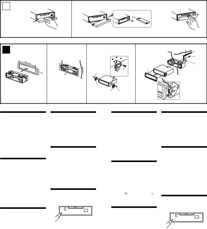
Precautions
•Choose the installation location carefully so that the unit will not interfere with normal driving operations.
•Avoid installing the unit in areas subject to dust, dirt, excessive vibration, or high temperatures, such as in direct sunlight or near heater ducts.
•Use only the supplied mounting hardware for a safe and secure installation.
Mounting angle adjustment
Adjust the mounting angle to less than 20° .
How to detach and attach the front panel (4)
Before installing the unit, detach the front panel.
4-A To detach
Before detaching the front panel, be sure to press (OFF). Press (OPEN), then slide the front panel to the right side, and pull out the left side.
4-B To attach
Place the hole  in the front panel onto the spindle
 on the unit as illustrated, then push the left side in.
Mounting example (5)
Installation in the dashboard
Mounting the unit in a Japanese car (6)
You may not be able to install this unit in some makes of Japanese cars. In such a case, consult your Sony dealer.
Note
To prevent malfunction, install only with the supplied screws 5.
Warning when installing in a car without ACC (accessory) position on the ignition key switch
Be sure to press(OFF) on the unit for two seconds to turn off the clock display after turning off the engine.
When you press (OFF) only momentarily, the clock display does not turn off and this causes battery wear.
RESET button
When the installation and connections are completed, be sure to press the RESET button with a ball-point pen, etc.
Précautions
•Choisissez soigneusement l’emplacement d’installation pour que l’appareil ne gêne pas le chauffeur pendant la conduite.
•Evitez d’installer l’appareil dans un endroit exposé à la poussière, à la saleté, à des vibrations excessives ou à des températures élevées comme en plein soleil ou à proximité de conduits de chauffage.
•Pour garantir un montage sûr, n’utilisez que le matériel fourni.
Réglage de l’angle de montage
Ajustez l’inclinaison à un angle inférieur à 20° .
Retrait et pose de la façade (4)
Avant d’installer l’appareil, retirez la façade.
4-A Pour retirer
Avant de retirer la façade, n’oubliez pas d’appuyer d’abord sur (OFF). Appuyez sur (OPEN), puis faites glisser la façade vers la droite et retirez-la par la gauche.
4-B Pour poser
Fixez la partie de la façade sur la partie de l’appareil, comme indiqué sur l’illustration, puis appuyez sur le côté gauche jusqu’au déclic.
Exemple de montage (5)
Installation dans le tableau de bord
Installation de l’appareil dans une voiture japonaise (6)
Cet appareil ne peut pas être installé dans certaines voitures japonaises. Consultez, dans ce cas, votre revendeur Sony.
Remarque
Pour éviter tout dysfonctionnement, utilisez uniquement les vis 5 pour le montage.
Avertissement en cas d’installation dans une voiture dont le contact ne comporte pas de position ACC (accessoires)
N’oubliez pas d’appuyer sur le bouton (OFF) de l’appareil pendant deux secondes après avoir coupé le moteur de façon à désactiver l’affichage de l’horloge.
Si vous appuyez brièvement sur (OFF), l’affichage de l’horloge n’est pas désactivé, ce qui provoque une usure de la batterie.
Touche RESET
Quand l’installation et les raccordements sont terminés, appuyez sur la touche RESET avec un stylo à bille, etc.
8
(AEP, UK models)
Power connection diagram
Auxiliary power connector may vary depending on the car. Check your car’s auxiliary power connector diagram to make sure the connections match correctly. There are three basic types (illustrated below). You may need to switch the positions of the red and yellow leads in the car stereo’s power connecting cord.
After matching the connections and switched power supply leads correctly, connect the unit to the car’s power supply. If you have any questions and problems connecting your unit that are not covered in this manual, please consult the car dealer.
Diagramma dei collegamenti di alimentazione
Il connettore di alimentazione ausiliaria può variare a seconda della macchina.
Controllare il diagramma del connettore di alimentazione ausiliaria della macchina per essere sicuri che le connessioni corrispondano correttamente. Vi sono tre tipi di base (illustrazione sotto). Potrà essere necessario cambiare le posizioni dei conduttori rosso e giallo nel cavo di alimentazione dello stereo della macchina. Dopo aver fatto corrispondere le connessioni e i cavi di alimentazione commutata, collegare l’apparecchio all’alimentazione della macchina. Se si hanno domande o se sorgono problemi che non sono stati trattati nel manuale nel collegare l’apparecchio, contattare l’autoconcessionario.
Stromanschluß diagramm
Der Hilfsstromanschluß kann je nach Fahrzeugtyp unterschiedlich sein. Sehen Sie im Hilfsstromanschlußdiagramm für Ihr Fahrzeug nach, wie die Verbindung ordnungsgemäß vorgenommen werden muß. Es gibt, wie unten abgebildet, drei grundlegende Typen.
Sie müssen möglicherweise die rote und gelbe Leitung des Stromversorgungskabels der Autostereoanlage vertauschen.
Stellen Sie die Anschlüsse her, schließen Sie die geschalteten Stromversorgungsleitungen richtig an, und verbinden Sie dann das Gerät mit der Stromversorgung Ihres Fahrzeugs. Wenn beim Anschließen des Geräts Fragen oder Probleme auftreten, die in dieser Bedienungsanleitung nicht erläutert werden, wenden Sie sich bitte an den Autohändler.
Schéma de connexion d’alimentation
Le connecteur d’alimentation auxiliaire peut varier suivant le type de voiture. Vérifiez le schéma du connecteur d’alimentation auxiliaire de votre voiture pour vous assurer que les connexions correspondent. Il en existe trois types de base (illustrés ci-dessous). Il se peut que vous deviez commuter la position du fil rouge et jaune du cordon d’alimentation de l’autoradio.
Après avoir établi les connexions et commuté correctement les fils d’alimentation, raccordez l’appareil à l’alimentation de la voiture. Si vous avez des questions ou des difficultés à propos de cet appareil qui ne sont pas abordées dans le présent mode d’emploi, consultez votre revendeur automobile.
Voedingsaansluitschema
De hulpvoedingsaansluiting kan verschillen naargelang van de wagen. Controleer het voedingsaansluitschema dat bij dit toestel wordt geleverd om te zien of de aansluitingen kloppen. Er zijn drie basistypes (zie illustratie hieronder).
Als de aansluitingen en geschakelde voedingskabels kloppen, sluit u het toestel aan op de voeding van de wagen. Indien u nog vragen of problemen hebt in verband met het aansluiten van het toestel die niet in deze handleiding vermeld staan, raadpleeg dan de autodealer.
MDX-CA680/CA680X
Auxiliary power connector
Hilfsstromanschluß
Connecteur d’alimentation auxiliaire
Connettore di alimentazione ausiliare
Hulpvoedingsaansluiting
|
Red |
|
|
Red |
|||
|
Rot |
|
|
Rot |
|||
|
Rouge |
|
|
Rouge |
|||
|
Rosso |
|
|
Rosso |
|||
|
Rood |
|
|
Rood |
|||
|
|
|
|
|
|
|
|
|
|
|
|
|
|
|
|
|
|
|
|
|
|
|
|
|
|
|
|
|
|
|
|
|
|
|
|
|
|
|
|
|
|
|
|
|
Yellow |
|
|
Yellow |
|
|||
|
|
|
|
|
Gelb |
|
|
Gelb |
|
|||
|
|
|
|
|
Jaune |
|
|
Jaune |
|
|||
|
|
|
|
|
Giallo |
|
|
Giallo |
|
|||
|
|
|
|
|
Geel |
|
|
Geel |
|
|||
|
|
|
|
|
|
|
|
|
|
|
|
|
|
|
Yellow |
continuous power supply |
|
Red |
|
switched power supply |
|
||||
|
|
Gelb |
permanente Stromversorgung |
|
Rot |
geschaltete Stromversorgung |
|
|||||
|
4 |
Jaune |
|
alimentation continue |
7 |
Rouge |
|
alimentation commutée |
|
|||
|
|
Giallo |
alimentazione continua |
|
Rosso |
alimentazione commutata |
|
|||||
|
|
Geel |
|
continu voeding |
|
Rood |
|
geschakelde voeding |
|
|||
|
|
|
|
|
|
|
|
|
|
|
|
|
|
|
|
|
Red |
|
|
Red |
|
||||
|
|
|
|
Rot |
|
|
Rot |
|
||||
|
|
|
|
Rouge |
|
|
Rouge |
|
||||
|
|
|
|
Rosso |
|
|
Rosso |
|
||||
|
|
|
|
Rood |
|
|
Rood |
|
||||
|
|
|
|
|
|
|
|
|
|
|
|
|
|
|
|
|
|
|
|
|
|
|
|
|
|
|
|
|
|
|
|
|
|
|
|
|
|
|
|
|
|
|
|
|
|
|
|
|
|
|
|
|
|
|
|
|
|
|
|
|
|
|
|
|
|
|
|
|
|
Yellow |
|
|
Yellow |
|
|||||
|
|
|
|
|
Gelb |
|
|
Gelb |
|
|||||
|
|
|
|
|
Jaune |
|
|
Jaune |
|
|||||
|
|
|
|
|
Giallo |
|
|
Giallo |
|
|||||
|
|
|
|
|
Geel |
|
|
Geel |
|
|||||
|
|
|
|
|
|
|
|
|
|
|
|
|
|
|
|
|
Yellow |
|
switched power supply |
|
Red |
|
continuous power supply |
|
|||||
|
4 |
Gelb |
geschaltete Stromversorgung |
7 |
Rot |
permanente Stromversorgung |
|
|||||||
|
Jaune |
alimentation commutée |
Rouge |
|
alimentation continue |
|
||||||||
|
|
Giallo |
alimentazione commutata |
|
Rosso |
|
alimentazione continua |
|
||||||
|
|
Geel |
|
geschakelde voeding |
|
Rood |
|
|
continu voeding |
|
||||
|
|
|
|
|
|
|
|
|
|
|
|
|
|
|
|
|
|
|
|
Red |
|
|
Red |
|
|||||
|
|
|
|
|
Rot |
|
|
Rot |
|
|||||
|
|
|
|
|
Rouge |
|
|
Rouge |
|
|||||
|
|
|
|
|
Rosso |
|
|
Rosso |
|
|||||
|
|
|
|
|
Rood |
|
|
Rood |
|
|||||
|
|
|
|
|
|
|
|
|
|
|
|
|
|
|
|
|
|
|
|
|
|
|
|
|
|
|
|
|
|
|
|
|
|
|
|
|
|
|
|
|
|
|
|
|
|
|
|
|
|
|
|
|
|
|
|
|
|
|
|
|
|
|
|
|
|
|
|
|
|
|
|
|
|
|
|
|
|
|
|
|
|
|
|
|
|
|
|
|
|
Yellow |
Yellow |
Gelb |
Gelb |
Jaune |
Jaune |
Giallo |
Giallo |
Geel |
Geel |
the car without ACC position Fahrzeug ohne Zubehörposition (ACC) Voiture sans position ACC
la macchina senza posizione ACC Wagen zonder ACC stand
6 A TOYOTA
5
max. size |
|
|
5 × 8 mm |
|
to dashboard/center console |
(7/32 × 11/32 |
in.) |
|
Dimension |
au tableau de bord/console centrale |
|
|
||
max. 5 × 8 mm |
|
|
(7/32 × 11/32 |
po.) |
|
Bracket |
5 |
|
|
max. size |
|||
Support |
|||
5 × 8 mm |
|||
|
|||
|
(7/32 × |
11/32 in.) |
|
|
Dimension |
||
|
max. 5 × 8 mm |
||
|
(7/32 × |
11/32 po.) |
|
|
Bracket |
|
|
|
Support |
|
|
Existing parts supplied with your car
Pièces existantes fournies avec la voiture
B NISSAN
5
max. size 5 × 8 mm
(7/32 × 11/32 in.)
Dimension max. 5 × 8 mm (7/32 × 11/32 po.)
to dashboard/center console
au tableau de bord/console centrale
|
5 |
Bracket |
max. size |
Support |
5 × 8 mm |
|
(7/32 × 11/32 in.) |
|
Dimension |
|
max. 5 × 8 mm |
|
(7/32 × 11/32 po.) |
|
Bracket |
|
Support |
Existing parts supplied with your car
Pièces existantes fournies avec la voiture
9
MDX-CA680/CA680X
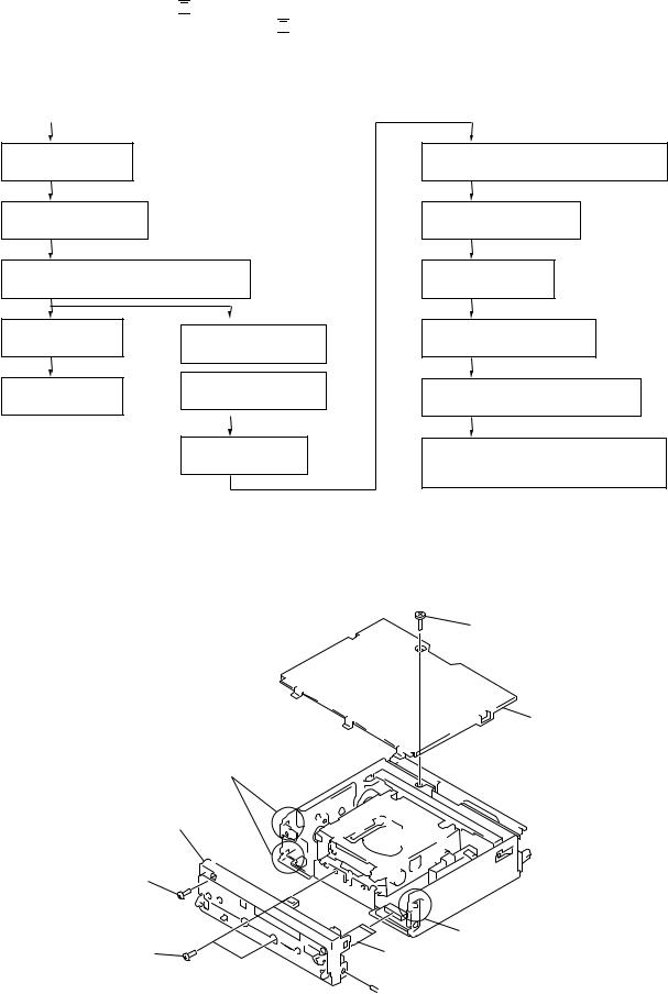
SECTION 2
DISASSEMBLY
• This set can be disassembled in the order shown below.
2-1. DISASSEMBLY FLOW
Note 1: The process described in 


 can be performed in any order.
Note 2: Without completing the process described in 

 , the next process can not be performed.
Note 3: Illustration of disassembly is omitted.
|
|
|
|
|
|
|
|
|
|
|
|
SET |
|
|
|
|
|
|
|
|
|
|
|
|
|
|
|
||
|
|
|
|
|
|
|
|
|
|
|
FRONT PANEL ASSY |
|
|
2-9. |
LO MOTOR ASSY (LOADING) (M903) |
||||
|
|
(Note 3) |
|
|
|
(Page 14) |
|||
2-2. |
SUB PANEL ASSY |
|
|
2-10. |
LEVER (LE23) ASSY |
||||
|
|
(Page 10) |
|
|
|
(Page 14) |
|||
2-3. |
MECHANISM DECK (MG-164MA-138) |
2-11. |
HOLDER ASSY |
||||||
|
|
(Page 11) |
|
|
|
(Page 15) |
|||
2-4. |
MAIN BOARD |
|
|
2-12. CHUCKING ARM ASSY |
|||||
2-6. |
SERVO BOARD |
||||||||
|
|
(Page 11) |
|
(Page 15) |
|||||
|
|
|
(Page 12) |
|
|||||
|
|
|
|
|
|
|
|
||
2-5. |
HEAT SINK |
2-7. MD COVER ASSY |
2-13. |
OPTICAL PICK-UP (KMS-241C) |
|||||
|
(Page 13) |
||||||||
|
|
(Page 12) |
|
|
(Page 16) |
||||
|
|
|
|
|
|||||
|
|
|
|
|
|
|
|
|
|
|
|
|
|
|
2-8. |
FLOAT BLOCK |
2-14. |
SL MOTOR ASSY (SLED) (M902), |
|
|
|
|
|
|
|
(Page 13) |
|
SP MOTOR ASSY (SPINDLE) (M901) |
|
|
|
|
|
|
|
|
|
(Page 16) |
|
Note: Follow the disassembly procedure in the numerical order given.
2-2. SUB PANEL ASSY
1 screw (PTT2.6 × 4)
2 cover
|
4 two claws |
|
5 sub panel assy |
|
|
3 screw |
|
|
(PTT2.6 × |
6) |
|
3 two screws |
4 claw |
|
|
||
(PTT2.6 × |
6) |
6 flexible flat (14 core) cable |
|
|
(CN701) |
 3 screw (PTT2.6 × 6)
10
MDX-CA680/CA680X
2-3. MECHANISM DECK (MG-164MA-138)
3two screws (PTT2.6 × 4)
4 bracket (MD)
5 mechanism deck (MG-164MA-138)
1 screw |
2 connector |
(PTT2.6 × 4) |
(CNP301) |
1 screw (PTT2.6 × 4)
2-4. MAIN BOARD
2 three screws  (PTT2.6 × 4)
1three ground point  screws (PTT2.6 × 6)
 3 main board
11
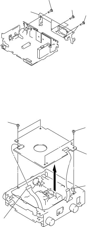
MDX-CA680/CA680X
2-5. HEAT SINK
1 screw (PTT2.6 × 10)
2 two screws
(PTT2.6 × 16)
3 heat sink
1 two screws (PTT2.6 × 10)
2-6. SERVO BOARD
2two screws (BVTT2 × 4)
2 two screws (BVTT2 × 4)
3 servo board
1 flexible flat (11core) cable (CN103)
1optical pick-up flexible board (CN102)
12

MDX-CA680/CA680X
2-7. MD COVER ASSY
1 four screws (BVTT2 × 4)
3 MD cover assy
shaft (MD cover guide)
cassette holder
A
2Pushing the cassette holder in the direction of the arrow A with a screwdriver, etc., disengage the shaft (MD cover guide) from
the slot in the MD cover assy.
Note: Take care not to scratch the optiocal pick-up when pushing the cassette holder with a screwdriver. etc.
2-8. FLOAT BLOCK
3Pushing an arrow A part, raise the float block up ward at the front to release a lock.
|
1 tension spring (float B) |
A |
5 two dampers assy |
6 float block
float block
5 two dampers assy
lever (lock R)
lever (lock L)
4
1 tension spring (float B)
2 two tension springs (float F)
13
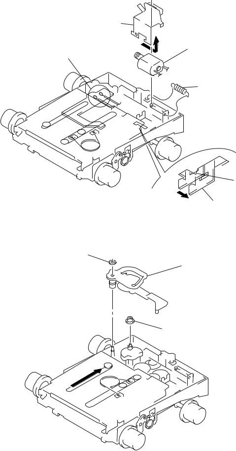
MDX-CA680/CA680X
2-9. LO MOTOR ASSY (LOADING) (M903)
4 Remove the bracket (LO)
in the direction of the arrow A. |
|
|
|
A |
5 LO motor assy (loading) |
1 Remove solders of motor (M903). |
|
|
|
(M903) |
2 tension spring (rack)
3 claw
bracket (LO)
– bottom view –
2-10. LEVER (LE23) ASSY
2 stopper washer
3 lever (LE23) assy
4 roller (gear E)
1
14
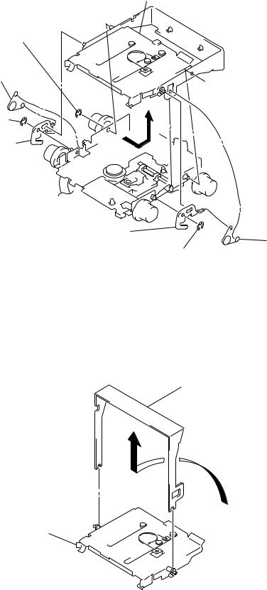
MDX-CA680/CA680X
2-11. HOLDER ASSY
4Remove the holder assy in the direction of the arrow.
2 type-E stop ring 1.5
1 spring (chucking)
 2 type-E stop ring 1.5
2 type-E stop ring 1.5
3 lever (lock R)
3 lever (lock L)
1 spring (chucking)
2 type-E stop ring 1.5
2-12. CHUCKING ARM ASSY
1 Remove the chucking arm assy in the direction of the arrow.
holder assy
15
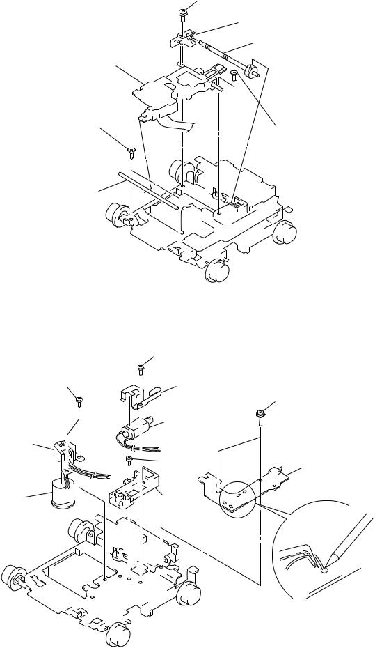
MDX-CA680/CA680X
2-13. OPTICAL PICK-UP (KMS-241C)
7 optical pick-up (KMS-241C)
1 two screws
(K2 × 3)
2 guide shaft (OPT L)
4screw (B2 × 3)
6 bearing (SL)
5 feed screw assy
3 screw
(K2 × 3)
2-14. SL MOTOR ASSY (SLED) (M902), SP MOTOR ASSY (SPINDLE) (M901)
|
4 screw |
|
|
|
(P1.7 × |
1.8) |
|
9 two screws |
|
|
|
(P1.7 × 1.8) |
5 bracket (SL) |
|
|
|
|
||
|
|
|
2 two screws |
|
|
|
(2 × 8) |
|
6 SL motor assy |
|
|
|
(sled) (M902) |
|
|
0 bracket (SP) |
|
|
|
|
7 screw |
|
3 sensor board |
|
(B2 × |
3) |
|
|
|
||
qa SP motor assy |
8 base (SL) |
|
|
(spindle) (M901) |
|
||
|
|
|
|
1 Remove solders of motors (M901, M902).
16

MDX-CA680/CA680X
SECTION 3
ELECTRICAL ADJUSTMENTS
TEST MODE
This set have the test mode function.
<Set the Test Mode>
1.Turn ON the regulated power supply. (The clock is displayed)
Note: Press the [OFF] button, if the clock is not displayed.
2.Push the preset [4] button.
3.Push the preset [5] button.
4.Press the preset [1] button for more than two seconds.
5.Then the display indicates all lights, the test mode is set.
<Release the Test mode> 1. Push the [OFF] button.
MD SECTION
MD section adjustments are done automatically in this set.
TUNER SECTION
Tuner section adjustments are done automatically in this set.
17
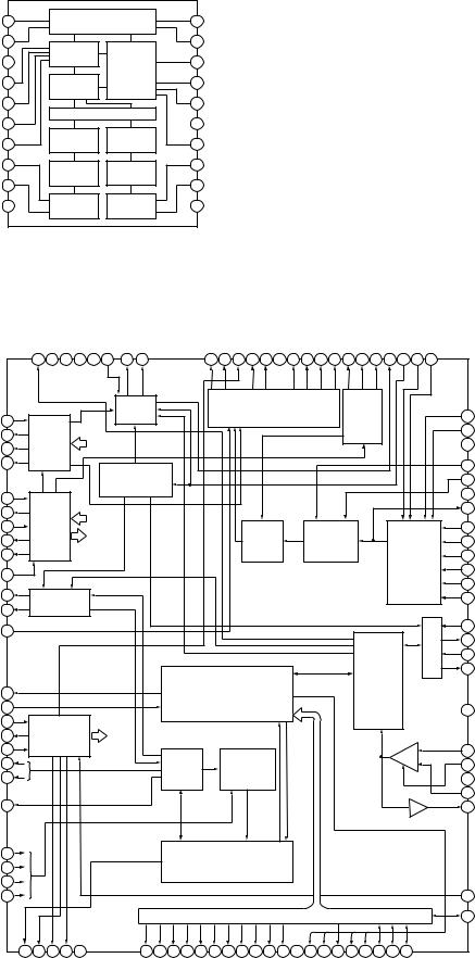
MDX-CA680/CA680X
SECTION 4
DIAGRAMS
• IC Block Diagrams
– SERVO Board –
IC101 PCM1718E/2K
XTI |
1 |
|
CLK |
20 |
XTO |
|
CONTROL |
||||||
|
|
|
|
|||
DGND |
2 |
INPUT |
|
19 |
CLKO |
|
|
|
|
|
|
||
VDD |
3 |
INTERFACE |
MODE |
18 |
MUTE |
|
|
||||||
|
|
|
|
|
||
LRCIN |
4 |
DIGITAL |
CONTROL |
17 |
DM1 |
|
|
||||||
|
|
FILTER |
|
|
|
|
DIN |
5 |
|
|
16 |
DM0 |
|
NOISE SHAPER
BCKIN |
6 |
|
|
|
|
|
|
|
|
15 RSTB |
|
|
|
|
|
|
|
|
|
|
|
|
|
|
|
|
|
||
ZERO |
7 |
|
|
5 LEVEL |
|
5 LEVEL |
14 FORMAT |
|
|
|
|
|
|
|
|
|
|
|
|
|
|
|
|
||||||
|
|
DAC |
|
|
DAC |
|
|
|
|
|
|
|
|
|
|
|
|
|
|
|
|
||||||||
D/C_R |
8 |
|
LOWPASS |
|
LOWPASS |
13 D/C_L |
|
|
|
|
|
|
|
|
|
|
|
|
|
|
|
|
|
||||||
|
|
|
|
|
|
|
|
|
|
|
|
|
|
|
|
|
|
|
|
|
|
|
|
||||||
VOUTR |
9 |
|
|
FILTER |
|
|
FILTER |
12 VOUTL |
|
|
|
|
|
|
|
|
|
|
|
|
|
|
|
|
|
||||
|
|
|
|
|
|
|
|
|
|
|
|
|
|
|
|
|
|
|
|
|
|
|
|
|
|||||
AGND |
10 |
|
|
CMOS |
|
|
CMOS |
11 |
VCC |
|
|
|
|
|
|
|
|
|
|
|
|
|
|
|
|
|
|
||
|
|
AMP |
|
|
AMP |
|
|
|
|
|
|
|
|
|
|
|
|
|
|
|
|
|
|
||||||
|
|
|
|
|
|
|
|
|
|
|
|
|
|
|
|
|
|
|
|
|
|
|
|
|
|
||||
IC301 |
CXD2662R |
|
|
|
|
|
|
|
|
|
|
|
|
|
|
|
|
|
|
|
|
|
|
|
|||||
|
|
EFMO |
DVSS |
TEST3 |
TEST2 |
TEST1 |
FGIN |
SPFD |
SPRD |
|
SFDR |
SRDR |
FS4 |
FRDR |
FFDR |
DVDD |
TFDR |
TRDR |
LDDR |
APCREF |
DTRF |
CKRF |
XLRF |
F0CNT |
ADFG |
APC |
DCHG |
|
|
|
|
100 |
99 |
98 |
97 |
96 |
95 |
94 |
93 |
|
92 |
91 |
90 |
89 |
88 |
87 |
86 |
85 |
84 |
83 |
82 |
81 |
80 |
79 |
78 |
77 |
76 |
|
|
|
|
|
|
|
|
|
|
SPINDLE |
|
|
|
|
|
PWM |
|
|
|
|
|
AUTO SEQUENCER |
|
|
|
|
|
|
|
||
MNT0 |
1 |
|
|
|
|
|
|
SERVO |
|
|
|
|
GENERATOR |
|
|
|
|
|
|
|
|
|
75 TE |
||||||
|
|
|
|
|
|
|
|
|
|
|
|
|
|
|
|
|
|
|
|
|
|
|
|
|
74 |
SE |
|||
MNT1 |
2 |
MONITOR |
|
EACH |
|
|
|
|
|
|
|
|
|
|
|
|
|
|
|
|
|
|
|
||||||
|
|
|
|
|
|
|
|
|
|
|
|
|
|
|
|
|
|
|
|
|
|
|
73 AVSS |
||||||
MNT2 |
3 |
CONTROL |
|
BLOCK |
|
|
|
|
|
|
|
|
|
|
|
|
|
|
|
|
|
|
|
|
|||||
MNT3 |
4 |
|
|
|
|
|
|
ADIP |
|
|
|
|
|
|
|
|
|
|
|
|
|
|
|
|
|
|
72 ADRB |
||
|
|
|
|
|
|
|
|
|
|
|
|
|
|
|
|
|
|
|
|
|
|
|
|
|
|
71 |
ADRT |
||
|
|
|
|
|
|
|
|
DECODER |
|
|
|
|
|
|
|
|
|
|
|
|
|
|
|
|
|
|
|||
|
|
|
|
|
|
|
|
|
|
|
|
|
|
|
|
|
|
|
|
|
|
|
|
|
|
70 AVDD |
|||
SWDT |
5 |
|
|
|
|
|
|
|
|
|
|
|
|
|
|
|
|
|
|
|
|
|
|
|
|
|
|
||
|
|
|
|
|
|
|
|
|
|
|
|
|
|
|
|
|
|
|
|
|
|
|
|
|
|
69 |
ADIO |
||
SCLK |
6 |
|
|
|
|
|
|
|
|
|
|
|
|
|
|
|
|
|
|
|
|
|
|
|
|
|
|
||
|
|
|
|
|
|
|
|
|
|
|
|
|
|
|
|
|
|
|
|
|
|
|
|
|
|
|
|
||
XLAT |
7 |
CPU I/F |
|
EACH |
|
|
|
|
|
|
|
|
|
|
|
|
|
|
|
|
|
|
|
|
68 |
VC |
|||
SRDT |
8 |
|
|
|
|
BLOCK |
|
|
|
|
|
SERVO |
|
|
|
|
A/D |
|
|
|
|
|
|
|
67 |
AUX1 |
|||
|
|
|
|
|
|
|
|
|
|
|
|
DSP |
|
|
CONVERTER |
|
|
|
|
|
|
||||||||
SENS |
9 |
|
|
|
|
|
|
|
|
|
|
|
|
|
|
|
|
|
ANALOG |
66 FE |
|||||||||
|
|
|
|
|
|
|
|
|
|
|
|
|
|
|
|
|
|
|
|
|
|
|
|||||||
XRST |
10 |
|
|
|
|
|
|
|
|
|
|
|
|
|
|
|
|
|
|
|
|
|
|
|
MUX |
|
65 ABCD |
||
|
|
|
|
|
|
|
|
|
|
|
|
|
|
|
|
|
|
|
|
|
|
|
|
|
|
||||
|
|
|
|
|
|
|
|
|
|
|
|
|
|
|
|
|
|
|
|
|
|
|
|
|
|
64 BOTM |
|||
|
|
|
|
|
|
|
|
|
|
|
|
|
|
|
|
|
|
|
|
|
|
|
|
|
|
|
|
||
SQSY |
11 |
SUBCODE |
|
|
|
|
|
|
|
|
|
|
|
|
|
|
|
|
|
|
|
|
|
|
|
63 PEAK |
|||
DQSY |
12 |
PROCESSOR |
|
|
|
|
|
|
|
|
|
|
|
|
|
|
|
|
|
|
|
|
|
|
|
|
|||
RECP |
13 |
|
|
|
|
|
|
|
|
|
|
|
|
|
|
|
|
|
|
|
|
|
|
|
|
|
|
62 |
CLTV |
|
|
|
|
|
|
|
|
|
|
|
|
|
|
|
|
|
|
|
|
|
|
|
|
|
|
61 |
FILO |
||
|
|
|
|
|
|
|
|
|
|
|
|
|
|
|
|
|
|
|
|
|
|
|
|
|
|
|
PLL |
||
|
|
|
|
|
|
|
|
|
|
|
|
|
|
|
|
|
|
|
|
|
|
|
|
|
|
|
60 |
FILI |
|
|
|
|
|
|
|
|
|
|
|
|
|
|
|
|
|
|
|
|
|
|
|
EFM/ACIRC ENCODER/ DECODER |
|
|
|
||||
|
|
|
|
|
|
|
|
|
|
|
|
|
|
|
|
|
|
|
|
|
|
|
|
|
59 PCO |
||||
XINT |
14 |
|
|
|
|
|
|
|
|
SHOCK RESISTANT |
|
|
|
|
|
|
|
|
|
|
|
||||||||
|
|
|
|
|
|
|
|
MEMORY CONTROLLER |
|
|
|
|
|
|
|
|
|
|
|
||||||||||
TX |
15 |
|
|
|
|
|
|
|
|
|
|
|
|
|
|
|
|
|
|
|
|||||||||
|
|
|
|
|
|
|
|
|
|
|
|
|
|
|
|
|
|
|
|
|
|
||||||||
|
|
|
|
|
|
|
|
|
|
|
|
|
|
|
|
|
|
|
|
|
|
|
|
|
|
58 AVSS |
|||
|
16 |
|
|
|
|
|
|
|
|
|
|
|
|
|
|
|
|
|
|
|
|
|
|
|
|
|
|
||
OSCI |
|
CLOCK |
|
|
EACH |
|
|
|
|
|
|
|
|
|
|
|
|
|
|
|
|
|
|
|
|
|
|||
OSCO |
17 |
|
|
|
|
|
|
|
|
|
|
|
|
|
|
|
|
|
|
|
|
|
|
|
|
||||
GENERATOR |
|
BLOCK |
|
|
|
|
|
|
|
|
|
|
|
|
|
|
|
|
|
|
|
|
|
||||||
XTSL |
18 |
|
|
|
|
|
|
|
|
|
|
|
|
|
|
|
|
|
|
|
|
57 |
RFI |
||||||
|
|
|
|
|
|
|
|
DIGITAL |
|
SAMPLING |
|
|
|
|
|
|
|
|
|
COMP |
|
||||||||
DIN0 |
19 |
|
|
|
|
|
|
|
|
|
|
|
|
|
|
|
|
|
|
|
56 |
BIAS |
|||||||
|
|
|
|
|
|
|
|
|
|
|
|
|
|
|
|
|
|
|
|
|
|||||||||
|
|
|
|
|
|
|
|
AUDIO |
|
|
RATE |
|
|
|
|
|
|
|
|
|
|
|
|
|
|||||
DIN1 |
20 |
|
|
|
|
|
|
|
|
|
|
|
|
|
|
|
|
|
|
|
|
|
|
|
55 |
AVDD |
|||
|
|
|
|
|
|
|
|
I/F |
|
CONVERTER |
|
|
|
|
|
|
|
|
|
|
|
|
|||||||
|
|
|
|
|
|
|
|
|
|
|
|
|
|
|
|
|
|
|
|
|
|
|
|
|
|
|
|
54 |
ASYI |
DOUT |
21 |
|
|
|
|
|
|
|
|
|
|
|
|
|
|
|
|
|
|
|
|
|
|
|
|
|
|
53 ASYO |
|
DATAI |
22 |
|
|
|
|
|
|
|
|
ATRAC |
|
|
|
|
|
|
|
|
|
|
|
|
|
||
LRCKI |
23 |
|
|
|
|
|
|
|
ENCODER/DECODER |
|
|
|
|
|
|
|
|
|
|
|
|
||||
XBCKI |
24 |
|
|
|
|
|
|
|
|
|
|
|
|
|
|
|
|
|
|
|
|
|
|
|
|
ADDT |
25 |
|
|
|
|
|
|
|
|
|
|
|
|
|
|
|
|
|
|
|
|
|
|
52 |
MVCI |
|
|
|
|
|
|
|
|
|
|
ADDRESS/DATA BUS A00 - A11, D0 - D3 |
|
|
|
51 |
D3 |
||||||||||
|
26 |
27 |
28 |
29 |
30 |
31 |
32 |
33 34 |
35 |
36 |
37 |
38 |
39 |
40 |
41 |
42 |
43 |
44 |
45 |
46 |
47 |
48 |
49 |
50 |
|
|
DADT |
LRCK |
XBCK |
FS256 |
DVDD |
A03 |
A02 |
A01 A00 |
A10 |
A04 |
A05 |
A06 |
A07 |
A08 |
A11 |
DVSS |
XOE |
XCAS |
A09 |
XRAS |
XWE |
D1 |
D0 |
D2 |
|
18
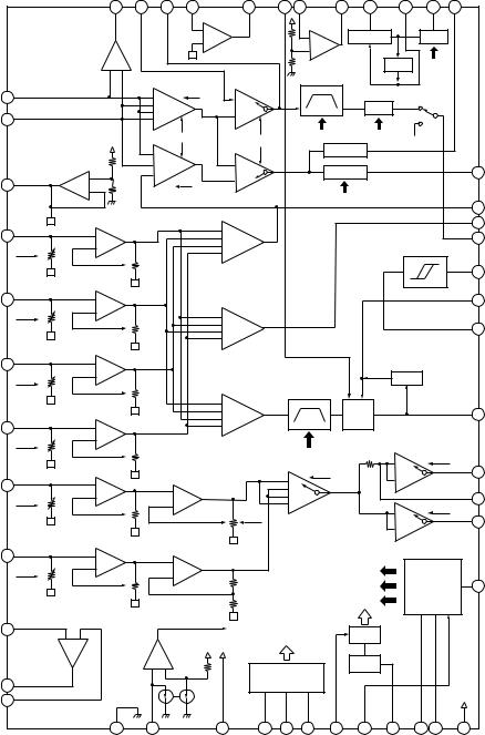
|
|
|
|
|
|
|
|
|
|
|
|
|
|
|
MDX-CA680/CA680X |
IC302 |
CXA2523AR |
|
|
|
|
|
|
|
|
|
|
|
|
|
|
|
|
MORFO |
MORFI |
RFO |
OPN |
OPO |
ADDC |
COMPP |
COMPO |
AGCI |
RF AGC |
|
RF |
PEAK |
|
|
|
48 |
47 |
46 |
45 |
44 |
43 |
42 |
41 |
40 |
39 |
|
38 |
37 |
|
|
|
|
|
|
USROP |
|
|
|
|
|
|
|
|
|
|
|
|
|
|
|
– |
|
|
+ |
|
RF AGC |
|
|
EQ |
|
|
|
|
|
|
|
+ |
|
|
|
|
|
|
|
|||
|
|
|
|
|
|
|
– |
|
|
|
|
|
|
|
|
|
|
RFA1 |
|
|
|
|
|
USRC |
|
|
|
|
|
|
|
|
|
|
|
|
|
|
|
|
DET |
|
EQ |
|
|
||
|
|
|
|
|
|
|
|
|
|
|
|
|
|||
|
|
+ – |
|
|
|
|
|
|
|
|
|
|
|
||
|
|
|
|
|
|
|
|
|
|
|
|
|
|
||
|
|
|
|
RFA2 |
RFA3 |
|
BPF3T |
|
|
|
|
|
|
||
I |
1 |
|
– |
|
|
|
PEAK3T |
|
AUX |
|
|
||||
|
1 |
HLPT |
–1 |
|
3T |
|
|
SW |
|
|
|||||
|
|
|
|
|
|
|
|
||||||||
|
|
|
– |
|
|
|
|
|
|
P-P |
|
|
|
|
|
|
|
|
– |
2 |
|
–2 |
|
|
|
|
|
|
|
|
|
J |
2 |
|
– |
|
|
|
|
|
|
|
|
|
|
||
|
|
|
|
OFST |
PTGR |
|
3T |
|
WBL |
TEMP |
|
|
|
||
|
|
|
|
|
|
|
|
PEAK |
|
|
|
|
|||
|
|
|
– |
1 |
|
|
|
|
|
|
|
|
|
|
|
|
|
|
|
–2 |
|
|
|
|
|
|
|
|
|
||
|
|
|
– |
|
|
|
|
|
|
|
|
|
|
||
|
CVB |
+ |
– |
2 |
|
–1 |
|
|
BOTTOM |
|
|
|
36 |
BOTM |
|
VC |
3 |
|
|
GRV |
|
|
|
PBH |
|
|
|
|
|||
– |
GRVA |
PBSW |
|
|
|
|
|
|
|
|
|
||||
|
|
|
|
|
WBL |
|
|
|
|
|
|
||||
|
|
|
|
|
|
|
|
|
|
35 |
ABCD |
||||
|
|
|
|
|
|
|
|
|
|
|
|
|
|
||
|
|
+ |
|
|
– |
|
|
|
|
|
|
|
|
34 |
FE |
A |
4 |
|
|
|
|
|
|
|
|
|
|
33 |
AUX |
||
|
|
– |
|
|
|
|
|
|
|
|
|||||
|
IVR |
– |
AA |
|
– |
|
|
|
|
|
|
BPFC |
|
|
|
|
|
– |
ABCDA |
|
|
|
|
|
|
||||||
|
|
|
|
|
|
|
|
|
|
|
|
|
|
||
|
|
|
|
|
|
|
|
|
|
|
|
|
|
32 |
ADFG |
B |
5 |
+ |
|
|
|
|
|
|
|
|
|
|
|
31 |
ADAGC |
|
IVR |
– |
BB |
|
+ |
|
|
|
|
|
|
|
|
|
|
|
|
|
|
|
+ |
|
|
|
|
|
|
|
|
30 |
ADIN |
|
|
|
|
|
– |
FEA |
|
|
|
|
|
|
|
||
|
|
|
|
|
– |
|
|
|
|
|
|
|
|
|
|
C |
6 |
+ |
|
|
|
|
|
|
|
|
|
|
|
|
|
|
IVR |
– |
CC |
|
|
|
|
|
|
|
DET |
|
|
|
|
|
|
|
|
|
|
|
|
BPF22 |
|
|
|
|
|
|
|
|
|
|
|
|
– |
|
|
|
ADIP |
|
|
|
|
|
|
|
|
|
|
|
– |
|
|
WBL |
|
|
|
29 |
ADFM |
||
|
|
|
|
|
+ |
ATA |
|
AGC |
|
|
|
||||
D |
7 |
+ |
|
|
|
|
|
|
|
|
|
||||
|
|
+ |
|
|
|
|
|
|
|
|
|
||||
|
IVR |
– |
DD |
|
|
|
|
|
|
|
|
|
|
|
|
|
|
|
|
|
|
|
|
WBL |
|
|
–1 |
|
|
TG |
|
|
|
|
|
|
|
|
|
|
|
|
|
|
SE |
||
|
|
|
|
|
|
|
– |
|
PTGR |
|
–2 |
|
|
28 |
|
E |
8 |
+ |
|
|
|
|
|
|
SEA |
|
|
||||
|
+ |
EE' |
|
|
|
|
|
|
|||||||
|
IVR |
– |
EE |
|
+ |
|
|
|
|
|
|
27 |
CSLED |
||
|
– |
|
|
– |
|
|
|
|
|
|
|||||
|
|
|
|
|
EFB |
+ |
TESW |
|
|
–1 |
|
|
TG |
|
|
|
|
|
|
|
|
|
|
|
|
|
TE |
||||
|
|
|
|
EBAL |
|
|
|
|
|
|
–2 |
|
|
26 |
|
|
|
|
|
|
ESW |
|
|
|
|
TEA |
|
|
|||
|
|
|
|
|
|
|
|
|
|
|
|
|
|||
|
|
|
|
|
|
|
|
|
|
|
|
|
|
|
|
F |
9 |
+ |
|
+ |
|
|
|
|
|
|
|
|
|
|
|
|
IVR |
– |
FF |
|
|
|
|
|
WBL |
|
|
|
|
|
|
|
– |
|
FF' |
|
|
|
|
|
|
|
|
||||
|
|
|
|
|
|
|
|
3T |
|
VI CONV |
25 |
WBLADJ |
|||
|
|
IV |
|
|
|
|
|
|
|
|
|||||
|
GSW |
|
FBAL |
|
|
|
|
|
EQ |
|
|
|
|
|
|
|
|
|
|
|
|
|
|
|
|
|
|
|
|||
PD |
10 |
|
|
|
AUXSW |
|
|
|
BGR |
|
|
|
|
|
|
|
+ |
– |
|
|
|
COMMAND |
|
|
|
|
|
|
|||
|
|
|
|
|
|
|
|
|
|
|
|||||
|
|
|
|
|
|
|
|
|
|
|
|
|
|
||
|
|
|
+ |
– |
|
SCRI - PARA |
|
VREF |
|
|
|
|
|
||
|
|
|
|
|
|
|
|
|
|
|
|
|
|||
APC |
11 |
|
|
|
|
DECODE |
|
|
|
|
|
|
|
||
APCREF |
12 |
|
|
|
|
|
|
|
|
|
|
|
|
|
|
|
|
13 |
14 |
|
15 |
16 |
17 |
18 |
19 |
20 |
21 |
22 |
23 |
24 |
|
|
|
GND |
TEMPI |
|
TEMPR |
SWDT |
SCLK |
XLAT |
XSTBY |
F0CNT |
VREF |
EQADJ |
3TADJ |
VCC |
|
|
|
|
|
|
|
|
|
|
|
|
|
|
|
|
19 |
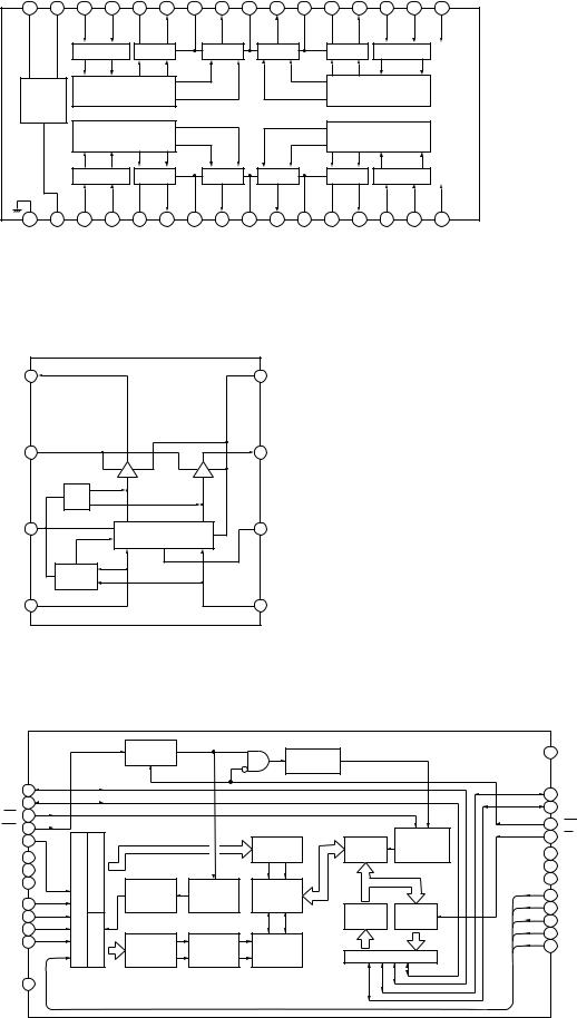
MDX-CA680/CA680X |
|
|
|
|
|
|
|
|
|
|
||||||
IC303 |
BH6518FS-E2 |
|
|
|
|
|
|
|
|
|
|
|
||||
|
CAPA– |
CAPA+ |
IN2R |
IN2F |
VM2 |
OUT2F |
PGND2 |
OUT2R |
VM12 |
OUT1R |
PGND1 |
OUT1F |
VM1 |
IN1F |
IN1R |
VDD |
|
32 |
31 |
30 |
29 |
28 |
27 |
26 |
25 |
24 |
23 |
22 |
21 |
20 |
19 |
18 |
17 |
|
|
|
INTERFACE |
AMP |
|
|
AMP |
|
AMP |
|
|
AMP |
INTERFACE |
VDD |
||
|
CHARGE |
|
PREDRIVE |
|
|
|
|
|
|
|
PREDRIVE |
|
|
|||
|
PUMP. |
|
|
|
|
|
|
|
|
|
|
|
|
|
|
|
|
|
OSC |
|
|
|
|
|
|
|
|
|
|
|
|
|
|
|
|
|
|
PREDRIVE |
|
|
|
|
|
|
|
PREDRIVE |
|
|
||
|
|
|
INTERFACE |
AMP |
|
|
AMP |
|
AMP |
|
|
AMP |
INTERFACE |
PSB |
||
|
1 |
2 |
3 |
4 |
5 |
6 |
7 |
8 |
9 |
10 |
11 |
12 |
13 |
14 |
15 |
16 |
|
GND |
VG |
IN4R |
IN4F |
VM4 |
OUT4F |
PGND4 |
OUT4R |
VM34 |
OUT3R |
PGND3 |
OUT3F |
VM3 |
IN3F |
IN3R |
PSB |
IC305 |
BA6287F |
|
|
|
|
|
|
|
|
|
|
|
|
|||
OUT1 |
1 |
|
|
|
|
|
|
|
8 |
GND |
|
|
|
|
|
|
VM |
2 |
|
|
|
|
|
|
|
7 |
OUT2 |
|
|
|
|
|
|
|
|
|
|
DRIVER |
|
DRIVER |
|
|
|
|
|
|
|
|
|
|
|
|
|
TSD |
|
|
|
|
|
|
|
|
|
|
|
|
|
VCC |
3 |
6 |
VREF |
|
|
CONTROL LOGIC |
|
|
|
POWER |
|
|
|
SAVE |
|
FIN |
4 |
5 |
RIN |
IC307 |
MSM51V4400E-70TS-K |
|
|
|
|
|
|
|||
|
|
|
|
TIMING |
|
TIMING |
|
|
26 |
VSS |
|
|
|
|
GENERATOR |
|
|
|
|||
|
|
|
|
|
|
|
|
|
||
|
|
|
|
|
|
GENERATOR |
|
|
|
|
DQ1 |
1 |
|
|
|
|
|
|
|
25 |
DQ4 |
DQ2 |
2 |
|
|
|
|
|
|
|
||
|
|
|
|
|
|
|
24 |
DQ3 |
||
WE |
3 |
|
|
|
|
|
|
|
||
|
|
|
|
|
|
|
23 |
CAS |
||
RAS |
4 |
|
|
|
|
|
|
WRITE |
||
|
|
|
|
|
|
22 |
OE |
|||
A9 |
5 |
|
|
|
|
COLUMN |
I/O |
|||
|
|
|
|
CLOCK |
21 |
NC |
||||
NC |
6 |
|
COLUMN |
|
|
DECODERS |
SELECTOR |
GENERATOR |
||
NC |
7 |
BUFFERS |
|
|
|
|
|
20 |
NC |
|
|
|
|
|
|
19 |
NC |
||||
NC |
8 |
INTERNAL |
REFRESH |
SENSE |
|
|
||||
|
|
|
A8 |
|||||||
|
|
ADDRESS |
CONTROL |
|
|
18 |
||||
|
|
AMPLIFIERS |
|
|
||||||
A0 |
9 |
ADDRESS |
|
|
|
|||||
|
COUNTER |
CLOCK |
|
|
17 |
A7 |
||||
|
|
INPUT |
OUTPUT |
|||||||
A1 |
10 |
|
|
|
|
16 |
A6 |
|||
|
|
|
|
BUFFERS |
BUFFERS |
|||||
A2 |
11 |
|
|
|
|
|||||
ROW |
|
|
|
|
|
15 |
A5 |
|||
A3 |
12 |
|
|
|
|
|
||||
ROW |
WORD |
MEMORY |
DATA BUS |
14 |
A4 |
|||||
|
|
|
|
DECODERS |
DRIVERS |
CELLS |
|
|
||
VCC |
13 |
|
|
|
|
|
|
|
|
|
20 |
|
|
|
|
|
|
|
|
|
|
Loading...