


Mini-disc Recorder
MDS-E12
Operating Instructions
Thank you very much for purchasing this Sony product. Sony products are designed with safety in mind. If electrical
products are used incorrectly, however, there is a risk of death or serious injury, so be sure to obey the following to avoid accidents.
2-347-245-11(1)
TABLE OF CONTENTS |
|
Warning ...................................... |
2 |
Location and Function of Parts |
5 |
Getting Started .......................... |
15 |
Recording on MDs .................... |
18 |
Playing MDs ............................... |
27 |
Editing Recorded MDs .............. |
40 |
Other Functions ........................ |
52 |
Rear Panel Terminal Function . 55 |
|
Operating the MD Recorder |
|
Using a Keyboard .................. |
59 |
Additinal Information ................ |
64 |
ã 2000 Sony Corporation
WARNING
Notice for the Customers in the United Kingdom
IMPORTANT
The wires in this mains lead are coloured in accordance with the following code:
Blue: Neutral Brown: Live
As the colours of the wires in the mains lead of this apparatus may not correspond with the coloured markings identifying the terminals in your plug, proceed as follows:
The wire which is coloured blue must be connected to the terminal which is marked with the letter N or coloured black.
The wire which is coloured brown must be connected to the terminal which is marked with the letter L or coloured red. Do not connect either wire to the earth terminal in the plug which is marked by the letter E or by the safety earth symbol I or coloured green or green-and-yellow.
For customers in the U.S.A.
To prevent fire or shock hazard, do not expose the unit to rain or moisture.
To avoid electrical shock, do not open the cabinet. Refer servicing to qualified personnel only.
This symbol is intended to alert the user to the presence of uninsulated “dangerous voltage” within the product’s enclosure that may be of sufficient magnitude to constitute a risk of electric shock to persons.
This symbol is intended to alert the user to the presence of important operating and maintenance (servicing) instructions in the literature accompanying the appliance.
CAUTION
You are cautioned that any changes or modification not expressly approved in this manual could void your authority to operate this equipment.
INFORMATION
This equipment has been tested and found to comply with the limits for a Class B digital device, pursuant to Part 15 of the FCC Rules. These limits are designed to provide reasonable protection against harmful interference in a residential installation. This equipment generates, uses, and can radiate radio frequency energy and, if not installed and used in accordance with the instructions, may cause harmful interference to radio communications.
However, there is no guarantee that interference will not occur in a particular installation. If this equipment does cause harmful interference to radio or television reception, which can be determined by turning the equipment off and on, the user is encouraged to try to correct the interference by one or more of the following measures:
•Reorient or relocate the receiving antenna.
•Increase the separation between the equipment and receiver.
•Connect the equipment into an outlet on a circuit different from that to which the receiver is connected.
•Consult the dealer or an experienced radio/TV technician for help.
For customers in the Europe.
The laser component in this product is capable of emitting radiation exceeding the limit for Class 1.
This appliance is classified as a CLASS 1 LASER product.
The CLASS 1 LASER PRODUCT MARKING is located on the rear exterior.
The following caution label is located inside the unit.
For customers in Canada
This ClassB digital apparatus complies With Canadian ICES-003.
CAUTION
TO PREVENT ELECTRIC SHOCK, DO NOT USE THS POLARIZED AC PLUG WITH AN EXTENSION CORD, RECEPTACLE OR OTHER OUTLET UNLESS THE BLADES CAN BE FULLY INSERTED TO PREVENT BLADE EXPOSURE.
ATTENTION
POUR PREVENIR LES CHOCS ELECTRIQUES, NE PAS UTILISER CETTE FICHE POLARISEE AVEC UNPROLONGATEUR, UNE PRISE DE COURANT OU UNE AUTRE SORITIE DE COURANT SAUF SI LES LAMES PEUVENT ETRE INSEREES A FOND SANS EN LAISSER AUCUNE PARTIE A DECOUVERT.
Setting the voltage selector (voltage selector equipped models only)
Check that the voltage selector on the rear panel is set to the local power line voltage. If not, set the selector to the correct position using a screwdriver before connecting the AC power cord to a wall outlet.
230V
120V
VOLTAGE
SELECTOR
Owner’s Record
The model and serial numbers are located on the rear of the unit. Record the serial number in the space provided below. Refer to them whenever you call upon your Sony dealer regarding this product.
Model No. ___________
Serial No. ___________
IN NO EVENT SHALL SELLER BE LIABLE FOR ANY DIRECT, INCIDENTAL OR CONSEQUENTIAL DAMAGES OF ANY NATURE, OR LOSSES OR EXPENSES RESULTING FROM ANY DEFECTIVE PRODUCT OR THE USE OF ANY PRODUCT.
2

Precautions
On safety
•Should any solid object or liquid fall into the cabinet, unplug the recorder and have it checked by qualified personnel before operating it any further.
•Caution – The use of optical instruments with this product will increase eye hazard.
On power sources
•Before operating the recorder, check that the operating voltage of the recorder is identical with your local power supply. The operating voltage is indicated on the nameplate at the rear of the recorder.
•The unit is not disconnected from the AC power source (mains) as long as it is connected to the wall outlet, even if the unit itself has been turned off.
•If you are not going to use the recorder for a long time, be sure to disconnect the recorder from the wall outlet. To disconnect the AC power cord, grasp the plug itself; never pull the cord.
•AC power cord must be changed only at the qualified service shop.
On condensation
If the recorder is brought directly from a cold to a warm location, or is placed in a very damp room, moisture may condense on the lenses inside the recorder. Should this occur, the recorder may not operate properly. In this case, remove the MD and leave the recorder turned on for several hours until the moisture evaporates.
On cleaning
Clean the cabinet, panel and controls with a soft cloth slightly moistened with mild detergent solution. Do not use any type of abrasive pad, scouring powder or solvent such as alcohol or benzine.
If you have any questions or problems concerning your recorder, please consult your nearest Sony dealer.
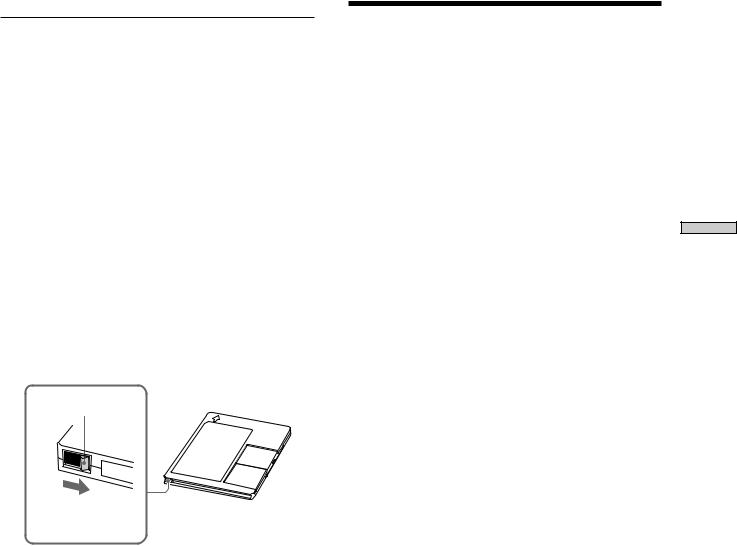
Handling MDs
The MD is enclosed in a cartridge to protect the disc from debris or fingerprints and to make it easy to handle. However, the presence of debris or a warped cartridge may inhibit the disc from operating properly. To ensure that you can always listen to the highest quality music, follow the precautions below:
•Do not touch the internal disc directly. Forcing the shutter open may damage the internal disc.
•Be sure to stick the labels supplied with the md to the appropriate positions. The shape of the labels may vary depending on the MD brand.
Proper Location |
Shutter |
|
of the labels |
||
|
Where to keep thge MDs
Do not place the cartridge where it may be exposed to direct sunlight or extremely high heat and humidity.
Regular maintenance
Wipe dust and debris from the surface of the cartridge with a dry cloth.
About This Manual
Conventions
•Controls in the instructions are those on the recorder; these may, however, be substituted by controls on the remote that are similarly named or, when
different, appear in the instructions within brackets.
•The following icons are used in this manual;
ZIndicates a procedure that requires use of the remote.
zIndicates tips for making the task easier and hints.
3

Parts of Function and Location
TABLE OF CONTENTS |
|
Location and Function of Parts ......... |
5 |
Front Panel Descriptions .............................................. |
6 |
Rear Panel Descriptions ................................................ |
7 |
Remote Descriptions ..................................................... |
8 |
Display Window Descriptions ................................... |
10 |
Using the Display Window ........................................ |
11 |
Getting Started ................................ |
14 |
After Unpacking .......................................................... |
14 |
Hooking Up the Audio Components........................ |
15 |
Setting the Clock .......................................................... |
17 |
Recording on MDs ............................ |
18 |
Recording on an MD ................................................... |
18 |
Notes on Recording ..................................................... |
19 |
Recording for long times ............................................ |
20 |
Adjusting the Recording Level .................................. |
21 |
Recording Tips ............................................................. |
22 |
Marking Track Numbers While Recording |
|
(Track Marking) ...................................................... |
23 |
Starting Recording With 6 Seconds of Prestored |
|
Audio Data (Time Machine Recording) .............. |
24 |
Synchro-recording With the Audio Component of |
|
Your Choice (Music Synchro-recording) ............ |
25 |
Synchro-recording With a Sony CD Player |
|
(CD Synchro-recording) ........................................ |
25 |
Playing MDs ...................................... |
27 |
Playing an MD ............................................................. |
27 |
Playing a Specific Track .............................................. |
29 |
Locating a Particular Point in a Track ....................... |
30 |
Playing Tracks Repeatedly (Repeat Play) ................. |
31 |
Playing Tracks in Random Order (Shuffle Play) ..... |
32 |
Creating Your Own Program (Program Play) ......... |
33 |
Storing the Located Track to Start Play |
|
Instantaneously (Multi-access Play) .................... |
34 |
Setting Play start position After Play Is Stopped |
|
(Resume Play) ......................................................... |
36 |
Returning to the Specified Point (Locate Play) ....... |
36 |
Pausing After Each Track (Auto Pause) ................... |
37 |
Making Track Play Start Soon (Auto Cue) ............... |
38 |
Changing Playback Speed |
|
(Variable Speed Play) ............................................. |
39 |
Editing Recorded MDs ..................... |
40 |
Before you start editing............................................... |
40 |
Erasing tracks (ERASE) ............................................... |
41 |
Combining Tracks (COMBINE) ................................. |
43 |
Moving Tracks (MOVE) .............................................. |
44 |
Dividing Tracks (DIVIDE) .......................................... |
45 |
Naming a Track or MD (NAME) ............................... |
46 |
Undoing the Last Edit (UNDO) ................................. |
50 |
Changing Recorded Level after Recording |
|
(S.F Edit) .................................................................. |
50 |
Other Functions ................................ |
52 |
Fade IN and Fade Out Z ............................................. |
52 |
Notification of the track end and the disc end |
|
(End Of Track/Disc) .............................................. |
53 |
Using a Timer ............................................................... |
54 |
Rear Panel Terminal Functions ........ |
55 |
Control terminal functions ......................................... |
55 |
Remote Terminal Functions ....................................... |
55 |
Parallel Input-Output .................................................. |
57 |
RS-232C ......................................................................... |
58 |
Operating the MD Recorder Using a |
|
Keyboard ........................................... |
59 |
Setting the keyboard ................................................... |
59 |
Naming a Track or MD Using the Keyboard ........... |
60 |
Operating the Recorder Through the Keyboard ..... |
61 |
Assigning Characters to Keyboard Keys.................. |
62 |
Keyboard Operations (English Keyboard Layout) . 63 |
|
Keyboard Operations (10-Keyboard Layout) .......... |
63 |
Additional Information.................... |
64 |
System Limitations ...................................................... |
64 |
Trouble shooting .......................................................... |
65 |
Self-Diagnosis Function .............................................. |
66 |
Display Messages ........................................................ |
67 |
Specifications ................................................................ |
68 |
Exterior dimensions .................................................... |
69 |
Edit Menu Table ........................................................... |
70 |
Setup Menu Table ........................................................ |
71 |
Last Mode Memory ..................................................... |
72 |
4

Location and
Function of Parts
5
Parts of Function and Location
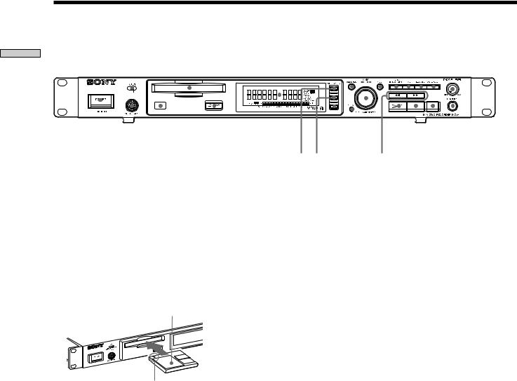
Front Panel Descriptions
1 2 |
3 |
4 |
567 89q;qa qs |
||||||||||||||
|
|
|
|
|
|
|
|
|
|
|
|
|
|
|
|
|
|
|
|
|
|
|
|
|
|
|
|
|
|
|
|
|
|
|
|
|
|
|
|
|
|
|
|
|
|
|
|
|
|
|
|
|
|
|
|
|
|
|
|
|
|
|
|
|
|
|
|
|
|
|
|
|
|
|
|
|
|
|
|
|
|
|
|
|
|
|
|
|
|
|
|
|
|
|
|
|
|
|
|
|
|
|
|
|
|
|
|
|
|
|
|
|
|
|
|
|
|
|
|
|
|
|
|
|
|
|
|
|
|
|
|
|
|
|
|
|
|
|
|
|
|
|
|
qd qf |
qg |
qh qj qk ql w; wa ws wd wf |
1POWER button
Press to turn the recorder on. When you press the button again, the recorder turns off.
2INPUT selector
Use to select the input jack (or connector) of the program source to be recorded.
3MD insertion slot
Insert the MD as illustrated below.
With the labeled side up
With the arrow pointing towards the recorder
4Display window
Shows various information.
5MENU/NO button
Press to display “Edit Menu” or “Setup Menu.” Also, the MENU mode is cleared.
6AMS control (MARK/ENTER button)
Turn to locate tracks, adjust the recording level, select the input characters, or select a menu item and a setting value.
7YES button
Press to carry out the selected operation.
8LEVEL/DISPLAY/CHAR button
Press to display INPUT or OUTPUT level and disc or track information, select the type of characters to be input, and change to time display.
9TIME button
Press to change time information on the disc or track.
0LOCATE button
Press to locate pre-marked positions.
!Á AUTO CUE button
Press to set AUTO CUE, AUTO PAUSE, or OFF.
!ª PHONE LEVEL control
Use to adjust the volume of the headphones.
!£ KEYBOARD jack
Connect a keyboard to this jack.
!¢ Remote sensor
Receives the infrared signal of the remote for remote operations.
!° Z EJECT button
Press to eject the MD.
!¤ VARI SPEED button
Press to turn on and off VARI SPEED.
!¦ VARI SPEED +button
Press to increase play speed at 0.5% step when VARI SPEED is on.
!¥ VARI SPEED _button
Press to decrease play speed at 0.5% step when VARI SPEED is on.
!» CLEAR button
Press to cancel the selection.
@¼ m/M (backward/forward) button
Press to lacate a portion whithin a track, change the contens of a program, or change the input character.
@Á 7 (play/pause) button
Press to start play and pause or resume play or recording.
@ª x (stop) button
Press to stop play or recording, or cancel the selected operation.
@£ z (record) button
Press to record on the MD, monitor the input signal, or mark track numbers.
@¢ PHONES jack
Connect headphones to this jack.
6
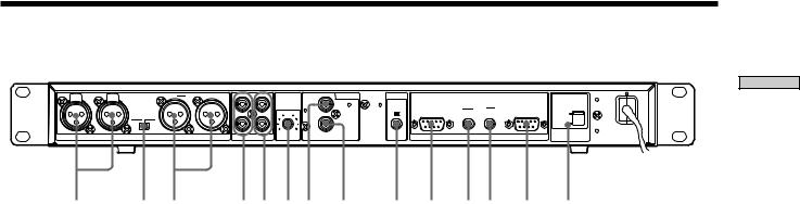
Rear of the Recorder
R |
PUSH |
IN |
PUSH |
L |
R |
OUT |
L |
|
|
ANALOG |
DIGITAL |
CTRL-S |
|
|
|
|
|
|
|
|
|
|
|
|
|
L |
INPUT |
IN |
|
|
|
|
|
|
|
|
|
|
|
|
|
|
LEVEL |
PARALLEL |
|
RELAY |
RS-232C |
|||
|
|
|
|
OUTPUT |
|
|
|
|
|
|
||||||
|
|
|
|
LEVEL |
|
|
IN |
OUT |
|
5 |
|
IN |
OUT |
IN |
230V |
|
|
|
|
|
+4dBu |
-10dBu |
|
|
|
|
|
|
|
|
|
|
120V |
|
|
|
|
|
|
|
|
|
R |
|
|
OUT |
|
|
|
|
|
|
|
|
|
|
|
|
|
|
0 |
10 |
COAXIAL |
|
REMOTE |
VOLTAGE |
|
|
|
|
|
ANALOG(BAL) |
|
|
ANALOG(UNBAL) |
|
|
|
SELECTOR |
|||||
12 3 45 67 8
1 ANALOG (BALANCE) input terminal (XLR type)
Inputs as an analog signal the sound of the component connected by an XLR connecting cable.
2OUTPUT LEVEL (BALANCE) selector
Changes the output level of the BALANCE.
3ANALOG (BALANCE) output terminal (XLR type)
Outputs as an analog signal the contents of the MD of this recorder to the component connected by an XLR connecting cable.
4ANALOG (UNBALANCE) input jacks
Inputs as an analog signal the sound of the component connected by a pin type connecting cable.
5ANALOG (UNBALANCE) output jacks
Outputs as an analog signal the contents of the MD of this recorder to the component connected by a pin type connecting cable.
6ANALOG INPUT LEVEL control
Can adjust the level of analog input in a range of _∞ ~ +15 dB.
Normally, this control is used in the position (0 dB) of center click.
7DIGITAL COAXIAL input jack
Inputs as a digital signal the sound of the connected component.
9 q; qaqs qd qf
8DIGITAL COAXIAL output jack
Outputs an a digital signal the contents of the MD of the recorder to the connected component.
9CONTROL-S jack
Connects the remote or control equipment.
If the plug is connected to the jack, the remote sensor does not receive infrared rays.
0PARALLEL connector
(D-sub 9-pin female)
Connects a component with simple circuits for the remote operations of the functions preset in the recorder.
!Á RELAY OUT connector
!ª REELAY IN connector
Plays or records successively by connecting multiple recorders and sending a control signal.
!£ RS-232C connector
(D-sub 9-pin male)
Connects a component that controls the recorder from outside.
!¢ VOLTAGE SELECTOR
(Except for the USA/CA models.)
Select 120V or 230V according to the local power line voltage. (Refer to page 2)
Parts of Function and Location
7

Remote Descriptions
|
|
|
|
|
|
|
|
wk |
|
|
|
|
|
Location |
|
|
EJECT |
|
|
|
|
|
|
|
|
|
qs |
and |
1 |
|
|
|
|
|
|
|
|
|
|
|
qd |
|
PLAY MODE |
|
|
|
|
|
|
|
qf |
||||
ofFunction |
|
|
|
|
|
|
|
|
|||||
2 |
M.ACCESS |
DISPLAY |
|
TIME |
MENU/NO |
|
YES |
|
|||||
|
|
|
|
|
|
qg |
|||||||
|
|
|
|
|
|
|
|
|
|
|
|
||
|
|
|
CONTINUE |
|
|
SHUFFLE |
PROGRAM |
|
DATE |
|
qh |
||
|
|
A |
|
B |
D |
|
E |
|
|||||
|
|
|
|
|
C |
|
|
|
|||||
|
|
|
|
|
|
|
|
|
RECORDED PRESENT |
|
|||
Parts |
|
F |
1 |
|
G |
2 |
H |
3 |
I |
4 |
J |
5 |
|
3 |
K |
6 |
|
L |
7 |
M |
8 |
N |
9 |
O |
10 |
|
|
|
|
P |
11 |
|
Q 12 |
R |
13 |
S |
14 |
T |
15 |
|
|
|
|
U |
16 |
|
V |
17 |
W 18 |
X |
19 |
Y |
20 |
|
|
|
|
Z |
21 |
|
- |
22 |
|
23 |
. |
24 |
, |
25 |
qj |
|
4 |
|
|
qk |
|||||||||
|
|
|
|
|
REPEAT |
|
A B |
|
A.CUE |
M.SCAN |
|||
|
5 |
|
>25 |
|
|
|
A.PAUSE |
|
|||||
|
/ |
? |
|
! |
|
|
|
|
|
ql |
|||
|
6 |
|
|
|
NAME IN |
|
|
|
CLEAR |
SCROLL |
|||
|
|
NAME |
|
|
CHAR |
|
NUM |
|
|
|
|
|
|
|
|
|
|
|
|
|
|
|
|
|
|
|
w; |
|
7 |
|
|
|
|
|
|
|
|
|
|
|
wa |
|
8 |
|
|
|
|
|
|
|
|
|
|
|
ws |
|
|
|
|
|
|
|
|
|
|
|
|
wd |
|
|
|
|
|
|
|
|
|
T.REC MUSIC SYNC |
|||||
|
9 |
|
|
|
|
|
|
wf |
|||||
|
|
|
|
|
|
|
|
|
|
|
|
||
|
|
|
|
|
CD-SYNC |
|
|
|
|
|
wg |
||
|
q; |
|
STOP |
|
|
START |
STANDBY |
|
|
|
|
||
|
|
|
|
|
|
|
|
|
|||||
|
|
|
|
|
|
|
|
|
|
|
|
wh |
|
|
qa |
|
|
|
CD PLAYER |
|
|
FADER |
|
|
|||
|
|
|
|
|
|
|
|
|
|
|
|
wj |
|
|
|
|
|
|
|
|
|
|
|
|
LEVEL |
||
|
|
|
|
|
|
|
|
|
|
RM-DR1 |
|
||
|
|
|
|
|
|
MINIDISC DECK |
|
|
|
||||
1Z (EJECT) button
Press to eject the MD.
2PLAY MODE button
Press to select multi-access, normal play, Shuffle Play, or Program Play.
3Letter/track number input buttons
Press to input letters, numbers, symbols or select track numbers.
4A ↔ B button
Press to select Repeat A ↔ B Play.
5REPEAT button
Press to select ALL repeat, one track repeat, or repeat off.
6NAME button
Press to add the name or change the name of a track or MD.
CHAR button
Press to select the type of characters to be input.
NUM button
Press to input numbers.
7H (play) button
Press to start play.
8./> (locating tracks) button
Press to locate tracks, adjust the recording level, or select a menu item and a setting value.
9m/M (backward/forward) button
Press to locate a portion within a track, change the contents of a program, or change the input character.
0CD-SYNCHRO button
Press to operate the CD-Synchro-recording of a CD component.
!Á CD PLAYER button
Press to pause or locate tracks the CD component.
!ª DISPLAY button
Press to select the information to be displayed in the window.
!£ TIME button
Press to change the disc or track time information.
!¢ MENU/NO button
Press to display “Edit Menu” or “Setup Menu.” The MENU mode is cleared.
!° YES button
Press to carry out the selected operation.
!¤ DATE (RECORDED/PRESENT) button
Press to display the recorded time of a disc recorded by a component which contains a function of recording the recorded date or display the present time of a component which contains a clock function.
!¦ A.CUE/A.PAUSE button
Press to set AUTO CUE, AUTO PAUSE, or OFF.
8

!¥ M.SCAN button
Press to successively play the located tracks only for the set time.
!» SCROLL button
Press to scroll the name of a track or MD.
@¼ CLEAR button
Press to cancel the selection.
@Á x (stop) button
Press to stop play or recording, or clear the MENU mode.
@ª X (pause) button
Press to pause or resume play or recording.
@£ z (record) button
Press to record on the MD, monitor the input signal, or mark track numbers.
@¢ MUSIC SYNC button
Press to start Music Synchro-recording.
@° T.REC button
Press to start Time Machine Recording.
@¤ LEVEL +/ _button
Press to adjust the recording level or output level of analog play.
@¦ FADER button
Press to perform Fade-in Play/Recording or Fadeout Play/Recording.
@¥ Control-S jack
Can be used as the wired remote by connecting with the control-S jack in the rear of the recorder using a supplied cable.
If the plug is connected to the jack, the remote does not radiate infrared rays.
Parts of Function and Location
9
Parts of Function and Location
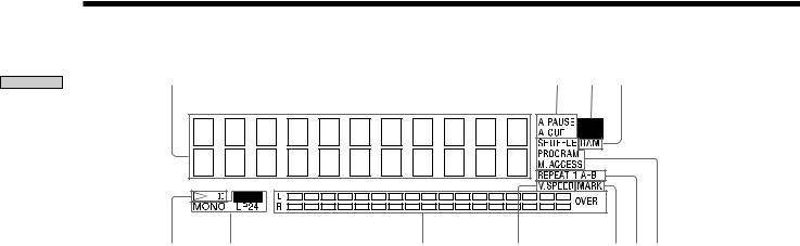
Display Window Discriptions
1
5 |
6 |
7 |
1Disc, track, and time display
Displays MD information, the set contents of “Edit Menu” or “Setup Menu,” and time information.
2AUTO PAUSE and AUTO CUE display
Lights up when AUTO PAUSE or AUTO CUE is selected.
3TOC EDIT display
Displays “TOC” when record contents or edit contents are not recorded on MD. Flashes “TOC” when they are recorded on MD.
“TOC” is displayed during edit operation.
4RAM display
Lights up in RAM edit mode in which temporary editing is performed for sending without recording editing results.
57 (play/pause) display
Displays during play or pause.
6Record and record mode display
REC display
Lights up during recording or pausing. Record mode display
Lights up “MONO” for monaural recording, “LP2” for double-length stereo recording, and “LP4” for 4-time length stereo recording in record mode or mode when the playing track is recorded.
2 3 4
89q;qa
7Level meter display
Displays the loudness of the sound of play or recording.
8VARI SPEED display
Lights up when the VARI SPEED function is selected.
9MARK display
Lights up when the position (MARK) of a located point is selected.
0REPEAT display
Displays “REPEAT” when all track repeat is selected, “REPEAT1” when one track repeat is selected, and “REPEAT A-B” when A-B repeat is selected.
!Á Play mode display
Displays “SHUFFLE” when shuffle play is selected, “PROGRAM” when program play is selected, and “M.ACCESS” when multi-access play is selected.
10
Using the Display Window
The display window shows information about the MD or track. This section describes the information that is displayed for each recorder status.
LEVEL / DISPLAY / CHAR |
TIME |
M.ACCESS |
|
|
|
|
TIME |
|
CONTINUE |
SHUFFLE PROGRAM |
|
|
|
DISPLAY |
1 |
2 |
3 |
4 |
5 |
|
|
|
6 |
7 |
8 |
9 |
10 |
|
|
11 |
12 |
13 |
14 |
15 |
|
|
16 |
17 |
18 |
19 |
20 |
|
|
21 |
22 |
23 |
24 |
25 |
|
|
>25 |
|
|
|
|
|
|
NAME |
CHAR |
NUM |
|
|
CD-SYNC
RM-DR1J 
n
The display format that you’ve selected in each of the recorder statuses (play, recording, etc.) will be displayed whenever the recorder enters that status and you press LEVEL/DISPLAY/CHAR (or DISPLAY) or TIME until you change the format to another (see the following sections for details).
When you insert an MD
Disk name
S O N G S 


 1 5 Tr
  4 6 m 0 8 s
|
|
|
Total number of tracks |
Total recorded time |
|
*The track name is displayed instead of the disc name during play. When the MD or the track has no name, “No Name” is displayed.
While the recorder is stopped
Press LEVEL/DISPLAY/CHAR (or DISPLAY) repeatedly to change the display.
Each press of the button changes the display as follows:
Total number of tracks and recorded time (default display)
S O N G S 


 1 5 Tr
  4 6 m 0 8 s
Press
The contents of a program
(only when “PROGRAM” lights up)
/ 4  1
1  7
7  5 /
5 / 


 4 S
4 S  1 2 m 3 5 s PROGRAM
|
|
|
|
|
|
|
|
|
|
|
|
|
|
|
|
Press |
|
|||||
|
Level of the input signal |
|
|
|
|
|
|
|
|
|
|
|
||||||||||
|
|
|
|
|
|
|
|
|
|
|
|
|
|
|
|
|
|
|
|
|
|
|
I |
|
n |
|
p |
|
u |
|
t |
|
|
|
L |
|
e |
|
v |
|
e |
|
l |
|
|
|
|
|
|
|
|
|
|
|
|
|
|
|
|
|
|
|
|
|
|
|
|
|
C |
|
o |
|
a |
|
x |
|
|
|
|
|
0 |
|
. |
|
0 |
|
d |
|
B |
|
|
|
|
|
|
|
|
|
|
|
|
|
|
|
|
|
|
Press |
|
|||||
|
Clock display (present time display) |
|
||||||||||||||||||||
|
|
|
|
|
|
|
|
|
|
|
|
|||||||||||
2 |
|
0 |
|
0 |
|
0 |
|
|
|
|
|
9 |
|
|
|
1 |
|
5 |
|
|
|
|
|
|
|
|
|
|
|
|
|
|
|
|
|
|
|
|
|
|
|
|
|
|
|
|
|
1 |
|
8 |
|
: |
|
0 |
|
8 |
|
|
|
4 |
|
4 |
|
|
|
|
|
Press |
zYou can check the remaining recordable time on the MD
Press TIME when the total number of tracks and recorded time are displayed. Each press of the button changes the display as follows:
Total number of tracks and total recorded time (default display)
S O N G S 


 1 5 Tr
  4 6 m 0 8 s
Press
Total number of tracks and remaining recordable time on the MD (recordable MDs only) *
S O N G S 


 - 2 7 m 5 2 s
Press
* Not shown for the premastered discs.
Parts of Function and Location
11

Parts of Function and Location
While the recorder is recording
Press LEVEL/DISPLAY/CHAR (or DISPLAY) repeatedly to change the display.
Each press of the button changes the display as follows:
Track number and recorded time of the current track (default display)
N o  N a m e


 1 6 Tr
 3 m 0 5 s
Press
Sampling frequency is indicated only when the digital signal is input.
F S  4 4 . 1 K H z
 1 6 Tr
 3 m 2 3 s
Press
Level of the input signal
I n p u t  L e v e l
C o a x - 1 2 . 0 d B
Press
zYou can check the remaining recordable time on the MD
Press TIME when the track number and recorded time are displayed. Each press of the button changes the display as follows:
Track number and recorded time of the current track (default display)
N o  N a m e


 1 6 Tr
 3 m 0 5 s
Press
Recordable time
N o  N a m e


 - 1 0 m 5 5 s
Press
While the recorder is playing
Press LEVEL/DISPLAY/CHAR (or DISPLAY) repeatedly to change the display.
Each press of the button changes the display as follows:
Track number and elapsed time of the current track (default display)
D R E A M 


 2 Tr
2 Tr 
 2 m 3 3 s
|
|
|
|
|
|
|
|
|
|
|
|
|
|
|
|
|
|
|
|
|
|
|
|
|
|
Press |
||||||||||
|
|
|
|
|
|
|
|
|
|
|
|
|
|
|
|
|
|
|
|
|
|
|
|
|
|
|||||||||||
The contents of a program |
|
|
|
|
|
|
|
|
|
|
|
|
|
|
|
|
|
|
|
|
|
|
|
|||||||||||||
(only when “ROGRAM” lights up) |
|
|
|
|
|
|
|
|
|
|
|
|
|
|||||||||||||||||||||||
|
|
|
|
|
|
|
|
|
|
|
|
|
|
|
|
|
|
|
|
|
|
|
|
|
||||||||||||
|
|
|
|
|
|
|
|
|
|
|
|
|
|
|
|
|
|
|
|
|
|
|
|
|
|
|
|
|
|
|
|
|
|
|
|
|
|
|
|
|
|
|
|
|
|
|
|
|
|
|
|
|
|
|
|
|
|
|
|
|
|
|
|
|
|
|
|
|
|
|
|
|
|
/ |
|
4 |
|
|
|
1 |
|
|
|
2 |
|
|
|
|
5 |
|
|
/ |
|
|
|
|
|
|
|
PROGRAM |
||||||||||
|
|
|
|
|
|
|
|
|
|
|
|
|
|
|
|
|
|
|
|
|
|
|
|
|||||||||||||
|
|
|
|
|
|
|
|
|
|
|
|
|
|
|
|
|
|
|
|
|
|
|
|
|
|
|
|
|
|
|
||||||
|
|
|
|
3 |
|
S |
|
|
|
|
|
|
|
2 |
|
m |
|
|
|
2 |
|
8 |
|
s |
||||||||||||
|
|
|
|
|
|
|
|
|
|
|
|
|
|
|
|
|
|
|
||||||||||||||||||
|
|
|
|
|
|
|
|
|
|
|
|
|
|
|
|
|
|
|
|
|
|
|
|
|
|
|
|
|
|
|
|
|
|
|
|
|
|
|
|
|
|
|
|
|
|
|
|
|
|
|
|
|
|
|
|
|
|
|
|
|
|
|
|
|
|
|
|
|
|
|
|
|
|
Press
*Only when “On” of “Next Tr Play” of “Setup Menu” is selected
N e x t N o  N a m e

 4 Tr
4 Tr 
 4 m 1 4 s
Press
Disc name and track name
S O N G S 


D R E A M 


Press
Level of the output signal
O u t p u t L e v e l
A n l g  - 6 . 0 d B
Press
*Not displayed if PLAY MODE is PROGRAM or SHUFFLE when “On” of “Next Tr Play” (Next Track Play) is selected.
12
zYou can check the remaining time
Press TIME. Each press of the button changes the display as follows:
Track number and elapsed time of the current track (default display)
D R E A M 


 2 Tr
2 Tr 
 2 m 3 3 s
Press
Track number and remaining time of the current track
D R E A M 


 2 Tr
2 Tr  - 1 m 2 5 s
Press
Remaining time of all recorded tracks
D R E A M 


 - 2 4 m 4 7 s
Press
zPress SCROLL when disc time information is displayed
The track name appears and scrolls. While the track name is scrolling, press the button again to pause scrolling, and again to continue scrolling.
Parts of Function and Location
13
Getting Started After Unpacking
Check the supplied accessories.
• Remote commander (remote) RM-DR1E (1)
• AA-size (R6) batteries (2)
• Connecting cable (control S cable) (1)
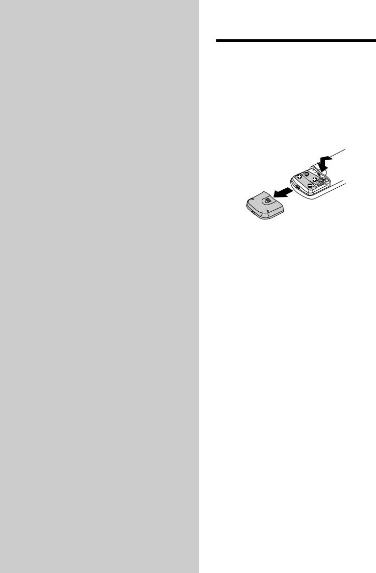
Inserting batteries into the remote
Insert two AA-size (R6) batteries with the 3 and # properly oriented to the markings into the battery compartment.
z When to replace the batteries
Under normal conditions, the batteries should last for about six months. When the remote no longer operates the recorder, replace both batteries with new ones.
Notes
• If you use the batteries incorrectly, they may leak liquid or be blown up. Be sure to obey the following points: - Do not mistake 3 and # terminals.
- Do not use a new battery with an old one or batteries of different types together.
- Do not recharge the batteries.
- If you don’t use the remote for an extended period of time, remove the batteries.
- If the batteries are leaking, wipe to clean the battery compartment before replacing with new ones.
• Do not expose the remote sensor to direct sunlight or lighting apparatus. Doing so may cause a malfunction.
14
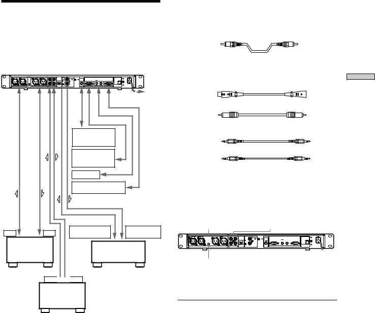
Hooking Up the Audio
Components
Hook up a mixer, CD player, DAT recorder, and other components to the MD recorder. Be sure to turn off the power of each component to do so.
R |
IN |
L |
R OUT |
L |
|
|
ANALOG |
DIGITAL |
CTRL-S |
|
|
|
|
|
|
|
|
|
L |
INPUT |
IN |
|
|
|
|
|
|
OUTPUT |
|
|
|
LEVEL |
|
PARALLEL |
RELAY |
|
RS-232C |
|
|
|
LEVEL |
|
IN |
OUT |
5 |
|
IN |
OUT |
IN |
230V |
|
|
|
+4dBu |
-10dBu |
|
|
|
|
|
|
|
|
120V |
|
|
|
|
|
|
R |
|
OUT |
|
|
|
|
|
|
|
|
|
|
|
0 10 |
COAXIAL |
|
REMOTE |
VOLTAGE |
|
|
|
ANALOG(BAL) |
|
ANALOG(UNBAL) |
|
|
SELECTOR |
|||||
|
|
|
|
|
|
|
|
|
|
|
|
To power outlet |
|
|
|
|
|
|
|
|
Remote or |
|
|
||
|
|
|
|
|
|
|
|
control |
|
|
|
|
|
|
|
|
|
|
|
|
component |
|
|
||
|
|
|
|
|
|
|
|
External |
|
|
|
|
|
|
|
|
|
|
|
|
control |
|
|
|
|
|
|
|
|
|
|
|
|
component |
|
|
||
|
|
|
|
|
|
|
|
MDS-E12 |
|
|
|
|
|
|
|
|
|
|
|
|
External |
|
|
|
|
|
|
|
|
|
|
|
|
control component |
||||
OUT |
IN |
DIGITAL |
DIGITAL |
|
COAXILAL OUT |
COAXILAL IN |
|||
|
|
|||
Mixer |
|
CD player or |
|
|
|
DAT recorder, |
|
||
|
|
MD recorder |
|
OUT

 IN
IN
Mixer
•: Flow of signal
zWhen the remote is used as the wired remote
Use the supplied control S cable to connect the jack at the front of the remote with the control jack of the recorder.
When the recorder and remote are connected by the control S cable, infrared rays are not emitted from the remote and infrared rays are not received by the recorder.
When the remote is used as the wireless remote, unplug from the jacks of the recorder and remote.
1Prepare necessary connecting cables.
• Audio connecting cable (pin type)
White |
White |
Left (L) |
Left (L) |
Right (R)
 Right (R)
Red |
Red |
•Audio connecting cable (XLR type)
•Coaxial digital connecting cable VMC-10
•Control-S cable (accessory)
(Mini-jack)
• Relay record/play cable (RK-G136)
(Stereo-Mini-jack type) (Stereo-Mini-jack type)
2 Connect.
xWhen connecting with analog components
Use the connectors and switch in the figure below.
ANALOG BLANCE |
ANALOG UNBLANCE |
I/O terminal |
I/O terminal |
R |
IN |
L |
R |
OUT |
L |
|
|
ANALOG |
DIGITAL |
CTRL-S |
|
|
|
|
|
|
|
|
|
|
|
L |
INPUT |
IN |
|
|
|
|
|
|
|
OUTPUT |
|
|
|
|
LEVEL |
|
PARALLEL |
|
RELAY |
RS-232C |
||
|
|
LEVEL |
|
|
IN |
OUT |
|
5 |
|
IN |
OUT |
IN |
230V |
|
|
|
+4dBu |
-10dBu |
|
|
|
|
|
|
|
|
|
|
120V |
|
|
|
|
|
|
|
R |
|
|
OUT |
|
|
|
|
|
|
|
|
|
|
|
|
0 |
10 |
COAXIAL |
|
|
|
VOLTAGE |
|
|
ANALOG(BAL) |
|
|
ANALOG(UNBAL) |
|
|
|
REMOTE |
SELECTOR |
||||
OUTPUT LEVEL selector
Change the INPUT selector on the front panel depending on the type of the input connector to be used.
Connector to which the |
Position to adjust the INPUT |
program source is |
selector |
connected |
|
|
|
UNBAL IN |
UNBAL |
(pin type) |
|
|
|
BAL IN |
BAL |
(XLR type) |
|
|
|
zA signal is output to both the UNBAL and BAL output terminals regardless of the setting of the INPUT switch
zWhen the BALANC output (XLR type) terminals is used, the output level can be changed by the OUTPUT LEVEL selector
Started Getting
15

Started Getting
Position of selector |
Output level |
|
+4dBu |
A signal of –20 dB at the level meter |
|
|
is output at the level of +4 dBu. |
|
–10dBU |
A signal of –20 dB at the level meter |
|
|
is output at the level of –10 dBu. |
|
The specifications of the BALANCE I/O connector are |
||
shown below. |
|
|
Input terminal |
|
Output terminal |
XLR-3-31 equivalent |
XLR-3-32 equivalent |
|
1: GND |
|
1: GND |
2: HOT |
|
2: HOT |
3: COLD |
3: COLD |
|
xWhen connecting with digital components (CD player, DAT recorder, other MD recorders, mixer with a coaxial digital input connector)
When this recorder is connected with a CD player, MD recorder, or DAT recorder, digital recording is possible. Use a coaxial digital connecting cable that can be purchased separately.
When the coaxial digital cable is used
MD recorder |
Digital component |
DIGITAL |
DIGITAL |
|
IN |
COAXIAL |
|
|
|
|
|
IN |
OUT |
OUT |
|
|
COAXIAL |
|
|
|
‚ |
|
|
‚ |
|
•: Flow of signal
zA sampling rate converter is mounted in this recorder
All digital input signals are converted to the sampling frequency (44.1 kHz) of an MD recorder for recording.
Therefore, this allows you to record sources such as 32 or 48 kHz DAT or satellite broadcasts, as well as CDs and MDs.
3 Connect the power cord.
16
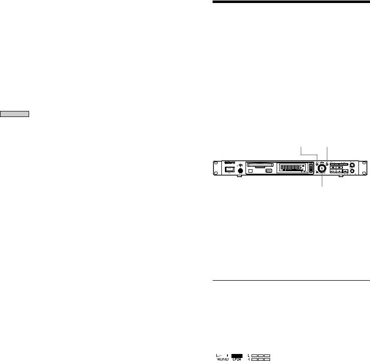
Setting the Clock
A clock is built in this recorder. The recording time is recorded automatically on the disc to set the clock in advance. You can check the recording time during play.
MENU / NO YES
AMS  /
/ 
1Press the Menu/NO button twice during stop.
“Setup Menu” is displayed.
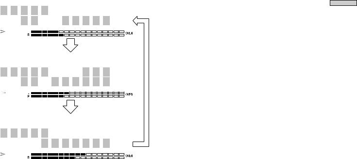
2Turn AMS (or press ./> repeatedly) to display “Calendar” and press AMS.
The portion of “Year” flashes.
2 0 0 0 - |
7 |
- |
1 |
2 |
|
1 |
9 |
: |
0 0 |
3Turn AMS (or press ./> repeatedly) to set the “Year” and press AMS.
The portion of “Year” lights up and the portion of “Month” flashes.
2 0 0 0 -  7 - 1 2


 1 9 : 0 0
4Similarly with step 3, set “Month,” “Day,” “Hour,” and “Minute” in this order.
After “Complete !” is displayed for several seconds and disappears, the clock starts to work.
Resetting the clock
1Do steps 1 to 2 of “Setting the Clock” on this page.
2Press AMS or m/M repeatedly to flash the portion to be changed.
3Turn AMS (or press ./> repeatedly) for setting and press AMS.
4After setting, press AMS or m/M repeatedly to flash the portion of “Minute” and press AMS or YES.
Watching the clock Z
When the power is on, you can watch the clock.
Press DATE PRESENT.
When DATE PRESENT is pressed once, the date and time are displayed for about 2 seconds and they are returned to the original display.
•If you want to record more precise recording time, set the clock once a week.
Checking the recording time Z
If the built-in clock is set, the recording time is recorded on the MD. You can check the recording time at the display window during play.
1Select a track for which you want to check the recording time.
Select a track by ./> during stop.
Select a track by ./> or Number during play or pause of play.
2Press DATE RECORDED.
“No Date” is displayed if the clock is not set or for the track recorded by a component without a function of recording the recording time.
Selecting the order of year, month, and
day of clock display
You can select the order of the year, month, and day of clock display from the following three ways:
1Press MENU/NO twice during stop.
“Setup Menu” is displayed.
2Turn AMS (or press ./> repeatedly) to display “Date Time” and press AMS or YES.
3Turn AMS (or press ./> repeatedly) to select the order of the year, month, and day and press AMS or YES.
Order of year, month, and day
D a t e  T i m e

Y Y Y Y  M M
M M  D D
D D 
Order of month, day, and year
D a t e  T i m e

M M  D D
D D  Y Y Y Y
Order of day, month, and year
D a t e  T i m e

D D  M M
M M  Y Y Y Y
4 Press MENU/NO.
Started Getting
17

Recording on MDs
This chapter explains the various ways to record to an MD , as well as how to mark track numbers and perform synchrorecording with other components.
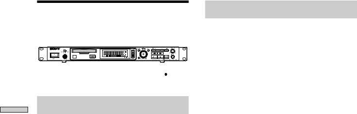
Recording on an MD
If the MD has recorded material on it, the recorder will automatically start recording from the end of the recorded portion.
POWER INPUT |
LEVEL / DISPLAY / CHAR |
TIME |
||||||||||||
|
|
|
|
|
|
|
|
|
|
|
|
|
|
|
|
|
|
|
|
|
|
|
|
|
|
|
|
|
|
|
|
|
|
|
|
|
|
|
|
|
|
|
|
|
|
|
|
|
|
|
|
|
|
|
|
|
|
|
|
|
|
|
|
|
|
|
|
|
|
|
|
|
|
|
|
|
|
|
|
|
|
|
|
|
|
|
|
|
|
|
|
|
|
|
|
|
|
|
|
|
|
|
|
|
|
|
|
|
|
|
|
|
|
|
|
|
|
|
|
|
|
|
|
|
|
|
|
|
|
|
|
|
|
|
AMS
1Turn on the mixer and program source.
2Select the source on the mixer.
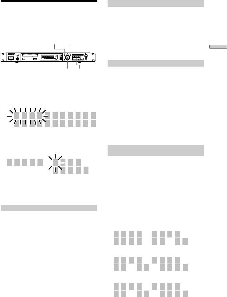
3Press POWER to turn on the recorder.
4Insert a recordable MD.
5Use INPUT to select the position that corresponds to the input jacks (connector) connected to the program source.
If the source is connected |
Display to be selected |
to the connector or jacks |
|
|
|
DIGITAL COAXIAL |
COAX |
ANALOG (UNBAL) |
UNBAL |
ANALOG (BAL) |
BAL |
6If necessary, locate the point on the MD to start recording from.
If you want to record on a new MD or start recording from the end of the recorded portion, go to step 7.
•To record over from the beginning of an existing MD track
Turn AMS (or press ./> repeatedly) until the number of the track to be recorded over appears.
•To record over from the middle of an MD track
Turn AMS (or press ./> repeatedly) until the number of the track to be recorded over appears, then press 7 to start playback. Press 7 again at the point you want to start recording from.
7Press z
The recorder changes to recording pause.
8If necessary, adjust the recording level.
For details, see “Adjusting the Recording Level” on page 21.
9Press 7
Recording starts.
10Start playing the program source.
18
Operations you may want to do during recording
To |
Press |
Stop recording |
x |
Pause recording |
7 |
Resume recording after |
7 |
Eject the MD |
after stopping recording A |
Changing display during recording
Press LEVEL/DISPLAY/CHAR (DISPLAY) repeatedly. For the contents of display, see “Using the Display Window” on page 12.
When you pause recording
The track number increases by one. For example, if you pause recording while recording track 4, the track number will be 5 when you resume recording.
To prevent accidental erasure of the recorded material
To make it impossible to record on an MD, slide the record-protect tab in the direction of the arrow (see illustration below) to open the slot. To enable recording, close the slot.
Record-protect tab
Slide in the direction of arrow
zYou can play the tracks you have just recorded
Press 7 or AMS immediately after stopping recording.
The recorder starts to play from the first track of the material just recorded.
zYou can play from the first track of the MD after recording
1 Press x again after stopping recording.
2 Press 7
The recorder starts to play from the first track of the MD.
Notes
•You can’t record over existing material when Shuffle Play (page 32), Program Play (page 33), or Multi-access Play (page 34) has been selected. “Impossible” appears in the display at this time.
Notes on Recording
When “ Protected” is displayed
The MD is record-protected. To record on the MD, slide the tab to close the slot (see “To prevent accidental erasure of the recorded material” on page 19).
When the record-protect slot is closed and recording is possible, “Protected” may be displayed and recording may not be possible. In this case, press z (record) again to enable recording.
When “Din Unlock” flashes
•The digital component selected with the INPUT selector is not connected correctly. Connect the component correctly.
•The selected digital component is not turned on. Turn on the component.
Marking track numbers depends on the program source to be recorded.
•When the CD or MD is a program source and they are recorded through the digital input connector, track numbers are marked similarly with the CD or MD as the program source. However, only one track number may be marked on the recorded portion as below.
-A portion recorded by repeating the same track of the same disc (by one track repeat)
-A portion recorded by continuing the same track number of a different disc
When the MD is the program source, a number for a track of 4 seconds or less may not be marked.
•If the sampling frequency of the input connector changes when the DAT tape is a program source and it is recorded through the digital input connector, track numbers are changed automatically.
When TOC indicator flashes
Do not turn off the recorder, disconnect the AC power, or move the recorder when recording on the MD because the recording will be lost. If you turn off the recorder or disconnect the AC power immediately after recording, the recording will be lost.
When PLAY MODE is “PROGRAM,” “SHUFFLE,” or “M.ACCESS” (pages 32, 33, 34)
PLAY MODE changes automatically to “CONTINUE” and recording pauses.
When ”Cannot Copy” flashes
The mini-disc recorder conforms to the Serial Copy Management System. MDs recorded through the digital input connector cannot be copied to other MDs through the digital output connector (page 65).
MDs on Recording
19
MDs on Recording
The digital output connectors of the mini-disk recorder output the signal input from the digital input connectors as it is during recording or recording pause.
Use an input monitor function (page 22) when only a builtin sampling rate converter is used.
Recording for long times
In addition to normal stereo recording, this recorder has two long time recording modes: LP2 and LP4. When recording in LP2 stereo mode, you can record 2 times the normal recordable time, and in LP4 Stereo mode, you can record 4 times the normal recordable time. In addition, the recordable time for monaural recording is approximately double the stereo recording time.
Note
MDs recorded in MD LP (LP2 or LP4 Stereo) mode cannot be played back on a recorder that does not support MD LP mode. In addition, you cannot perform S.F Edit for MDs recorded in MD LP mode.
MENU / NO YES
AMS
1Do steps 1 to 5 of “Recording on an MD” on page 18.
2Press MENU/NO twice.
“Set Up Menu” is displayed.
3Turn AMS (or press ./> repeatedly) to display “Rec Mode” and press AMS.
4Turn AMS to select record mode and press AMS or YES.
To record in |
|
|
|
|
Display to be selected |
|||||||
Stereo |
|
|
|
|
Stereo |
|||||||
Monaural |
|
|
|
|
Mono |
|||||||
LP2 stereo |
|
|
|
|
Long 2 |
|||||||
LP4 stereo |
|
|
|
|
Long 4 |
|||||||
|
|
|
|
|
|
|
|
|
|
|
|
“LP2,” “LP4,” or “MONO” lights |
|
|
|
|
|
|
|
|
|
|
|
|
|
|
|
|
|
|
|
|
|
|
|
|
|
up on the lower left of the display |
|
|
|
|
|
|
|
|
|
|
|||
|
|
|
|
|
|
|
|
|
|
|
|
window by the selected mode. |
|
|
|
|
|
|
|
|
|
|
|||
|
|
|
|
|
|
|
|
|
|
|
|
|
|
|
|
|
|
|
|
|
|
|
|
|
|
5Press MENU/NO.
6Do steps 6 to 10 of “Recording on an MD” on page 18.
Hidden “LP:” is recorded at the beginning of tracks during MD LP recording.
This is a confirmation stamp indicating no play when play is performed by the non-MD LP component. The stamp is not displayed by playable MD LP components, but is displayed when play is performed by the non-MD LP component.
If the name of the MD LP-recorded track is copied as the name of the MONO or STEREO recorded track, “LP:” is displayed (page 48).
20
Adjusting the Recording
Level
You can adjust the recording level for both analog and digital recording.
MENU / NO YES LEVEL / DISPLAY / CHAR
AMS
1Do steps 1 to 7 of “Recording on an MD” on page 18.
2Play the portion of the program source with the strongest output.
3Press LEVEL/DISPLAY/CHR (or DISPLAY) repeatedly until the level of the input signal appears.
4Turn AMS (or press LEVEL +/_repeatedly) to adjust the recording level.
Adjust the recording level so that two rightmost indicators on the peak level meters do not light up when the play level is the highest level.
I n p u t  L e v e l
C o a x  - 5 . 0 d B
Avoid turning on these indicators
5Stop playing the program source.
6To start recording, continue from step 9 of “Recording on an MD” on page 18.
zYou can adjust the recording level using the remote Z
During recording or recording pause, press LEVEL +/- repeatedly.
zYou can use Setup Menu to adjust the recording level
1During recording or recording pause, press MENU/NO twice.
“Setup Menu” appears in the display.
2Turn AMS (or press ./> repeatedly) to select “Input Level Coax,” “Input Level BAL,” or “Input Level UNBL,” then press AMS or YES.
3Turn AMS (or press ./> repeatedly) to adjust the recording level, then press AMS or YES.
4Press MENU/NO.
zThe balance of the left and right recording levels can be adjusted in Setup Menu during analog input
1Press MENU/NO twice.
“Setup Menu” appears in the display.
2Turn AMS (or press ./> repeatedly) to select “BAL In L/R” or “UNBAL In L/R” then press AMS or YES.
3Turn AMS (or press ./>) to adjust the balance. When you turn AMS clockwise, the level on the L side decreases relatively for R. When you turn it counterclockwise, the level on the R side decreases for L. Press AMS or YES.
4Press MENU/NO.
zTurn ANALOG INPUT LEVEL at the rear of the recorder to adjust the recording level of analog input.
R |
IN |
L |
R |
OUT |
L |
|
|
ANALOG |
DIGITAL |
CTRL-S |
|
|
|
|
|
|
|
|
|
|
L |
INPUT |
IN |
|
|
|
|
|
|
OUTPUT |
|
|
|
|
LEVEL |
|
PARALLEL |
RELAY |
RS-232C |
||
|
|
LEVEL |
|
|
IN |
OUT |
|
5 |
|
IN |
OUT |
IN |
|
|
|
+4dBu |
-10dBu |
|
|
|
|
|
|
|
|
|
|
|
|
|
|
|
|
|
R |
|
|
OUT |
|
|
|
|
|
ANALOG(BAL) |
|
|
ANALOG(UNBAL) |
0 |
10 |
COAXIAL |
|
REMOTE |
|||
|
|
|
|
|
|
|
|||||||
ANALOG INPUT LEVEL
A range of _∞ ~ +15 dB can be adjusted by ANALOG INPUT LEVEL. This adjustment can be used when the analog output level of connected components is too low or too high.
Normally use the range in the initialized center position (0dB).
z You can use a peak hold function
The state of the peak level meter when the level of the input/output signal is the highest can be stopped for display until the signal exceeding the level is input.
1Press MENU/NO twice during stop or play.
2Turn AMS (or press ./> repeatedly) until “Peak Hold” appears, then press AMS or YES.
3Turn AMS (or press ./> repeatedly) to select “On,” then press AMS or YES.
4Press MENU/NO.
To cancel the peak hold function, select “Off” at step 3.
Note
The volume can only be increased up to +12 dB (for analog recording) or +18.0 dB (for digital recording). Therefore, if the output level of the connected component is low, it may not be possible to set the recording level to maximum.
MDs on Recording
21
MDs on Recording
Recording Tips
INPUT |
MENU / NO |
YES |
||||||||
|
|
|
|
|
|
|
|
|
|
|
|
|
|
|
|
|
|
|
|
|
|
|
|
|
|
|
|
|
|
|
|
|
|
|
|
|
|
|
|
|
|
|
|
|
|
|
|
|
|
|
|
|
|
|
|
|
|
|
|
|
|
|
|
|
|
Z EJECT |
AMS |
Monitoring the input signal (Input
Monitor)
You can monitor the selected input signal even when you aren’t recording it.
1Press Z to eject the MD.
2Use INPUT to select the program source to be monitored.
3Press z.
•When “UNBAL” or “BAL” is selected by INPUT
The analog signal input from the ANALOG IN jacks is output to the COAXIAL OUT connector after A/D conversion, and then to the ANALOG OUT jacks and PHONES jack after D/A conversion.
“AD - DA” appears in the display during this time.
•When “COAXIAL” is selected by INPUT
The digital signal input from the DIGITAL IN connector is output to the DIGITAL OUT connector after passing through the sampling rate converter, and then to the ANALOG OUT jacks and PHONES jack after D/A conversion.
“- DA” appears in the display during this time.
Stopping the input monitor
Press x.
Erasing blank portions automatically
(Smart Space/Auto Cut)
The recorder can be set to automatically erase any blanks that are produced when the signal is interrupted during recording. The function which activates (Smart Space or Auto Cut) depends on the length of the interruption, as described below.
Smart Space
If the signal is interrupted for less than 30 seconds, Smart Space replaces the blank portion with a blank space of about 3 seconds, then continues the recording. “Smart Space” appears in the display during this time.
Auto Cut
If the signal is interrupted for about 30 seconds, Auto Cut replaces the blank portion with a blank space of about 3 seconds, then pauses the recording. “Auto Cut” appears in the display during this time.
Do the procedure below to turn Smart Space and Auto Cut on or off.
1While the recorder is stopped, press MENU/NO twice.
“Setup Menu” appears in the display.
2Turn AMS (or press ./> repeatedly) until “Smart Space” appears, then press AMS or YES.
3Turn AMS (or press ./> repeatedly) and select “On” for automatic operation and “Off” for no automatic operation, then press AMS or YES.
4Press MENU/NO.
Note
•If you start recording with no signal input, Smart Space and Auto Cut will not operate until the signal is input regardless of the setting.
•Smart Space does not affect the order of the track numbers being recorded, even if the blank space occurs in the middle of a track.
•Auto Cut is automatically turned on or off in tandem with Smart Space.
•If you turn off the recorder or disconnect the AC power cord, the recorder will store the last setting and recall it the next time you turn on the recorder.
22
 Loading...