


MDR-RF875R

MDR-RF875R
SERVICE MANUAL
Ver 1.0 2000. 08
MDR-RF875R is the component model block one in the MDR-RF875RK.
COMPONENT MODEL NAME FOR MDR-RF875RK
Headphones MDR-RF875R
Transmitter TMR-RF875R
AEP Model
UK Model
SPECIFICATIONS
Headphones
Power source DC 2.4 V: Built-in rechargeable
battery
Mass Approx. 350 g (12.25 oz.) incl.
built-in rechargeable battery
Built-in Ni-MH rechargeable battery
Model name NH-AAC
Voltage 1.2 V
Capacity 1,000 mAh
Design and specifications are subject to change without
notice.
HEADPHONES
SECTION 1
GENERAL
This section is extracted
from instruction manual.
5
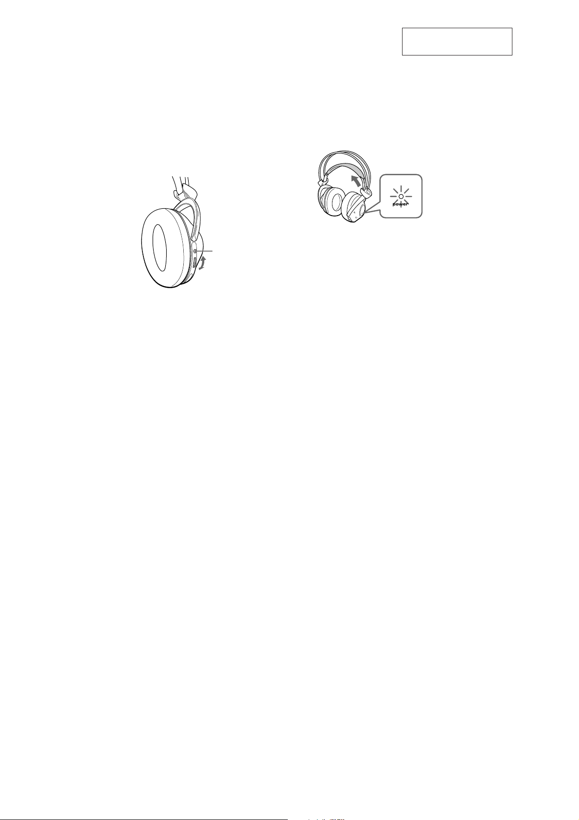
Turn up the volume to a moderate
level with the VOL control.
Press the TUNING button briefly for
automatic tuning of the headphones.
If you do not receive a clear audio
signal, press it again.
TUNING
VOL control
Try the above steps 3 and 5 until the
receiving performance becomes better.
Auto power on/off function
When you remove the headphones from your
head, the power turns off automatically. Do not
allow the self adjusting band to be pulled up,
otherwise the headphones will be switched on.
The power turns on.
Note
If a hissing noise is heard move closer to the transmitter.
Flexible Circuit Board Repairing
• Keep the temperature of soldering iron around 270˚C
during repairing.
• Do not touch the soldering iron on the same conductor of the
circuit board (within 3 times).
• Be careful not to apply force on the conductor when soldering
or unsoldering.
Notes on chip component replacement
• Never reuse a disconnected chip component.
• Notice that the minus side of a tantalum capacitor may be
damaged by heat.
— 2 —
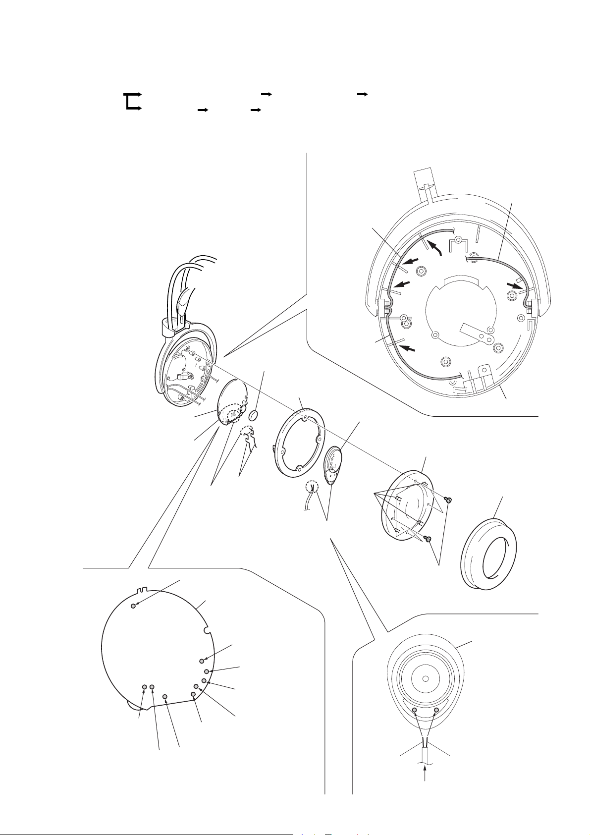
SECTION 2
DISASSEMBLY
• The equipment can be removed using the following procedure.
Set
Driver (R side), RX-BASE board
Driver (L side), Hanger (L)
SW board, Harger (R)
Holder (L)
Note : Follow the disassembly procedure in the numerical order given.
2-1. DRIVER (R SIDE), RX-BASE BOARD
9
Volume knob
Set the each leads as illustrated below.
From head
band assy (rear).
Holder (R)
From head
band assy (front).
Groove
Groove
Groove
From
SW board.
Groove
qa
RX-BASE board
0
Remove the
eight solderings.
(Housing (R) side)
Head band
assy (front)(natural)
8
Charge terminal
7
Remove the
two solderings.
Precaution for installtion
ANT
RX-BASE board
SW board
Head band
assy (rear)(natural)
Head band
assy (rear)(green)
Driver (natural)
Driver (red)
4
Ear pad holder (R)
5
Remove the
two solderings.
6
Four
claws
Driver
2
Four screws (M 2
Housing (R)
Precaution for installtion
3
Front plate (R) assy
1
Ear pad
× 5)
Precaution for installtion
Driver (R side)
Head band
assy (front)(black)
Solder the each leads directly to the position as shown
while being cautions of colors.
SW board
Red Natural
From RX-BASE board.
— 3 —

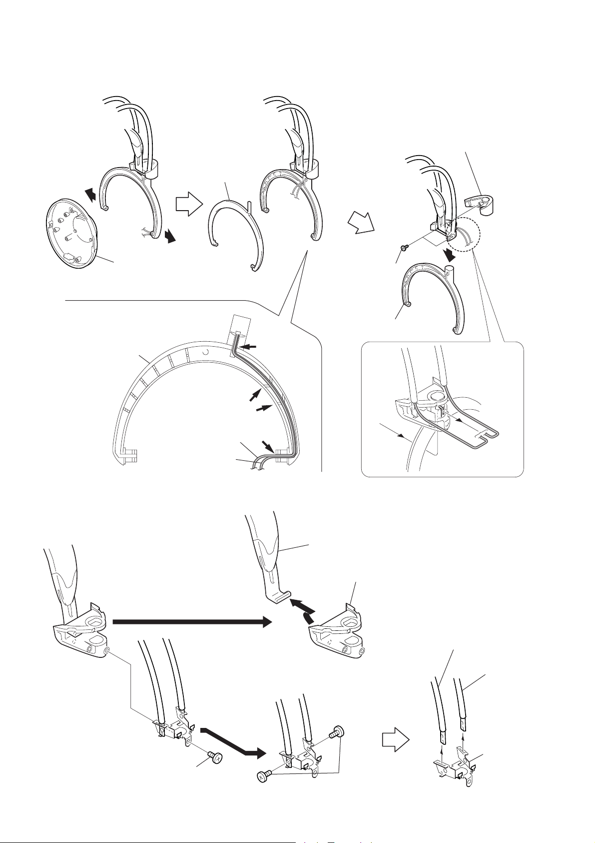
2-2. SW BOARD, HANGER (R)
s
1
1
2
Housing (R)
Precaution for installtion
Set the each leads as illustrated below.
From
SW board.
Groove
Hanger (R)
3
Hanger lid (R)
8
7
Remove the
two solderings.
SW board
5
Holder lid (R)
4
Two screw
(P 2
9
Hanger (R)
× 8)
Groove
2-3. HOLDER (R)
Groove
From head
band assy (front).
From head
band assy (rear).
2
Spring
Groove
Groove
Groove
3
Holder (R)
SW board
6
4
Head cushion assy
8
Head band assy (front)
7
Head band assy (rear)
1
Screw (P 2
× 8)
— 4 —
5
Two screws
(P 2
× 8)
6
Shassis

2-4. DRIVER (L SIDE)
Set the each leads as illustrated below.
From head
band assy (front).
Groove
Groove
Housing (L)
Precaution for installtion
3
Front plate (L) assy
1
Ear pad
2
Four screws (M 2
Precaution for installtion
× 5)
Driver (L side)
From head
band assy (rear).
8
Driver
Four
claws
7
Remove the
two solderings.
4
Two nickle
hydrogen batterys
6
Ear pad
holder (L)
Green
Natural
5
Remove the
two solderings.
Green Natural
From head band assy (rear).
— 5 —
2-5. HANGER (L)
1
3
Hanger lid (L)
1
2
Housing (L)
Precaution for installtion
4
Two screws
× 5)
(M 2
5
Holder lid (L)
Set the each leads as illustrated below.
2-6. HOLDER (L)
Hanger (L)
Groove
From head
band assy (front).
From head
band assy (rear).
Groove
Groove
7
Hanger (L)
3
Head cushion assy
2
Holder (L)
6
6
Head band assy (front)
7
Head band
assy (rear)
5
Shassis
1
Screw (M 2
× 5)
4
Two screws
(M 1.7
× 3)
— 6 —
SECTION 3
4
4
+
–
Digital voltmeter
(AC range)
IC301 pin6
+
–+–
IC301 pin6
IC301 pin4
OSCILLOSCPE
CH1 CH2
7
7
ELECTRICAL ADJUSTMENTS
Notes:
1. Use a transmitter to which check and adjustment are already
completed.
2.
On adjusting the headphones section, use the transmitter as a jig.
Headphones:MDR-RF875R
Transmitter:TMR-RF875R
Procedure:
1. Connect an oscillator with attenuator and terminator (600 Ω)
to the transmitter AUDIO IN-A connector (J402).
2. Connect an A C adapter to the transmitter DC IN 9V jack (J404).
3. Short between Q303 collector and GND on the RX board.
4. Connect DC 2.4V to the +B power line externally.
5. Connect lead wires to IC301 pin 4, pin 6, pin 7, IC 307 pin 7,
IC 308 pin 7 and GND on the RX-BASE board.
6. Connect a 33KΩ resistor between IC301 pin 4 and pin 7.
7. Connect lead wires to the speakers’ terminals (L+,L-,R+,R-)
on the RX-BASE board. (See page 9)
3-1. Free Run Frequency Check and Adjustment
1. Set the transmitter AUDIO IN-A connector (J402) to no signal.
Note: In this case, operation time is about 4 or 5 minutes.
2. Check the transmitter power indicator (red) lights.
3. Set the transmitter CHANNEL switch to 1.
4. Connect DC 1.2V across TP and GND.
5. Connect a frequency counter to IC301 pin 4 and GND on the
RX-BASE board.
6. Adjust the value of the frequency counter to specification by
RV301 on the RX-BASE board.
Specified values: 76kHz ± 50Hz.
Setting :
Requlated power supply
(DC 1.2V)
TP
+
–
Frequency counter
+
–
IC301 pin
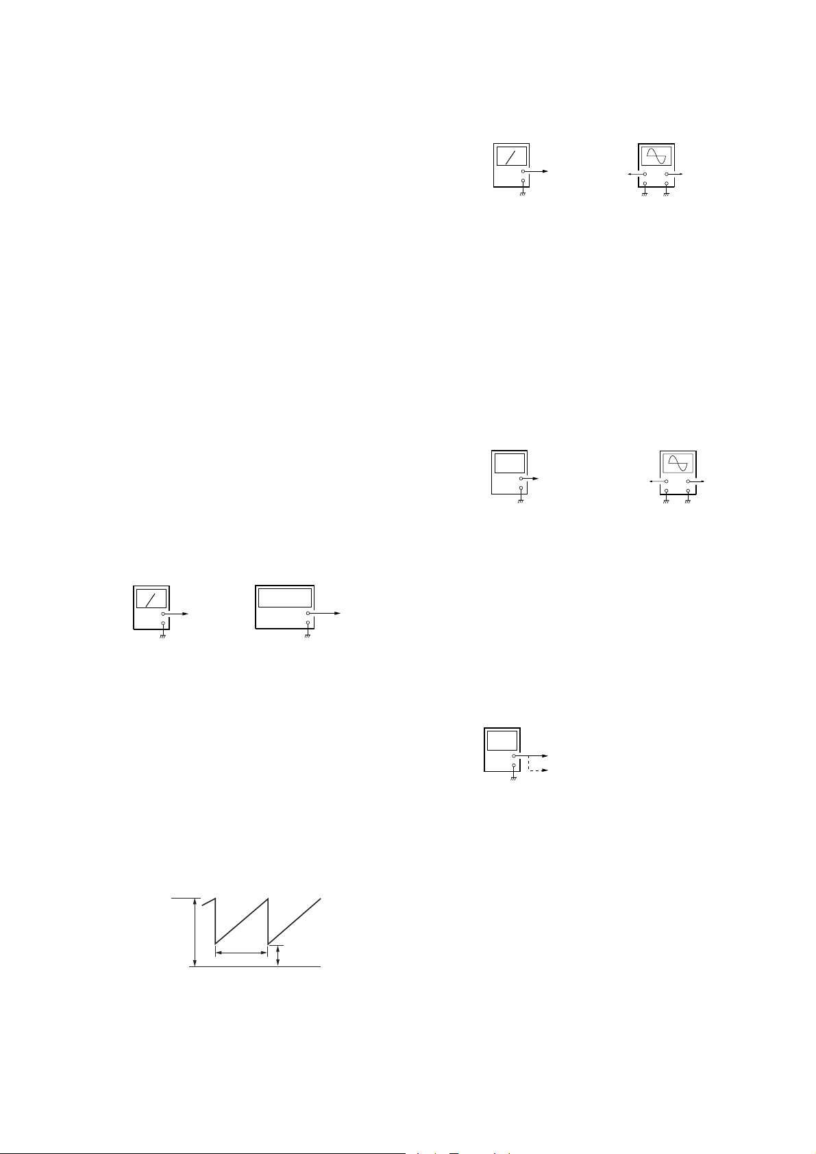
3-2. Receive Frequency Check and Adjustment
1. Set the transmitter CHANNEL switch to 2.
2. Set the transmitter NOISE FILTER switch to OFF.
3. Input a signal of 1kHz, 316mVrms to transmitter AUDIO INA (L-ch) connector only.
4. Keep distance between transmitter and headphones to 5 meters over.
5. Set the headphones volume (RV302) to minimum.
6. Connect DC 1.2V across TP and GND.
7.
Connect an oscilloscope CH1 and CH2 to IC301 pin 6 and pin 4.
8. Check the waveform of the oscilloscope to CH1 is demodulated
1kHz signal and CH2 is GND.
9. If CH1 and CH2 are not satisfied in step 8, adjust the coil (L301)
on the RX board to satisfied step 8.
10. Open between Q303 corrector and GND on the RX board.
11. When the transmitter off, check the waveform of the
oscilloscope as follows:
1.8V
GND
2–3 sec
12. Set the transmitter CHANNEL switch to 1.
13. Push the headphones tuning switch (S301) to receive radio
frequency.
14. Check same step 8.
15. Set the transmitter CHANNEL switch to 3.
16. Push the headphones tuning switch (S301) to receive radio
frequency.
17. Check same step 8.
0.6V
Setting :
Requlated power supply
(DC 1.2V)
TP
+
–
OSCILLOSCPE
IC301 pin6
CH1 CH2
+
–+–
IC301 pin
3-3. Carrier Modulation Check
1. Set the transmitter CHANNEL switch to 2.
2. Set the transmitter NOISE FILTER switch to OFF.
3. Input a signal of 1kHz, 316mVrms to transmitter AUDIO INA (L-ch) connector only.
4. Set the headphones volume (RV302) to minimum.
5.
Connect an oscilloscope CH1 and CH2 to IC301 pin 6 and pin 4.
6. Push the headphones tuning switch (S301) to receive radio
frequency.
7. Check the waveform of the oscilloscope that the CH1 is
demodulated 1kHz signal and CH2 is GND.
8. Connect an AC voltmeter with LPF to IC301 pin 6 and GND.
9. Check the value of the AC voltmeter to 40mVrms ± 5mV
Setting :
3-4. Expander Output Check
1. Set the transmitter CHANNEL switch to 2.
2. Input a signal of 1kHz, 316mVrms to transmitter AUDIO INA L and R connector.
3. Connect an AC voltmeter to IC307 pin 7 and IC308 pin 7.
4. Measure the value of the AC voltmeter.
5. Input a signal of 1kHz, 31.6mVrms to transmitter AUDIO INA L and R connector.
6. Measure the value of the AC voltmeter.
7. Check the difference of the step 4 and step 6 to more than 20
dB ± 3 dB.
Setting :
Digital voltmeter
(AC range)
+
–
IC307 pin
IC308 pin
3-5. Separation Check
1. Set the transmitter CHANNEL switch to 2.
2. Set the transmitter NOISE FILTER switch to OFF.
3. Input a signal of 1kHz, 316mVrms to transmitter AUDIO INA (L-ch) connector only.
4. Connect an oscilloscope CH1 to speakers terminal (L+,L-) and
CH2 to IC301 pin 4 and GND.
5. Push the headphones tuning switch (S301) to receive radio
frequency.
6. Check the waveform of the oscilloscope that the CH1 is
demodulated 1kHz signal and CH2 is GND.
7.
Connect an AC voltmeter with LPF to speakers terminal (L+,L-).
8. Adjust the value of the AC voltmeter to specification by
headphones volume RV302.
Specified values: 155mVrms
9.
Connect an A C v oltmeter with LPF to speak ers terminal (R+,R-).
10. Measure the value of the AC voltmeter.
11. Check the difference of the L and R to more than 25dB.
12. Input a signal of 1kHz, 316mVrms to transmitter AUDIO INA (R-ch) connector only.
— 7 —

13.
4
4
Connect an A C v oltmeter with LPF to speak ers terminal (R+,R-).
14. Adjust the value of the AC voltmeter to specification by
headphones volume RV302.
Specified values: 155mVrms
15.
Connect an AC voltmeter with LPF to speakers terminal (L+,L-).
16. Measure the value of the AC voltmeter.
17. Check the difference of the L and R to more than 25dB.
18. Remove a 33KΩ resistor between IC301 pin 4 and pin7.
Setting :
Digital voltmeter
(AC range)
OSCILLOSCPE
L+ / R+
+
L– / R–
–
L+
L–
CH1 CH2
+
–+–
IC301 pin
3-6. MPX Signal Modulation Check
1. Set the transmitter CHANNEL switch to 2.
2. Set the transmitter NOISE FILTER switch to OFF.
3. Input a signal of 1kHz, 316mVrms to transmitter AUDIO INA (L-ch) connector only.
4. Connect an oscilloscope CH1 to speakers terminal (L+,L-) and
CH2 to IC301 pin 4 and GND.
5. Push the headphones tuning switch (S301) to receive radio
frequency.
6. Check the waveform of the oscilloscope that the CH1 is
demodulated 1kHz signal and CH2 is GND.
7.
Set the headphones volume (RV302) to max.
8.
Connect an AC voltmeter with LPF to speakers terminal (L+,L-).
9.
Check the value of the AC voltmeter to specification.
Specified values: 450mVrms to 650mVrms
Note: When the specification is not satisfied in step 9, adjust
RV402 of the TMR-RF875R until the specification of 450
to 650mVrms is obtained.
Setting :
Digital voltmeter
(AC range)
+
–
L+
L–
OSCILLOSCPE
CH1 CH2
+
L+
–+–
L–
IC301 pin
Adjustment Location : (See page 9)
— 8 —
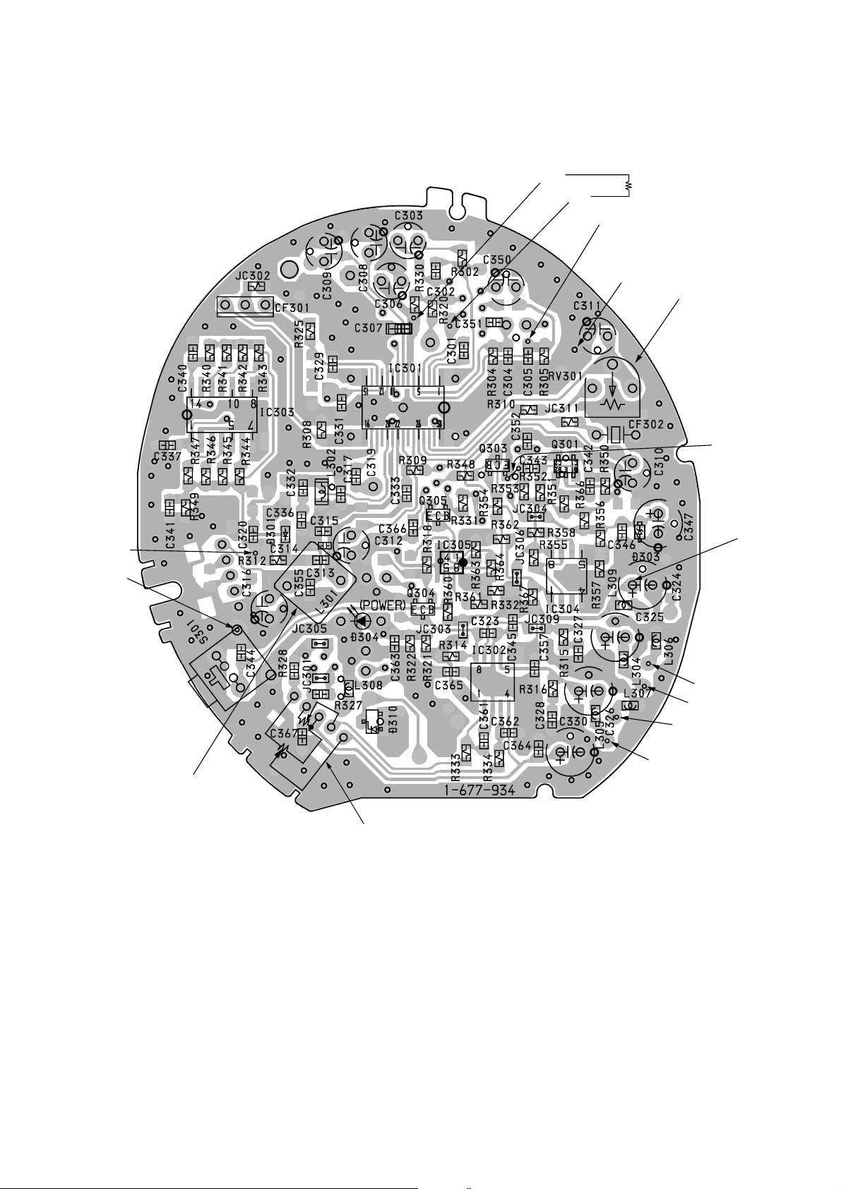
Adjustment Location :
[RX-BASE BOARD]
(Conductor side)
IC301
7
IC301
4
IC301
(Connect a 33 KΩ resistor)
6
GND
TP
GND
RV301
Free Run Frequency
Check and Adjustment
Short
+B
power line
L301
Receive Frequency
Check and Adjustment
L–
L+
R–
R+
RV302
Corrier Modulation/Separation/
MPX Signal Modulation Check
— 9 —
 Loading...