


DCR-TRV360/TRV361/TRV460/TRV460E/TRV461E
|
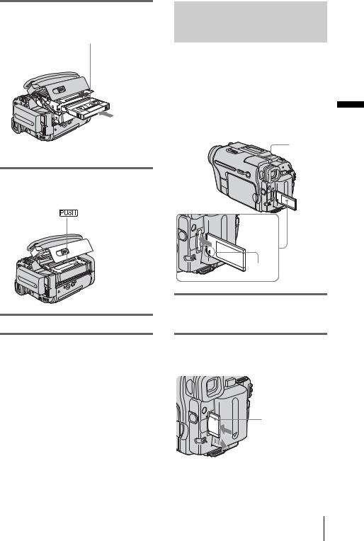
|
|
RMT-831 |
|
|
|
|
|
|
SERVICE MANUAL |
|
|
|
|
|
LEVEL 1 |
|||
|
US Model |
|||
Ver 1.0 2003. 12 |
|
|
||
|
|
DCR-TRV360/TRV460 |
||
Revision History |
|
Canadian Model |
||
|
|
|
DCR-TRV460 |
|
|
|
AEP Model |
||
|
|
|
UK Model |
|
|
|
East European Model |
||
|
|
North European Model |
||
|
|
Australian Model |
||
|
|
|
DCR-TRV460E |
|
|
|
|
E Model |
|
|
|
DCR-TRV361/TRV460/TRV460E/TRV461E |
||
|
|
|
|
|
M2000/M2200 MECHANISM |
Photo: DCR-TRV460 |
|
|
|
|
|
|
|
|
|
|
|
|
|
Link |
|
|
|
|
SPECIFICATIONS |
SELF DIAGNOSIS FUNCTION |
ORNAMENTAL PARTS |
|
|
|
|
|
|
|
• INSTRUCTION MANUAL is shown at the end of this document.


 DIGITAL VIDEO CAMERA RECORDER

DCR-TRV360/TRV361/TRV460/TRV460E/TRV461E
Video camera recorder
System
Video recording system
2 rotary heads, Helical scanning system
Still image recording system
Exif Ver. 2.2*1
*1 Exif is a file format for still images, established by the JEITA (Japan Electronics and Information Technology Industries Association). Files in this format can have additional information such as your camcorder s setting information at the time of recording.
Audio recording system
Rotary heads, PCM system
Quantization: 12 bits (Fs 32 kHz, stereo 1, stereo 2), 16 bits (Fs 48 kHz, stereo)
Video signal
DCR-TRV360/TRV361/TRV460: NTSC color, EIA standards DCR-TRV460E/TRV461E:
PAL color, CCIR standards
Usable cassette
8 mm video format cassette
Tape speed
DCR-TRV360/TRV361/TRV460: SP: Approx. 28.67 mm/s
LP: Approx. 19.11 mm/s DCR-TRV460E/TRV461E: SP: Approx. 28.70 mm/s LP: Approx. 19.13 mm/s
Recording/play back time
DCR-TRV360/TRV361/TRV460:
(using 120 min. Hi8/Digital8 video cassette) DCR-TRV460E/TRV461E:
(using 90 min. Hi8/Digital8 video cassette) SP: 60 min
LP: 90 min
Fast forward/rewind time
DCR-TRV360/TRV361/TRV460:
(using 120 min. Hi8/Digital8 video cassette) DCR-TRV460E/TRV461E:
(using 90 min. Hi8/Digital8 video cassette) Approx. 5 min
Viewfinder
Electric viewfinder (monochrome)
Image device
3.0 mm (1/6 type) CCD (Charge Coupled Device) DCR-TRV360/TRV361/TRV460: Gross: Approx. 460 000 pixels
Effective (still): Approx. 290 000 pixels Effective (movie): Approx. 290 000 pixels DCR-TRV460E/TRV461E:
Gross: Approx. 540 000 pixels Effective (still): Approx. 350 000 pixels
Effective (movie): Approx. 350 000 pixels
Lens
Combined power zoom lens
Filter diameter: 37 mm (1 7/16 in.) 20 × (Optical), 990 × (Digital)
F = 1.6 ~ 2.4
SPECIFICATIONS
Focal length
2.5 - 50 mm (1/8 - 2 in.)
When converted to a 35 mm still camera In CAMERA-TAPE:
42 - 840 mm (1 11/16 - 33 1/8 in.) In CAMERA-MEMORY:
42 - 840 mm (1 11/16 - 33 1/8 in.)
Color temperature
Auto
Minimum illumination
4 lx (lux) (F 1.6)
0 lx (lux) (during the NightShot plus function)*2
*2 Objects unable to be seen due to the dark can be shot with infrared lighting.
Input/Output connectors
S video input/output
Luminance signal: 1 Vp-p, 75 Ω (ohms), unbalanced
Chrominance signal: DCR-TRV360/TRV361/TRV460: 0.286 Vp-p DCR-TRV460E/TRV461E: 0.3 Vp-p
75 Ω (ohms), unbalanced
4-pin mini DIN
Audio/Video input/output
AV MINIJACK
Video signal: 1 Vp-p, 75 Ω (ohms), unbalanced, sync negative
Audio signal: 327 mV (at output impedance more than 47 kΩ (kilohms)), Input impedance more than 47 kΩ (kilohms), Output impedance with less than 2.2 kΩ (kilohms)
Stereo minijack (φ 3.5mm)
DV input/output
4-pin connector
USB jack mini-B
LCD screen
Picture
6.2 cm (2.5 type)
Total dot number
123 200 (560 × 220)
General
Power requirements
DC 7.2 V (battery pack) DC 8.4 V (AC Adaptor)
Average power consumption (when using the battery pack)
During camera recording using the viewfinder 2.9 W
During camera recording using the LCD 3.8 W
Operating temperature
0° C to 40° C (32° F to 104° F)
Storage temperature
-20° C to + 60° C (-4° F to + 140° F)
Dimensions (approx.)
85 × 98 × 151 mm (3 3/8 × 3 7/8 × 6 in.) (w/h/d)
Mass (Approx.)
800 g (1 lb 12 oz) main unit only
940 g (2 lb 1 oz) including the NP-FM30 rechargeable battery pack, Hi8/Digital8 cassette, lens cap, and shoulder strap.
TM
SERIES
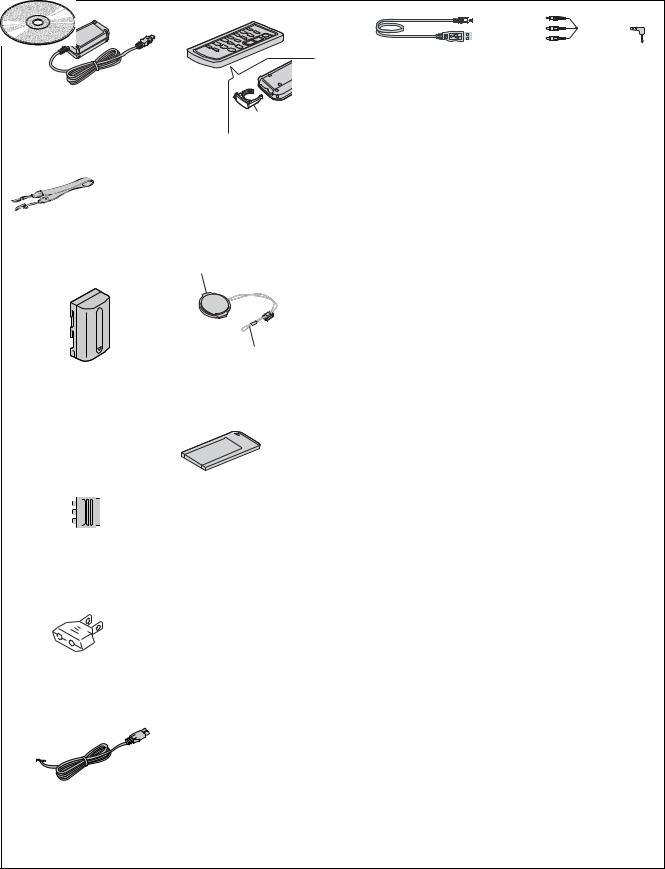
Supplied accessories
Memory Stick 8MB (1)
(DCR-TRV361/TRV461E) AC Adaptor (1)
Power cord (1) Lens cap (1) Shoulder strap (1)
Wireless Remote commander RMT-831 (1) A/V connecting cable (1)
USB cable (1)
Rechargeable battery pack NP-FM30 (1) CD-ROM SPVD-012 USB Driver (1) 21-pin adaptor (1)
(AEP, UK, EE)
Camera Operations Guide (1) Computer Applications Guide (1) See page 7.
AC Adaptor AC-L15A/L15B
Power requirements
AC 100 - 240 V, 50/60 Hz
Current consumption
0.35 - 0.18 A
Power consumption
18 W
Output voltage
DC 8.4 V, 1.5 A
Operating temperature
0° C to 40° C (32° F to 104° F)
Storage temperature
-20° C to + 60° C (-4° F to + 140° F)
Dimensions (approx.)
56 × 31 × 100 mm (2 1/4 × 1 1/4 × 4 in.) (w/h/ d) excluding the projecting parts
Mass (approx.)
190 g (6.7 oz) excluding the power cord
Rechargeable battery pack (NP-FM30)
Maximum output voltage
DC 8.4 V
Output voltage
DC 7.2 V
Capacity
5.0 Wh (700 mAh)
Dimensions (approx.)
38.2 × 20.5 × 55.6 mm
(1 9/16 × 1 3/16 × 2 1/4 in.) (w/h/d)
Mass (approx.)
65 g (2.3 oz)
Operating temperature
0° C to 40° C (32° F to 104° F)
Type
Lithium ion
Design and specifications are subject to change without notice.
— 2 —

DCR-TRV360/TRV361/TRV460/TRV460E/TRV461E
Table for differences of function
Model |
DCR-TRV360 |
DCR-TRV361 |
DCR-TRV460 |
DCR-TRV460E |
DCR-TRV461E |
||
|
|
|
|
|
|
|
|
Destination |
US |
E |
US, CND, E |
AEP, UK, EE |
E |
||
NE, E, AUS |
|||||||
|
|
|
|
|
|
||
|
|
|
|
|
|
||
Color system |
NTSC |
NTSC |
NTSC |
PAL |
PAL |
||
|
|
|
|
|
|
||
Playback system |
Digital8 |
Digital8 |
Hi8/8/Digital8 |
Hi8/8/Digital8 |
Hi8/8/Digital8 |
||
|
|
|
|
|
|
||
Mechanism deck |
M2200 |
M2200 |
M2000 |
M2000 |
M2000 |
||
|
|
|
|
|
|
|
|
• Abbreviation |
|
|
|
|
|
|
|
AUS : Australian model |
EE |
: East European model |
|
|
|
||
CND : Canadian model |
NE |
: North European model |
|
|
|
||
SAFETY-RELATED COMPONENT WARNING!!
COMPONENTS IDENTIFIED BY MARK 0OR DOTTED LINE WITH MARK 0 ON THE SCHEMATIC DIAGRAMS AND IN THE PARTS
LIST ARE CRITICAL TO SAFE OPERATION. REPLACE THESE COMPONENTS WITH SONY PARTS WHOSE PART NUMBERS APPEAR AS SHOWN IN THIS MANUAL OR IN SUPPLEMENTS PUBLISHED BY SONY.
ATTENTION AU COMPOSANT AYANT RAPPORT
À LA SÉCURITÉ!
LES COMPOSANTS IDENTIFÉS PAR UNE MARQUE 0 SUR LES
DIAGRAMMES SCHÉMATIQUES ET LA LISTE DES PIÈCES SONT CRITIQUES POUR LA SÉCURITÉ DE FONCTIONNEMENT. NE REMPLACER CES COMPOSANTS QUE PAR DES PIÈSES SONY DONT LES NUMÉROS SONT DONNÉS DANS CE MANUEL OU DANS LES SUPPÉMENTS PUBLIÉS PAR SONY.
SAFETY CHECK-OUT
After correcting the original service problem, perform the following
safety checks before releasing the set to the customer.
1.Check the area of your repair for unsoldered or poorly-soldered connections. Check the entire board surface for solder splashes and bridges.
2.Check the interboard wiring to ensure that no wires are "pinched" or contact high-wattage resistors.
3.Look for unauthorized replacement parts, particularly transistors, that were installed during a previous repair. Point them out to the customer and recommend their replacement.
4.Look for parts which, through functioning, show obvious signs of deterioration. Point them out to the customer and recommend their replacement.
5.Check the B+ voltage to see it is at the values specified.
6.Flexible Circuit Board Repairing
•Keep the temperature of the soldering iron around 270˚C during repairing.
•Do not touch the soldering iron on the same conductor of the circuit board (within 3 times).
•Be careful not to apply force on the conductor when soldering or unsoldering.
Unleaded solder
Boards requiring use of unleaded solder are printed with the leadfree mark (LF) indicating the solder contains no lead.
(Caution: Some printed circuit boards may not come printed with the lead free mark due to their particular size.)
 : LEAD FREE MARK
Unleaded solder has the following characteristics.
•Unleaded solder melts at a temperature about 40°C higher than ordinary solder.
Ordinary soldering irons can be used but the iron tip has to be applied to the solder joint for a slightly longer time.
Soldering irons using a temperature regulator should be set to about 350°C.
Caution: The printed pattern (copper foil) may peel away if the heated tip is applied for too long, so be careful!
•Strong viscosity
Unleaded solder is more viscous (sticky, less prone to flow) than ordinary solder so use caution not to let solder bridges occur such as on IC pins, etc.
•Usable with ordinary solder
It is best to use only unleaded solder but unleaded solder may also be added to ordinary solder.
— 3 —

DCR-TRV360/TRV361/TRV460/TRV460E/TRV461E
SELF-DIAGNOSIS FUNCTION
1. Self-diagnosis Function
When problems occur while the unit is operating, the self-diagnosis function starts working, and displays on the viewfinder or Display window what to do. This function consists of two display; selfdiagnosis display and service mode display.
Details of the self-diagnosis functions are provided in the Instruction manual.
2. Self-diagnosis Display
When problems occur while the unit is operating, the counter of the viewfinder or Display window shows a 4-digit display consisting of an alphabet and numbers, which blinks at 3.2 Hz. This 5-character display indicates the “repaired by:”, “block” in which the problem occurred, and “detailed code” of the problem.
Viewfinder Display window
C : 3 1 : 1 1 |
C : 3 1 : 11 |
|
|
|
|
Blinks at 3.2Hz
C 


 3 1
3 1 

 1 1
1 1
Repaired by:
C : Corrected by customer H : Corrected by dealer
E : Corrected by service engineer
|
|
Block |
|
|
Detailed Code |
|
|
|
|
|
|
|
|
Indicates the appropriate |
Refer to 4. Self-diagnosis Code Table . |
|||||
step to be taken. |
|
|
|
|||
E.g. |
|
|
|
|||
31 |
....Reload the tape. |
|
|
|
||
32 |
....Turn on power again. |
|
|
|
||
— 4 —
DCR-TRV360/TRV361/TRV460/TRV460E/TRV461E
4. Self-diagnosis Code Table
|
Self-diagnosis Code |
|
|
|
|||
by: |
|
Block |
Detailed |
Symptom/State |
Correction |
||
Repaired |
|
||||||
|
Function |
Code |
|
|
|||
|
|
|
|
||||
|
|
|
|
|
|
|
|
C |
|
0 |
4 |
0 |
0 |
Non-standard battery is used. |
Use the InfoLITHIUM battery. |
|
|
|
|
|
|
|
|
C |
|
2 |
1 |
0 |
0 |
Condensation. |
Remove the cassette, and insert it again after one hour. |
|
|
|
|
|
|
|
|
C |
|
2 |
2 |
0 |
0 |
Video head is dirty. |
Clean with the optional cleaning cassette. |
|
|
|
|
|
|
|
|
C |
|
3 |
1 |
1 |
0 |
LOAD direction. Loading does not |
Load the tape again, and perform operations from the beginning. |
|
complete within specified time |
||||||
|
|
|
|
|
|
|
|
|
|
|
|
|
|
|
|
C |
|
3 |
1 |
1 |
1 |
UNLOAD direction. Loading does not |
Load the tape again, and perform operations from the beginning. |
|
complete within specified time |
||||||
|
|
|
|
|
|
|
|
|
|
|
|
|
|
|
|
C |
|
3 |
1 |
2 |
0 |
T reel side tape slacking when unloading. |
Load the tape again, and perform operations from the beginning. |
|
|
|
|
|
|
|
|
C |
|
3 |
1 |
2 |
1 |
S reel side tape slacking when unloading. |
Load the tape again, and perform operations from the beginning. |
|
|
|
|
|
|
|
|
C |
|
3 |
1 |
2 |
2 |
T reel fault. |
Load the tape again, and perform operations from the beginning. |
|
|
|
|
|
|
|
|
C |
|
3 |
1 |
2 |
3 |
S reel fault. |
Load the tape again, and perform operations from the beginning. |
|
|
|
|
|
|
|
|
C |
|
3 |
1 |
3 |
0 |
FG fault when starting capstan. |
Load the tape again, and perform operations from the beginning. |
|
|
|
|
|
|
|
|
C |
|
3 |
1 |
3 |
1 |
FG fault during normal capstan operations. |
Load the tape again, and perform operations from the beginning. |
|
|
|
|
|
|
|
|
C |
|
3 |
1 |
4 |
0 |
FG fault when starting drum. |
Load the tape again, and perform operations from the beginning. |
|
|
|
|
|
|
|
|
C |
|
3 |
1 |
4 |
1 |
PG fault when starting drum. |
Load the tape again, and perform operations from the beginning. |
|
|
|
|
|
|
|
|
C |
|
3 |
1 |
4 |
2 |
FG fault during normal drum operations. |
Load the tape again, and perform operations from the beginning. |
|
|
|
|
|
|
|
|
C |
|
3 |
1 |
4 |
3 |
PG fault during normal drum operations. |
Load the tape again, and perform operations from the beginning. |
|
|
|
|
|
|
|
|
C |
|
3 |
1 |
4 |
4 |
Phase fault during normal drum operations. |
Load the tape again, and perform operations from the beginning. |
|
|
|
|
|
|
|
|
C |
|
3 |
2 |
1 |
0 |
LOAD direction loading motor time- |
Remove the battery or power cable, connect, and perform |
|
out. |
operations from the beginning. |
|||||
|
|
|
|
|
|
||
|
|
|
|
|
|
|
|
C |
|
3 |
2 |
1 |
1 |
UNLOAD direction loading motor |
Remove the battery or power cable, connect, and perform |
|
time-out. |
operations from the beginning. |
|||||
|
|
|
|
|
|
||
|
|
|
|
|
|
|
|
C |
|
3 |
2 |
2 |
0 |
T reel side tape slacking when |
Remove the battery or power cable, connect, and perform |
|
unloading. |
operations from the beginning. |
|||||
|
|
|
|
|
|
||
|
|
|
|
|
|
|
|
C |
|
3 |
2 |
2 |
1 |
S reel side tape slacking when |
Remove the battery or power cable, connect, and perform |
|
unloading. |
operations from the beginning. |
|||||
|
|
|
|
|
|
||
|
|
|
|
|
|
|
|
C |
|
3 |
2 |
2 |
2 |
T reel fault. |
Remove the battery or power cable, connect, and perform |
|
operations from the beginning. |
||||||
|
|
|
|
|
|
|
|
|
|
|
|
|
|
|
|
C |
|
3 |
2 |
2 |
3 |
S reel fault. |
Remove the battery or power cable, connect, and perform |
|
operations from the beginning. |
||||||
|
|
|
|
|
|
|
|
|
|
|
|
|
|
|
|
C |
|
3 |
2 |
3 |
0 |
FG fault when starting capstan. |
Remove the battery or power cable, connect, and perform |
|
operations from the beginning. |
||||||
|
|
|
|
|
|
|
|
|
|
|
|
|
|
|
|
C |
|
3 |
2 |
3 |
1 |
FG fault during normal capstan |
Remove the battery or power cable, connect, and perform |
|
operations. |
operations from the beginning. |
|||||
|
|
|
|
|
|
||
|
|
|
|
|
|
|
|
C |
|
3 |
2 |
4 |
0 |
FG fault when starting drum. |
Remove the battery or power cable, connect, and perform |
|
operations from the beginning. |
||||||
|
|
|
|
|
|
|
|
|
|
|
|
|
|
|
|
C |
|
3 |
2 |
4 |
1 |
PG fault when starting drum. |
Remove the battery or power cable, connect, and perform |
|
operations from the beginning. |
||||||
|
|
|
|
|
|
|
|
|
|
|
|
|
|
|
|
C |
|
3 |
2 |
4 |
2 |
FG fault during normal drum |
Remove the battery or power cable, connect, and perform |
|
operations. |
operations from the beginning. |
|||||
|
|
|
|
|
|
||
|
|
|
|
|
|
|
|
C |
|
3 |
2 |
4 |
3 |
PG fault during normal drum |
Remove the battery or power cable, connect, and perform |
|
operations. |
operations from the beginning. |
|||||
|
|
|
|
|
|
||
|
|
|
|
|
|
|
|
C |
|
3 |
2 |
4 |
4 |
Phase fault during normal drum |
Remove the battery or power cable, connect, and perform |
|
operations. |
operations from the beginning. |
|||||
|
|
|
|
|
|
||
|
|
|
|
|
|
|
|
— 5 —

DCR-TRV360/TRV361/TRV460/TRV460E/TRV461E
1. MAIN PARTS
Note:
•Items marked “*” are not stocked since they are seldom required for routine service. Some delay should be anticipated when ordering these items.
•The parts numbers of such as a cabinet are also appeared in this section. Refer to the parts number mentioned below the name of parts to order.
•Abbreviation
AUS : Australian model CND : Canadian model
EE |
: East European model |
NE |
: North European model |
The components identified by mark 0 or dotted line with mark 0 are critical for safety.
Replace only with part number specified.
Les composants identifiés par une marque 0 sont critiquens pour la sécurité.
Ne les remplacer que par une pièce portant le numéro spécifié.
1. ORNAMENTAL PARTS
S terminal cover (51) 3-087-749-01 (When change it,
need dismantle the set.)
|
Jack cover (51) |
|
3-087-813-01 |
|
(When change it, |
CPC lid (51) |
need dismantle the set.) |
3-087-810-01 |
|
P2 Lock ace Screw (M2)
3-080-203-31
Jack lid (2500) 3-072-305-01 (When change it,
need dismantle the set.)
— 6 —
DCR-TRV360/TRV361/TRV460/TRV460E/TRV461E
Checking supplied accessories.
AC-L15A/L15B AC Adaptor (1)
01-477-533-32 (TRV461E)
01-477-533-51
(EXCEPT TRV461E)
Shoulder strap (1) 3-987-015-01
Rechargeable battery pack NP-FM30 (1)
0A-7096-387-A (US, CND)
0A-7096-388-B
(EXCEPT US, CND)
21-pin adaptor (1)
1-770-783-21
(AEP, UK, NE, EE)
Battery holder 3-083-973-01
Wireless Remote Commander RMT-831 (1)
1-477-898-41
(EXCEPT TRV461E) 1-477-898-61 (TRV461E)
Lens cap (1)
X-3952-971-1
Cap string (1) 3-979-194-12
Memory Stick 8MB (1)
|
CD-ROM |
|
(SPVD-012 (V) USB Driver) (1) |
Conversion 2P adaptor (1) |
3-086-790-01 (US, CND) |
0 1-569-008-12 |
(SPVD-012 USB Driver) (1) |
(TRV361: E, TRV460: E, |
3-087-821-01 |
TRV461: E) |
(EXCEPT US, CND) |
Power cord (1)
01-696-819-21 (AUS)
01-769-608-11 (AEP, NE, EE, E)
01-783-374-11 (UK)
01-790-542-12 (US, CND)
|
|
|
|
|
|
|
|
|
|
|
|
|
|
|
|
|
|
|
|
|
|
|
|
USB cable (1) |
|
A/V connecting cable (1) |
|||
1-823-931-21 |
|
1-824-097-41 |
|
||
Other accessories
CAMERA OPERATIONS GUIDE
3-087-921-11 MANUAL, INSTRUCTION (ENGLISH)
(TRV360/TRV361/TRV460)
3-087-921-21 MANUAL, INSTRUCTION (FRENCH) (TRV460: CND) 3-087-921-31 MANUAL, INSTRUCTION (SPANISH, PORTUGUESE)
(TRV361/TRV460: E) 3-087-921-41 MANUAL, INSTRUCTION (TRADITIONAL CHINESE)
(TRV460: E)
3-087-923-11 MANUAL, INSTRUCTION (ENGLISH)
(TRV460E: AEP, UK, E, AUS/TRV461E)
3-087-923-21 MANUAL, INSTRUCTION (FRENCH) (TRV460E: AEP, E)
3-087-923-31 MANUAL, INSTRUCTION (SPANISH, PORTUGUESE) (TRV460E: AEP)
3-087-923-41 MANUAL, INSTRUCTION (ITALIAN, GREEK)
(TRV460E: AEP)
3-087-923-51 MANUAL, INSTRUCTION (GERMAN, DUTCH)
(TRV460E: AEP) 3-087-923-61 MANUAL, INSTRUCTION (SWEDISH, RUSSIAN)
(TRV460E: NE) 3-087-923-71 MANUAL, INSTRUCTION (DANISH, FINNISH)
(TRV460E: NE) 3-087-923-81 MANUAL, INSTRUCTION (POLISH, CZECH) (TRV460E: EE) 3-087-923-91 MANUAL, INSTRUCTION (HUNGALIAN, SLOVAKIAN)
(TRV460E: EE) 3-087-924-11 MANUAL, INSTRUCTION (ARABIC, PERSIAN)
(TRV460E: E/TRV461E) 3-087-924-31 MANUAL, INSTRUCTION (SIMPLIFIED CHINESE)
(TRV460E: E)
COMPUTER APPLICATIONS GUIDE
3-087-936-11 MANUAL (PC), INSTRUCTION (ENGLISH)
(EXCEPT TRV460E: AEP, NE, EE)
3-087-936-21 MANUAL (PC), INSTRUCTION (FRENCH)
(TRV460: CND/TRV460E: AEP, E)
3-087-936-31 MANUAL (PC), INSTRUCTION (GERMAN, DUTCH) (TRV460E: AEP)
3-087-936-41 MANUAL (PC), INSTRUCTION (SPANISH, PORTUGUESE) (TRV361/TRV460: E/TRV460E: AEP)
3-087-936-51 MANUAL (PC), INSTRUCTION (ITALIAN, GREEK) (TRV460E: AEP)
3-087-936-61 MANUAL (PC), INSTRUCTION (SWEDISH, RUSSIAN) (TRV460E: NE)
3-087-936-71 MANUAL (PC), INSTRUCTION (DANISH, FINNISH)
(TRV460E: NE) 3-087-936-81 MANUAL (PC), INSTRUCTION (POLISH, CZECH)
(TRV460E: EE) 3-087-936-91 MANUAL (PC), INSTRUCTION (HUNGALIAN, SLOVAKIAN)
(TRV460E: EE) 3-087-937-11 MANUAL (PC), INSTRUCTION (ARABIC, PERSIAN)
(TRV460E: E/TRV461E) 3-087-937-21 MANUAL (PC), INSTRUCTION (TRADITIONAL CHINESE)
(TRV460: E) 3-087-937-31 MANUAL (PC), INSTRUCTION (SIMPLIFIED CHINESE)
(TRV460E: E)
The components identified by |
Les composants identifiés par une |
mark 0 or dotted line with |
marque 0 sont critiques pour la |
mark 0are critical for safety. |
sécurité. |
Replace only with part num- |
Ne les remplacer que par une pièce |
ber specified. |
portant le numéro spécifié. |
|
|
— 7 —
DCR-TRV360/TRV361/TRV460/TRV460E/TRV461E
9-876-293-41 |
Sony EMCS Co. |
|
— 8 — |
2003L0500-1 ©2003.12
Published by DI CS Strategy Div

[US] Guide Operations Camera
3-087-921-11(1)
Camera
Operations Guide
Read this first
Digital Video Camera Recorder
DCR-TRV360/TRV361/
TRV460
TM
SERIES
© 2004 Sony Corporation

Read this first
Before operating the unit, please read this manual thoroughly, and retain it for future reference.
WARNING
To prevent fire or shock hazard, do not expose the unit to rain or moisture.
This symbol is intended to alert the user to the presence of uninsulated “dangerous voltage” within the product’s enclosure that may be of sufficient magnitude to constitute a risk of electric shock to persons.
This symbol is intended to alert the user to the presence of important operating and maintenance (servicing) instructions in the literature accompanying the appliance.
b Notice
•If static electricity or electromagnetic interference causes data transfer to discontinue midway (fail), restart the application or disconnect and connect the USB cable again.
For customers in the U.S.A. and CANADA
CAUTION
TO PREVENT ELECTRIC SHOCK, MATCH WIDE BLADE OF PLUG TO WIDE SLOT, FULLY INSERT.
RECYCLING LITHIUM-ION BATTERIES
Lithium-Ion batteries are recyclable.
You can help preserve our environment by returning your used rechargeable batteries to the collection and recycling location nearest you. For more information
regarding recycling of rechargeable batteries, call toll free 1-800-822-8837, or visit http://www.rbrc.org/
Caution: Do not handle damaged or leaking LithiumIon batteries.
2
For customers in the U.S.A.
If you have any questions about this product, you may call:
Sony Customer Information Center 1-800-222-SONY (7669)
The number below is for FCC related matters only. Regulatory Information
Declaration of Conformity
Trade Name: SONY
Model No.: DCR-TRV360/TRV460 Responsible Party: Sony Electronics Inc. Address: 680 Kinderkamack Road, Oradell, NJ 07649 U.S.A.
Telephone No.: 201-930-6972
This device complies with Part 15 of the FCC Rules. Operation is subject to the following two conditions:
(1) This device may not cause harmful interference, and (2) this device must accept any interference received, including interference that may cause undesired operation.
Owner’s Record
The model and serial numbers are located on the bottom. Record the serial number in the space provided below. Refer to these numbers whenever you call upon your Sony dealer regarding this product. Model No. DCR-TRV
Serial No. Model No. ACSerial No.
CAUTION
You are cautioned that any changes or modifications not expressly approved in this manual could void your authority to operate this equipment.
b Note:
This equipment has been tested and found to comply with the limits for a Class B digital device, pursuant to Part 15 of the FCC Rules.
These limits are designed to provide reasonable protection against harmful interference in a residential installation. This equipment generates, uses, and can radiate radio frequency energy and, if not installed and used in accordance with the instructions, may cause harmful interference to radio communications. However, there is no guarantee that interference will not occur in a particular installation. If this equipment does cause harmful interference to radio or television reception, which can be determined by turning the equipment off and on, the user is encouraged to try to correct the interference by one or more of the following measures:
–Reorient or relocate the receiving antenna.
–Increase the separation between the equipment and receiver.
–Connect the equipment to an outlet on a circuit different from that to which the receiver is connected.
–Consult a Sony dealer or an experienced radio/TV
technician for help.
The interface cable supplied must be used with the equipment in order to comply with the limits for a digital device pursuant to Subpart B of Part 15 of FCC Rules.
Notes on use
Note on a cassette tape
You can record on standard 8 mm  and Hi8
 , Digital8
  video cassettes in Digital8
  system only on your camcorder. See page 115 for details.
Notes on recording
•Before starting to record, test the recording function to make sure the picture and sound are recorded without any problems.
•Compensation for the contents of recordings cannot be provided, even if recording or playback is not possible due to a malfunction of the camcorder, storage media, etc.
•TV color systems differ depending on the country/ regions. To view your recordings on a TV, you need an NTSC system-based TV.
•Television programs, films, video tapes, and other materials may be copyrighted. Unauthorized recording of such materials may be contrary to the copyright laws.
Notes on the LCD panel, viewfinder, and lens
•The LCD screen and the viewfinder are manufactured using extremely high-precision technology, so over 99.99% of the pixels are operational for effective use.
However, there may be some tiny black points and/ or bright points (white, red, blue, or green in color) that appear constantly on the LCD screen and the viewfinder.
These points are normal results of the manufacturing process and do not affect the recording in any way.
,continued
3
•Exposing the LCD screen, the viewfinder, or the lens to direct sunlight for long periods of time may cause malfunctions. Be careful when placing the camera near a window or outdoors.
•Do not aim at the sun. Doing so might cause your camcorder to malfunction. Take pictures of the sun only in low light conditions, such as at dusk.
Note on connecting other device
Before connecting your camcorder to other device such as a VCR or a computer with a USB or i.LINK cable, be sure to insert the connector plug in the proper direction. If you insert the connector plug forcibly in the wrong direction, the terminal may be damaged, or this may cause a malfunction of your camcorder.
Notes on using this manual
•The images of the LCD screen and the viewfinder used on this manual are captured using a digital still camera, and thus may appear different from what you see.
•Instructions with no specific model names are for all models.
Instructions with specific model names are for the indicated models only.
Before you start reading this manual, check the model name of your camcorder.
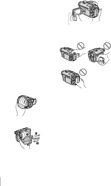
Notes on using the camcorder
• Hold your camcorder correctly.
•To ensure a good grip, fasten the grip belt as shown in the following illustration.
•When you are using the touch panel, place your hand on the back side of the LCD panel to support it. Then, touch the buttons displayed on the screen.
Touch the button on the LCD screen.
•You can change the language to be used for screen display on your camcorder (p. 22)
•Do not hold the camcorder by the following parts.
Viewfinder |
LCD panel |
Battery pack
4

Table of Contents
 : Features available for tape only.
 : Features available for “Memory Stick” only.
Read this first ............................................................................................. |
|
2 |
Quick Start Guide |
|
|
Recording movies ...................................................................................... |
|
8 |
Recording still images .............................................................................. |
|
10 |
Recording/Playing back with ease ........................................................... |
12 |
|
Getting started |
|
|
Step 1: Checking supplied items.............................................................. |
13 |
|
Step 2: Charging the battery pack............................................................ |
14 |
|
Using an outside power source ................................................................................. |
17 |
|
Step 3: Turning the power on................................................................... |
17 |
|
Step 4: Adjusting the LCD panel and viewfinder...................................... |
18 |
|
Adjusting the LCD panel |
........................................................................................... |
18 |
Adjusting the viewfinder ............................................................................................ |
|
18 |
Step 5: Setting the date and time............................................................. |
19 |
|
Step 6: Inserting the recording media ...................................................... |
20 |
|
Inserting a cassette tape |
........................................................................................... |
20 |
Inserting a “Memory Stick” ........................................................................................ |
21 |
|
Step 7: Setting the screen language ........................................................ |
22 |
|
Recording |
|
|
Recording movies .................................................................................... |
|
24 |
Recording for a longer time ....................................................................................... |
26 |
|
Using zoom ............................................................................................................... |
|
26 |
Using the built-in light ................................................................................................ |
|
27 |
Recording in mirror mode |
......................................................................................... |
28 |
Using the self-timer ................................................................................................... |
|
28 |
Recording still images |
– Memory photo recording............................. |
29 |
Selecting image quality ............................................................................................. |
|
31 |
Using the self-timer ................................................................................................... |
|
31 |
Recording a still image on a “Memory Stick” while recording movies on a tape ....... |
32 |
|
Recording with ease – Easy Handycam .................................................. |
33 |
|
Recording a movie .............................................................................................. |
|
33 |
Recording a still image |
........................................................................................ |
34 |
Making full use of Easy Handycam operation ........................................................... |
34 |
|
|
,continued |
|
5

Adjusting the exposure............................................................................. |
|
|
35 |
Adjusting the exposure for backlit subjects ............................................................... |
35 |
||
Fixing the exposure for the selected subject – Flexible spot meter ........................... |
35 |
||
Adjusting the exposure manually |
............................................................................... |
36 |
|
Recording in dark places – NightShot . ......................................plus, etc |
37 |
||
Adjusting the focus................................................................................... |
|
|
38 |
Adjusting the focus for an off-center ..................................subject – SPOT FOCUS |
38 |
||
Adjusting the focus manually ..................................................................................... |
|
39 |
|
Recording a picture using various ................................................effects |
40 |
||
Fading in and out of a scene .............................................................. |
– FADER |
40 |
|
Using special effects |
– Digital ...................................................................effect |
41 |
|
Overlaying still images on movies ..................................on a tape – MEMORY MIX |
42 |
||
Searching for the starting point .......................................................... |
|
44 |
|
Searching for the last scene of the most recent recording |
|
||
– END SEARCH .................................................................................................. |
|
|
44 |
Searching manually – EDIT SEARCH ....................................................................... |
45 |
||
Reviewing the most recently recorded ....................................scenes – Rec review |
45 |
||
Playback |
|
|
|
Viewing movies recorded on a tape ................................................... |
46 |
||
Playing back in various modes .................................................................................. |
|
47 |
|
Viewing recordings with added effects ..............................................– Digital effect |
48 |
||
Viewing recordings on a “Memory ...........................................Stick” |
49 |
||
Playing back in various modes from ..............................................a “Memory Stick” |
50 |
||
Playing back with ease – Easy Handycam .............................................. |
51 |
||
Making full use of Easy Handycam ...........................................................operation |
52 |
||
Various playback functions |
...................................................................... |
|
53 |
Magnifying pictures – Tape playback .......................zoom/Memory playback zoom |
53 |
||
Displaying the screen indicators ................................................................................ |
|
54 |
|
Displaying the date/time and camera ..............................settings data – Data code |
54 |
||
Playing the picture on a TV ...................................................................... |
|
56 |
|
Locating a scene on a tape for playback ........................................... |
57 |
||
Searching quickly for a desired scene ........................................– Zero set memory |
57 |
||
Searching for a scene by date of .......................................recording – Date search |
57 |
||
6
Advanced operations |
|
|
Using the Menu |
|
|
Selecting menu items ......................... |
59 |
|
Using the |
(CAMERA SET) menu |
|
– PROGRAM AE/16:9 WIDE, |
|
|
etc. ............................................... |
|
61 |
Using the |
(MEMORY SET) menu |
|
– QUALITY/IMAGE SIZE/ALL |
|
|
ERASE/NEW FOLDER, etc. ........ |
65 |
|
Using the |
(PICT. APPLI.) menu |
|
– PICT. EFFECT/SLIDE SHOW/ |
|
|
FRAME REC/INTERVAL REC, |
|
|
etc. ............................................... |
|
68 |
Using the |
(EDIT/PLAY) menu |
|
– END SEARCH/TITLE, etc. ........ |
73 |
|
Using the |
(STANDARD SET) menu |
|
– REC MODE/MULTI-SOUND/ |
|
|
AUDIO MIX/USB-CAMERA, |
|
|
etc. ............................................... |
|
76 |
Using the |
(TIME/LANGU.) menu |
|
– CLOCK SET/WORLD TIME, |
|
|
etc. ............................................... |
|
82 |
Customizing Personal Menu .............. |
83 |
|
Dubbing/Editing |
|
|
Connecting to a VCR or TV ............... |
86 |
|
Dubbing to another tape ............... |
87 |
|
Recording pictures from a VCR or |
|
|
TV ................................................. |
|
88 |
Dubbing pictures from a tape to a |
|
|
“Memory Stick” ............................. |
89 |
|
Dubbing still images from a “Memory |
||
Stick” to a tape ............................. |
90 |
|
Dubbing selected scenes from a tape |
|
|
– Digital program editing .............. |
91 |
|
Deleting recorded pictures ............ |
98 |
|
Marking recorded images with specific |
|
information – Image protection/ |
|
Print mark ..................................... |
99 |
Printing recorded images (PictBridge |
|
compliant printer) .................. |
101 |
Troubleshooting |
|
Troubleshooting ............................... |
103 |
Warning indicators and messages ... |
110 |
Additional Information |
|
Using your camcorder abroad .......... |
114 |
Usable cassette tapes ...................... |
115 |
About the “Memory Stick” ................. |
116 |
About the “InfoLITHIUM” battery |
|
pack ............................................ |
118 |
About i.LINK ..................................... |
119 |
Maintenance and precautions .......... |
120 |
Specification ..................................... |
123 |
Quick Reference |
|
Identifying parts and controls ........... |
126 |
Index ................................................ |
132 |
Refer also to other operating instructions supplied with your camcorder:
•Editing images with your computer cComputer Applications Guide
7

Quick Start Guide
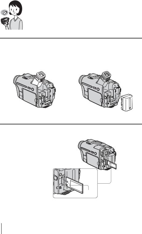
Recording movies
1 Attach the charged battery pack to the camcorder.
To charge the battery, see page 14.
a Lift up the viewfinder. b Slide the battery pack in the direction of the arrow until it clicks.
2 Insert a cassette into the camcorder.
a Slide the |
OPEN/ |
b Insert the cassette with |
EJECT lever in the |
its window-side facing |
|
direction of the arrow |
up, then push the center |
|
to open the lid. |
of the back of the |
|
The cassette compartment |
cassette. |
|
comes out automatically. |
|
|
cPress  .
.
Close the cassette lid after the cassette compartment slides back in by itself.
Window-side
 OPEN/EJECT lever
8 Quick Start Guide
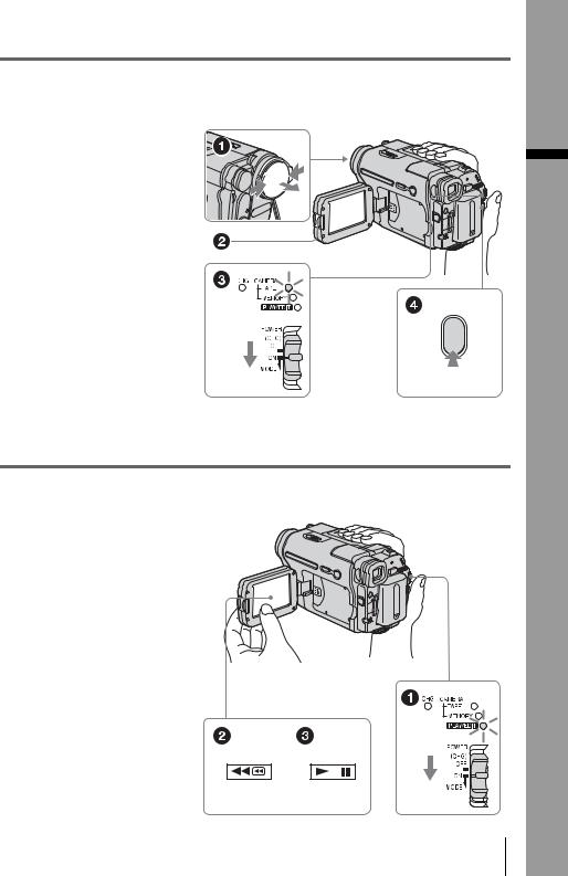
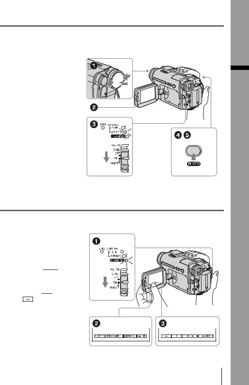
3 Start recording while checking the subject on the LCD screen.
The date and time is not set up in the default setting. To set the date and time, see page 19.
a Remove the lens cap.
Lens cap is not attached when you purchase your camcorder (p. 126).
b Press OPEN and
open the LCD panel.
c While pressing the green button, slide the POWER switch down to light up the CAMERA-TAPE lamp.
The power turns on.
d Press REC START/
STOP.
Recording starts. To change to standby mode, press REC START/STOP again.
4 View the recorded picture on the LCD screen.
a Slide the POWER switch repeatedly until the PLAY/EDIT lamp lights up.
b Touch  (rewind).
c Touch  (play) to start the playback.
To stop, press  .
.
To turn off the power, slide the
POWER switch up to (CHG)
OFF.
Guide Start Quick
Quick Start Guide 9
Recording still images
1 Attach the charged battery pack to the camcorder.
To charge the battery, see page 14.
a Lift up the viewfinder. b Slide the battery pack in the direction of the arrow until it clicks.
2 Insert a “Memory Stick” into the camcorder.
Insert it so that the b mark is at the bottom left corner. Push in until it clicks.
b mark
10 Quick Start Guide
3 Start recording while checking the subject on the LCD screen.
The date and time is not set up in the default setting. To set the date and time, see page 19.
a Remove the lens cap.
Lens cap is not attached when you purchase your camcorder (p. 126).
b Press OPEN and
open the LCD panel.
c While pressing the green button, slide the POWER switch repeatedly until the CAMERA-MEMORY lamp lights up.
The power turns on.
d Press PHOTO lightly.
A short beep sound is heard when the focus is adjusted.
ePress PHOTO fully.
A shutter sound is heard and the still image is recorded.
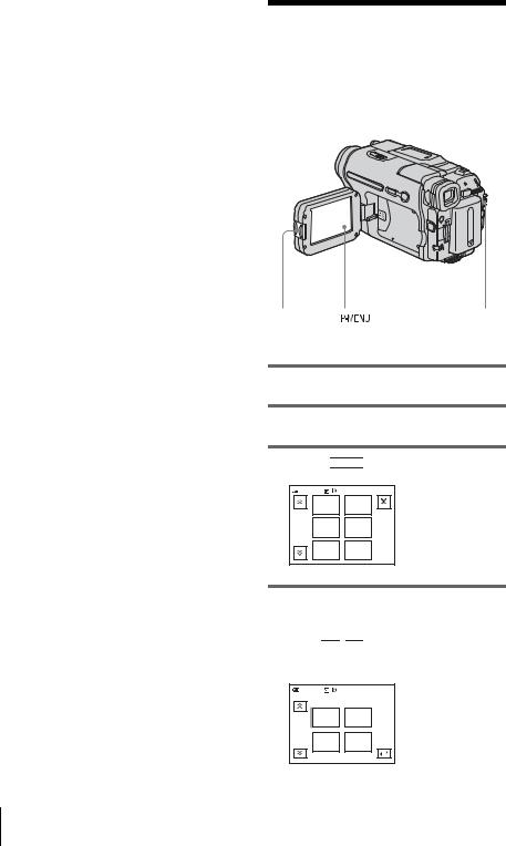
4 View the recorded picture on the LCD screen.
a Slide the POWER switch repeatedly until the PLAY/EDIT lamp lights up.
b Touch 

 .
.
The most recently recorded image is displayed.
c Touch  (next) or
(previous) to
view images in sequence.
To turn off the power, slide the
POWER switch up to (CHG)
OFF.
Guide Start Quick
Quick Start Guide 11
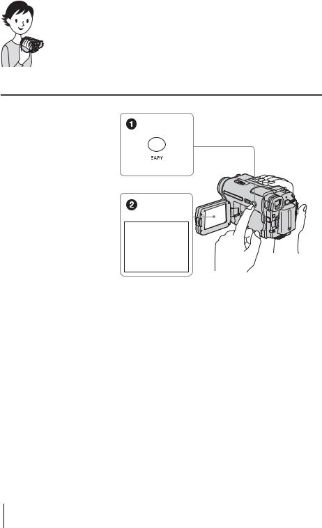
Recording/Playing back with ease
By switching to Easy Handycam operation, recording/playback operation becomes even easier.
Easy Handycam operation allows easy recording/playback for even first time users by providing only the basic functions for recording/playback.
Press EASY when recording/ playing back.
EASY lights up in blue (1) and screen font size increases (2) during Easy Handycam operation.
Easy Handycam operation
ON
For details, see instructions for each operation.
See page 33 for recording, page 51 for playback.
12 Quick Start Guide
Getting started
Step 1: Checking supplied items
Make sure you have following items supplied with your camcorder.
The number in parentheses indicates the number of that item supplied.
“Memory Stick” 8MB (1) (DCR-TRV361)
Memory Stick media is only supplied with DCR-TRV361.
There is no Memory Stick media supplied with DCR-TRV360/TRV460.
AC Adaptor (1)
Power cord (1)
Lens cap (1)
See page 126 on how to attach the lens cap.
Shoulder strap (1)
See page 127 on how to attach the shoulder strap.
Wireless Remote Commander (1)
A button-type lithium battery is already installed.
A/V connecting cable (1)
USB cable (1)
Rechargeable battery pack NP-FM30 (1)
CD-ROM “SPVD-012 USB Driver” (1)
Camera Operations Guide (This manual) (1)
Computer Applications Guide (1)
started Getting
Getting started 13
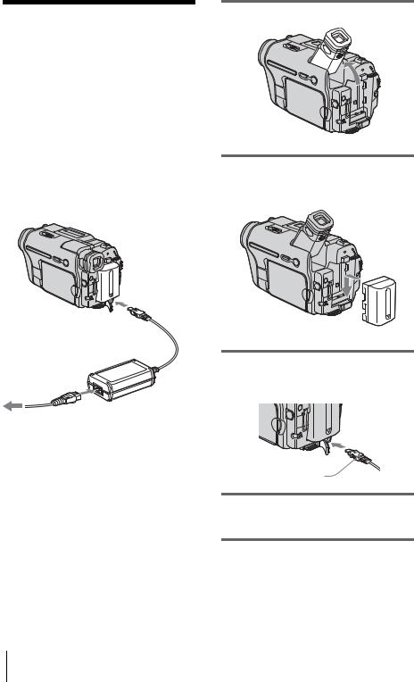
Step 2: Charging the battery pack
You can charge the battery by attaching the
“InfoLITHIUM” battery pack (M series) to your camcorder.
b Notes
•You cannot use batteries other than the “InfoLITHIUM” battery pack (M series) (p. 118).
•Do not short-circuit the DC plug of the AC Adaptor or battery terminals with any metallic objects. This may cause a malfunction.
•Use a nearby wall outlet when using the AC Adaptor. Disconnect the AC Adaptor from the wall outlet immediately if any malfunction occurs.
Battery pack
DC IN jack
DC plug
Power cord
AC Adaptor
To the wall outlet
1 Lift up the viewfinder.
2 Attach the battery pack by sliding it in the direction of the arrow until it clicks.
3 With the v mark on the DC plug facing up, connect the AC Adaptor to the DC IN jack on your camcorder.
v mark
4 Connect the power cord to the AC Adaptor.
5 Connect the power cord to the wall outlet.
14 Getting started
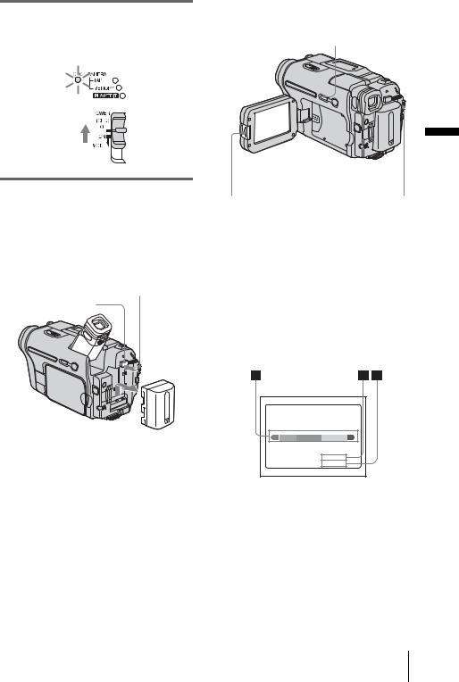
6 Slide the POWER switch up to (CHG) OFF.
The CHG (charge) lamp lights up and charging starts.
After charging the battery
The CHG (charge) lamp turns off when the battery is fully charged. Disconnect the AC Adaptor from the DC IN jack.
To remove the battery pack
POWER switch
BATT(battery) release button
1Set the POWER switch to (CHG) OFF.
2Lift up the viewfinder.
3Slide the battery pack out in the direction of the arrow pressing the BATT (battery) release button down.
b Note
•If you do not use the battery pack for a long time, use up the battery pack completely before storing it. See page 119 about storage of the battery pack.
To check the remaining battery – Battery Info
DSPL/BATT INFO
|
|
Getting |
OPEN |
POWER switch |
started |
|
You can check the battery’s current charge level and its current remaining recording time both during charging or when the power is turned off.
1Set the POWER switch to (CHG) OFF.
2Press OPEN and open the LCD panel.
3Press DSPL/BATT INFO.
The battery information appears for about 7 seconds.
Keep the button pressed to view it for about 20 seconds.
BATTERY INFO
BATTERY CHARGE LEVEL
0% |
50% |
100% |
REC TIME AVAILABLE
LCD SCREEN: 72 min
VIEWFINDER: 95 min
ABattery charge level: Displays approximate remaining amount of power left in the battery pack.
BApproximate possible recording time using the LCD panel.
CApproximate possible recording time using the viewfinder.
,continued
Getting started 15

Charging time
Approximate number of minutes required when you fully charge a fully discharged battery pack at 25°C (77°F). (10 – 30°C (50 – 86°F) recommended.)
Battery pack
NP-FM30 (supplied) |
145 |
|
|
NP-FM50 |
150 |
|
|
NP-QM71/QM71D |
260 |
|
|
NP-QM91/QM91D |
360 |
|
|
Recording time when recording with the LCD screen on
Approximate number of minutes available when you use a fully charged battery pack at 25°C (77°F).
Battery pack |
Continuous |
Typical* |
|
recording |
recording |
|
time |
time |
|
|
|
NP-FM30 |
80 |
40 |
(supplied) |
|
|
|
|
|
NP-FM50 |
130 |
60 |
|
|
|
NP-QM71/ |
315 |
150 |
QM71D |
|
|
|
|
|
NP-QM91/ |
475 |
230 |
QM91D |
|
|
|
|
|
Recording time when recording with the viewfinder
Approximate number of minutes available when you use a fully charged battery pack at 25°C (77°F).
Battery pack |
Continuous |
Typical* |
|
recording |
recording |
|
time |
time |
|
|
|
NP-FM30 |
105 |
50 |
(supplied) |
|
|
|
|
|
NP-FM50 |
170 |
85 |
|
|
|
NP-QM71/ |
415 |
205 |
QM71D |
|
|
|
|
|
NP-QM91/ |
625 |
310 |
QM91D |
|
|
|
|
|
*Approximate number of minutes when recording while you repeatedly record, start/stop, slide the POWER switch to change the power mode, and zoom. The actual battery life may be shorter.
Playing time
Approximate number of minutes available when you use a fully charged battery pack at 25°C (77°F).
This table shows the playing time for tapes recorded in the Digital8  system.
For DCR-TRV460:
The playing time of tapes recorded on other devices in the Hi8 
 /standard 8 mm
  system is reduced by about 20%.
Battery pack |
LCD panel |
LCD panel |
|
opened |
closed |
|
|
|
NP-FM30 |
80 |
120 |
(supplied) |
|
|
|
|
|
NP-FM50 |
135 |
195 |
|
|
|
NP-QM71/ |
335 |
465 |
QM71D |
|
|
|
|
|
NP-QM91/ |
505 |
695 |
QM91D |
|
|
|
|
|
b Notes
•The power will not be supplied from the battery pack when the AC Adaptor is connected to the DC IN jack of your camcorder, even if its power cord is disconnected from the wall outlet.
•The recording and playback time will be shorter when you use your camcorder in low temperature.
•The CHG (charge) lamp flashes during charging, or the battery information will not be correctly displayed in following conditions.
–The battery pack is not attached correctly.
–The battery pack is damaged.
–The battery pack is fully discharged. (For Battery information only.)
16 Getting started
Using an outside power source
You can use the AC Adaptor as the power source when you do not want the battery to run out. While you are using the AC Adaptor, the battery pack will not lose its charge even when it is attached to your camcorder.
PRECAUTION
Even if your camcorder is turned off, AC power (house current) is still supplied to it while connected to the wall outlet via the AC Adaptor.
Connect your camcorder as shown in “Charging the battery pack” (p. 14).
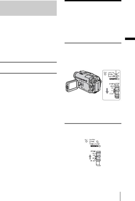
Step 3: Turning the power on
You need to slide the POWER switch repeatedly to select the desired power mode to record or play.
When using this camcorder for the first time, the [CLOCK SET] screen appears (p. 19).
While pressing the green button, slide the POWER switch down.
The power turns on.
To enter the recording or playing mode, slide the switch repeatedly until the respective lamp for the desired power mode lights up.
•CAMERA-TAPE mode: To record on a tape.
•CAMERA-MEMORY mode: To record on a “Memory Stick.”
•PLAY/EDIT mode: To play or edit pictures on a tape or “Memory Stick.”
To turn off the power
Slide the POWER switch up to (CHG) OFF.
started Getting
Getting started 17
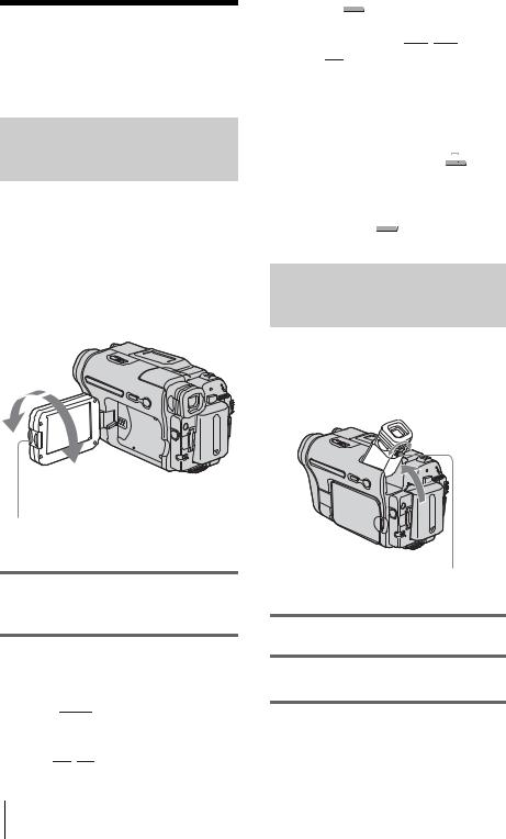
Step 4: Adjusting the LCD panel and viewfinder
Adjusting the LCD panel
You can adjust the angle and brightness of the LCD panel to meet various recording situations.
Even when there are obstructions between you and the subject, you can check the subject on the LCD screen during recording by adjusting the angle of the LCD panel.
Maximum 180 degrees
Maximum 90 degrees
Press OPEN and open the LCD panel.
Open the LCD panel 90 degrees to the camcorder, then rotate it to the desired position.
To adjust the brightness of the LCD screen
1Touch 


 .
.
2Touch [LCD BRIGHT].
If the item is not displayed on the screen, touch 

 /
/ 

 . If you cannot find it, touch
[MENU],  (STANDARD SET) menu, then touch [LCD SET] (p. 78).
3Adjust the item with 

 /
/ 

 , then touch
  .
.
z Tips
•If you rotate the LCD panel 180 degrees to the lens side, you can close the LCD panel with the LCD screen facing out.
•If you are using the battery pack for power source,
you can adjust the brightness by selecting [LCD BL LEVEL] from the [LCD SET] on the  (STANDARD SET) menu (p. 78).
•Even if you adjust the LCD screen backlight, the recorded picture will not be affected.
•You can turn off the operation confirmation beep by setting [BEEP] in the  (STANDARD SET) menu to [OFF] (p. 81).
Adjusting the viewfinder
You can view images using the viewfinder when you close the LCD panel. Use the viewfinder when the battery is running out, or when the screen is hard to see.
Viewfinder lens adjustment lever
1 Lift up the viewfinder.
2 Adjust the viewfinder lens adjustment lever until the picture is clear.
18 Getting started
To use the viewfinder during operation
When you are recording on a tape or a “Memory Stick”, you can adjust the exposure (p. 35) and fader (p. 40) while checking the image on the viewfinder. Have the LCD panel rotated 180 degrees and closed with the screen facing out.
1Set the power mode to CAMERA-TAPE or CAMERA-MEMORY (p. 17).
2Close the LCD panel with the screen
facing out.
 appears on the screen.
3Touch 

 .
.
[Set LCD off?] appears on the screen.
4Touch [YES].
The LCD screen is turned off.
5Touch the LCD screen while checking the display in the viewfinder.
[EXPOSURE], etc. are displayed.
6Touch the button you want to set.
•[EXPOSURE]: Adjust with 

 /
/ 

 and touch

 .
.
•[FADER]: Touch it repeatedly to select a desired effect (only in the CAMERATAPE mode).
•


 : The LCD screen lights up.
To hide the buttons on the LCD screen, touch 

 .
.
Step 5: Setting the date and time
Set the date and time when using this camcorder for the first time. If you do not set the date and time, the [CLOCK SET] screen appears every time you turn on your camcorder.
b Note |
Getting |
|
|
||
• If you do not use your camcorder for about 3 |
|
|
months, the built-in rechargeable button-type |
|
|
battery gets discharged and the date and time |
started |
|
settings may be cleared from the memory. In that |
||
|
||
case, charge the rechargeable button-type battery |
|
|
(p. 123) and then set the date and time again. |
|
OPEN |
|
POWER switch |
|
1 Turn on your camcorder (p. 17).
2 Press OPEN and open the LCD panel.
Proceed to step 7 when you set the clock for the first time.
3 Touch  .
.
60min |
–:––:–– |
||
|
MENU |
EXPO– |
|
|
SURE |
||
|
|
||
1/3 |
FADER |
SPOT |
|
FOCUS |
|||
|
|
||
|
SPOT |
PRGRAM |
|
|
METER |
AE |
|
,continued
Getting started 19

4 Touch [MENU].
60min |
–:––:–– |
|
CAMERA SET |
|
PROGRAM AE |
|
SPOT METER |
|
EXPOSURE |
|
OK |
5 Select |
(TIME/LANGU.) with |
|
/ |
, then touch |
. |
60min |
|
–:––:–– |
|
DISPLAY |
|
|
MENU ROTATE |
|
|
A. SHUT OFF |
|
|
CLOCK SET |
|
|
WORLD TIME |
|
|
LANGUAGE |
OK |
|
PROGRAM AE |
|
|
|
6 Select [CLOCK SET] with 

 /
/ 

 , then touch
  .
.
CLOCK SET |
|
–:––:–– |
||
DATE |
JAN M |
1D |
0: |
00 AM |
2004Y |
||||
|
|
|
|
OK |
7 Set [Y] (year) with  /
/  , then touch


 .
.
CLOCK SET |
|
–:––:–– |
|
DATE |
JAN M |
1D |
0: 00 AM |
2004Y |
|||
|
|
|
OK |
You can set any year up to the year 2079.
8 Set [M] (month), [D] (day), hour and minute in the same way as was done in step 7, then touch  .
.
Step 6: Inserting the recording media
Inserting a cassette tape
You can record on standard 8 mm  , Hi8
, Hi8


 and Digital8
  cassettes in Digital8
  system only. For details on these cassettes (such as write-protection), see page 115.
b Notes
•Do not force the cassette into the compartment. This may cause a malfunction of your camcorder.
•The recording time when you use your camcorder is half of the indicated time on Hi8 


 tape. If you select the LP mode in the menu settings, the recording time is 3/4 of the indicated time on Hi8


 tape.
tape.
1 Slide the  OPEN/EJECT lever in the direction of the arrow and open the lid.
 OPEN/EJECT lever Lid
The cassette compartment automatically comes out and opens up.
20 Getting started
2 Insert a cassette with its window-side facing up.
Window-side
Push the center of the back of the cassette lightly.
3 Press  .
.
The cassette compartment automatically slides back in.
4 Close the lid.
To eject the cassette
1Slide the  OPEN/EJECT lever in the direction of the arrow and open the lid.
The cassette compartment automatically comes out.
2Take out the cassette, then press  .
.
The cassette compartment automatically slides back in.
3Close the lid.
Inserting a “Memory Stick”
For details on the “Memory Stick” (such as write-protection), see page 116.
b Note |
|
|
• When using the half-sized “Memory Stick,” the |
|
|
“Memory Stick Duo,” make sure you attach the |
|
|
Memory Stick Duo adaptor. Your camcorder may |
Getting |
|
malfunction when it is inserted without an adaptor |
||
|
||
(p. 117). |
|
|
Access |
started |
|
lamp |
||
|
b mark
Insert the “Memory Stick” with the b mark at the bottom left corner until it clicks.
To eject a “Memory Stick”
Lightly push the “Memory Stick” in once.
Lightly push in once.
,continued
Getting started 21
b Notes
•If you force the “Memory Stick” into the “Memory Stick” slot in the wrong direction, the “Memory Stick” slot may be damaged.
•Do not insert anything other than a “Memory Stick” into the “Memory Stick” slot. Doing so may cause a malfunction of your camcorder.
•When the access lamp is lit or flashing, your camcorder is reading/writing data from/to the “Memory Stick.” Do not shake or knock your camcorder, turn the power off, eject the “Memory Stick,” or remove the battery pack. Otherwise, image data may be damaged.
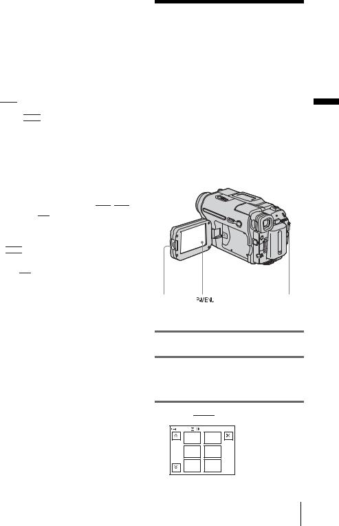
Step 7: Setting the screen language
You can select the language to be used on the LCD screen.
OPEN |
|
POWER switch |
|
1 Turn on your camcorder.
2 Press OPEN to open the LCD panel.
3 Touch 


 .
.
60min |
STBY |
0:00:00 |
|
|
MENU |
EXPO– |
|
|
SURE |
|
|
|
|
|
|
1/3 |
FADER |
SPOT |
|
FOCUS |
|
||
|
|
|
|
|
SPOT |
PRGRAM |
|
|
METER |
AE |
|
4 Touch [LANGUAGE].
If the item is not displayed on the screen, touch 

 /
/ 

 . If you cannot find it, touch [MENU], and select it from the
  (TIME/LANGU.) menu. (p. 82)
60min |
STBY |
0:00:00 |
LANGUAGE: |
ENGLISH |
|
ENG |
ENG |
|
LISH |
[SIMP] |
|
1/2 |
|
|
FRAN |
ESPA |
|
ÇAIS |
ÑOL |
|
22 Getting started
 Loading...