


DCX-D50H
Table of contents
 Loading...
Sony DCX-D50H, DCX-D50PL, DCX-D50L, DCX-D50WSL, DCX-D50WSPL User Manual
...
2003 by Sony Corporation
Operating Instructions
Before operating the unit, please read this manual
thoroughly and retain it for future reference.
3-776-794-11(1)
Color Video Camera
DXC-D50K/D50PK
DXC-D50L/D50PL
DXC-D50WSL/D50WSPL
DXC-D50H/D50PH

2
WARNING
To prevent fire or shock hazard, do not
expose the unit to rain or moisture.
To avoid electrical shock, do not open
the cabinet. Refer servicing to qualified
personnel only.
AVERTISSEMENT
Afin d’éviter tout risque d’incendie ou
d’électrocution, ne pas exposer cet
appareil à la pluie ou à l’humidité.
Afin d’écarter tout risque
d’électrocution, garder le coffret fermé.
Ne confier l’entretien de l’appareil qu’à
un personnel qualifié.
WARNUNG
Um Feuergefahr und die Gefahr eines
elektrischen Schlages zu vermeiden,
darf das Gerät weder Regen noch
Feuchtigkeit ausgesetzt werden.
Um einen elektrischen Schlag zu
vermeiden, darf das Gehäuse nicht
geöffnet werden. Überlassen Sie
Wartungsarbeiten stets nur
qualifiziertem Fachpersonal.
Owner’s Record
The model and serial numbers are located on the top.
Record these numbers in the spaces provided below. Refer
to them whenever you call upon your Sony dealer regarding
this product.
Model No.
Serial No.
CAUTION
Danger of explosion if battery is incorrectly replaced.
Replace only with the same or equivalent type
recommended by the manufacturer. Dispose of used
batteries according to the manufacturer’s instructions.
ATTENTION
Il y a danger d’explosion s’il y a remplacement incorrect de
la batterie. Remplacer uniquement avec une batterie du
même type ou d’un type équivalent recommandé par le
constructeur.
Mettre au rebut les batteries usagées conformément aux
instructions du fabricant.
Vorsicht!
Explosionsgefahr bei unsachgemäßem Austausch der
Batterie. Ersatz nur durch denselben oder einen vom
Hersteller empfohlenen ähnlichen Typ. Entsorgung
gebrauchter Batterien nach Angaben des Herstellers.
PRECAUCIÓN
Peligro de explosión si reemplaza incorrectamente la pila.
Reemplácela por otra igual , u otra de tipo equivalente
recomendada por el fabricante.
Deshágase de las pilas usadas de acuerdo con las
instrucciones del fabricante.
ATTENZIONE
C’è pericolo di esplosione se il blocco batteria viene
sostituito in modo sbagliato.
Sostituire soltanto con lo stesso tipo o uno equivalente
consigliato dal produttore. Smaltire i blocchi batteria
secondo le istruzioni del produttore.
ADVARSEL!
Lithiumbatteri - Eksplosionsfare ved fejlagtig håndtering.
Udskiftning må kun ske med batteri af samme fabrikat og
type.
Levér det brugte batteri tilbage til leverandøren.
ADVARSEL
Eksplosjonsfare ved feilaktig skifte av batteri.
Benytt samme batteritype eller en tilsvarende type anbefalt
av apparatfabrikanten.
Brukte batterier kasseres I henhold til fabrikantens
instruksjoner.
VARNING
Explosionsfare vid felaktigt batteribyte.
Använd samma batterityp eller en ekvivalent typ som
rekommenderas av apparattillverkaren.
Kassera använt batteri enligt fabrikantens instruktion.
VAROITUS
Paristo voi räjähtää jos se on virheellisesti asennettu.
Vaihda paristo ainoastaan laitevalmistajan suosittelemaan
tyypiin.
Hävitä käytetty paristo valmistajan ohjeiden mukaisesti.

3
For customers in the USA
This equipment has been tested and found to comply with the
limits for a Class A digital device, pursuant to Part 15 of the
FCC Rules. These limits are designed to provide reasonable
protection against harmful interference when the equipment
is operated in a commercial environment. This equipment
generates, uses, and can radiate radio frequency energy
and, if not installed and used in accordance with the
instruction manual, may cause harmful interference to radio
communications. Operation of this equipment in a residential
area is likely to cause harmful interference in which case the
user will be required to correct the interference at his own
expense.
You are cautioned that any changes or modifications not
expressly approved in this manual could void your authority
to operate this equipment.
The shielded interface cable recommended in this manual
must be used with this equipment in order to comply with the
limits for a digital device pursuant to Subpart B of Part 15 of
FCC Rules.
For the customers in Europe (for DXC-D50PK/D50PL/
D50WSPL/D50PH)
This product with the CE marking complies with the EMC
Directive (89/336/EEC) issued by the Commission of the
European Community.
Compliance with this directive implies conformity to the
following European standards:
• EN55103-1: Electromagnetic Interference (Emission)
• EN55103-2: Electromagnetic Susceptibility (Immunity)
This product is intended for use in the following
Electromagnetic Environment(s):
E1 (residential), E2 (commercial and light industrial), E3
(urban outdoors) and E4 (controlled EMC environment, ex.
TV studio).
Pour les clients européens (pour les DXC-D50PK/D50PL/
D50WSPL/D50PH)
Ce produit portant la marque CE est conforme à la Directive
sur la compatibilité électromagnétique (EMC) (89/336/CEE)
émise par la Commission de la Communauté Européenne.
La conformité à cette directive implique la conformité aux
normes européennes suivantes:
• EN55103-1: Interférences électromagnétiques (émission)
• EN55103-2: Sensibilité électromagnétique (immunité)
Ce produit est prévu pour être utilisé dans les
environnements électromagnétiques suivants:
E1 (résidentiel), E2 (commercial et industrie légère),
E3 (urbain extérieur) et E4 (environnement EMC contrôlé, ex.
studio de télévision).
Für Kunden in Europa (für DXC-D50PK/D50PL/D50WSPL/
D50PH)
Dieses Produkt besitzt die CE-Kennzeichnung und erfüllt die
EMV-Richtlinie (89/336/EWG) der EG-Kommission.
Angewandter Normen:
• EN55103-1: Elektromagnetische Verträglichkeit
(Störaussendung)
• EN55103-2: Elektromagnetische Verträglichkeit
(Störfestigkeit),
für die folgenden elektromagnetischen Umgebungen:
E1 (Wohnbereich), E2 (kommerzieller und in beschränktem
Maße industrieller Bereich), E3 (Stadtbereich im Freien) und
E4 (kontrollierter EMV-Bereich, z.B. Fernsehstudio).
For the customers in the USA and Canada
RECYCLING NICKEL-CADMIUM BATTERIES
Nickel Cadmium batteries are recyclable.
You can help preserve our environment by
returning your unwanted batteries to your
nearest point for collection, recycling or
proper disposal.
Note: In some areas the disposal of nickel
cadmium batteries in household or
business trash may be prohibited.
RBRC (Rechargeable Battery Recycling Corporation)
advises you about spent battery collection by the following
phone number.
Call toll free number: 1-800-822-8837 (United States and
Canada only)
Caution: Do not handle damaged or leaking nickel-cadmium
batteries.
For safety reasons, be sure to discharge the battery
before discarding it.
Pour les utilisateurs aux Etats-Unis et au Canada
RECYCLAGE DES BATTERIES AU NICKEL-CADMIUM
Les batteries au nickel-cadmium sont
recyclables. Vous pouvez contribuer à
préserver l’environnement en rapportant les
batteries usées dans un point de ramassage,
recyclage ou retraitement.
Remarque: Dans certain pays, il est interdit
de jeter les batteries au nickel-
cadmium avec les ordures
ménagères ou dans les
poubelles de bureau.
Questionnez chez RBRC (Rechargeable Battery Recycling
Corporation) pour les bateries usées.
Le numéro est: 1-800-822-8837 (Etats-Unis et Canada
uniquement)
Avertissement: Ne pas utiliser des batteries au nickel-
cadmium qui sont endommagées ou qui
fuient.
Par mesure de sécurité, déchargez bien la batterie avant
de la jeter.
Gooi de batterij niet weg, maar lever hem in als
KCA.

4 Table of Contents
Table of Contents
Table of Contents
Chapter 1
Overview
Product Configurations ....................................................7
Features .............................................................................9
Features on the DXC-D50/D50P/D50WS/D50WSP .......... 9
Features on the DXC-D50WS/D50WSP........................... 11
Location and Function of Parts .....................................12
Camera Head ..................................................................... 12
VCL-919BY Zoom Lens................................................... 18
DXF-801/801CE V iewfinder ............................................ 20
Chapter 2
Fitting and
Connections
Replacing the Lithium Battery .......................................23
Fitting a VTR ....................................................................25
Using the Camcorder Grip ................................................ 26
Fitting the Lens ...............................................................29
Using Accessories ..........................................................31
Using the Viewfinder......................................................... 31
Using an Optional Microphone ......................................... 32
Fitting to a Tripod.............................................................. 33
Adjusting the Position of the Shoulder Pad ...................... 33
Using the LC-421 Carrying Case ...................................... 34
Connections ....................................................................35
Connecting a Portable VTR .............................................. 35
Connecting a Number of Cameras (Using a Camera
Control Unit) ................................................................ 35
Connecting a Number of Cameras (Without Using a
Camera Control Unit)................................................... 37
Power Supply ..................................................................38
Using Battery Packs .......................................................... 38
Camera Adaptor Power Supply......................................... 39
Memory Stick...................................................................40
Using a Memory Stick....................................................... 40
Notes on Memory Sticks ................................................... 40

Table of Contents 5
Table of Contents
Basic Procedure for Shooting........................................43
Shooting with the DSR-1/1P...........................................46
Using the Edit Search Function While Back Space
Editing .......................................................................... 46
Shuttle shot function.......................................................... 47
Chapter 3
Shooting
Chapter 4
Viewfinder Screen
Indications and
Menus
Viewfinder Screen Indications .......................................49
Changing the Viewfinder Display ..................................... 49
Viewfinder Normal Indications.......................................52
Menu Operation...............................................................55
Displaying the Menus........................................................ 55
Setting the Menus.............................................................. 56
Using the USER Menu ...................................................... 56
OPERATION Menu .......................................................... 60
PAINT Menu ..................................................................... 63
MAINTENANCE Menu ................................................... 66
FILE Menu ........................................................................ 68
Storing and Retrieving a Scene File .................................. 70
Storing to and Retrieving from a Memory Stick............... 71
(Continued)

6 Table of Contents
Table of Contents
Chapter 5
Adjustments and
Settings
White Balance Adjustment .............................................73
Saving an Appropriate White Balance Value in
Memory ........................................................................ 73
Using the Preset White Balance Settings .......................... 75
Light Sources and Color Temperature............................... 76
Using the ATW (Auto Tracing White Balance)
Function........................................................................ 76
Black Balance Adjustment .............................................77
Shutter Settings ..............................................................78
Setting the Clock and Timestamping Recordings .......80
Viewfinder Screen Adjustments ....................................81
Adjusting the Lens..........................................................82
Flange Focal Length Adjustment ...................................... 82
Aperture Adjustments........................................................ 83
Adjusting the Aperture Sensitivity .................................... 84
Macrophotography ............................................................ 85
Settings for Special Cases .............................................86
Skin Detail Correction....................................................... 86
Adjusting Color in the Specified Area .............................. 86
Appendix
Important Notes on Operation .......................................87
Characteristics of CCD Sensors ........................................ 88
Warning Indications........................................................89
Specifications..................................................................90
Related Products................................................................ 91
Chart of Optional Components and Accessories ........93

Chapter 1 Overview 7
Chapter1
Overview
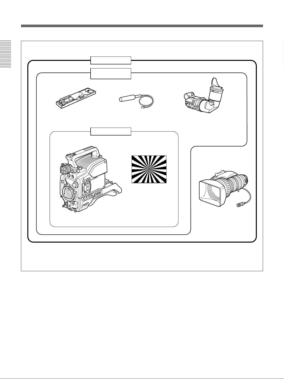
Product Configurations
The eight models, DXC-D50K, DXC-D50L/D50WSL,
DXC-D50H, DXC-D50PK, DXC-D50PL/D50WSPL,
and DXC-D50PH, comprise both NTSC and PAL
versions and the components as shown in the figure on
next page. The operation of the basic camera unit is
the same in all cases.
Chapter 1 Overview
8 Chapter 1 Overview
VCT-U14 Tripod
Adaptor
Microphone
DXF-801/801CE Viewfinder
DXC-D50H/D50PH
Test chart for flange
focal length
adjustment
DXC-D50/D50P/D50WS
a)
/
D50WSP
a)
Camera Head
VCL-919BY
Zoom Lens
DXC-D50K/D50PK
DXC-D50L/D50PL/
D50WSL/D50WSPL
a) The DXC-D50WS/D50WSP camera head has only the
L-model (DXC-D50WSL/D50WSPL) configuration.
Camera adaptor
The product kit does not include a camera adaptor: to
use a camera adaptor, you will need to purchase a
model CA-D50/D50P or CA-TX7/TX7P.
Product Configurations

Chapter 1 Overview
Chapter 1 Overview 9
Features
Features on the DXC-D50/D50P/
D50WS/D50WSP
The DXC-D50WS/S50WSP is a 16:9 wide-screen type
(4:3-16:9 switchable) digital video camera while the
DXC-D50/D50P is a 4:3 standard-screen type digital
video camera. Common features on both types are
described in this section. See also “Features on the
DXC-D50WS/D50WSP” (page 11) for using the
DXC-D50WS/D50WSP.
Newly developed
2
/3-inch IT type Power
HAD (EX) CCD
The DXC-D50/D50P Color Video Camera uses
2
/3-
inch IT type Power HAD CCDs. (For the DXC-
D50WS/D50WSP, Power HAD EX CCDs for wide
screen are used. ) It outperforms most of the exiting
FIT type CCD cameras, in smear, sensitivity, and
signal-to-noise ratio.
•Smear: –140 dB
•Sensitivity: F11.0 (at 3200 K, 2000 lux)
•S/N: 65 dB (NTSC)
63 dB (PAL)
Various image processing
TruEye™ processing makes possible the following
performance features. This digital signal processing
has brought reproduction of natural colors to the level
achieved by the human eye.
Adaptive highlight control
Enables detailed adjustment of contrast control of each
pixel in response to a histogram of luminance signal
levels. This adjustment is automatically optimized for
the desired scene and is effective for shooting a scene
with bright and dark areas.
Knee saturation control
Prevents white breakup when shooting a high intensity
subject, and also prevents color faults in high intensity
subject.
Black gamma control
Enables control of luminance signal levels in black
areas without changing the hue.
Variety of detail corrections
•Skin detail function: this function gives a slightly
softer appearance to the subject’s face. The target
skin color can be easily set with the Menu operation.
•Black halo correction
•Red/green vertical detail correction: this function
performs vertical detail compensation for both red
and green signals.
•Horizontal detail frequency control
Low key saturation
Enables color correction of dark areas where color
reproduction is difficult.
Cross color suppression
The digital 3-line comb filter enables virtual
elimination of frequency elements from the Y/R-Y/
B-Y signals, decreasing the cross color and cross
luminance to the minimum.
Recording and managing scene file data
The DXC-D50/D50P/D50WS/D50WSP is equipped
with the following functions to facilitate camera head
setup.
Scene file system
Using scene files, you can store setting data for up to
20 scenes in the camera.
File operation using a Memory Stick
You can store a scene file into a Memory Stick and
easily retrieve the stored file to reproduce the same
setup conditions. A scene file stored in the Memory
Stick can be retrieved by other DXC-D50/D50P/
D50WS/D50WSP cameras or the RCP-D50/D51
Remote Control Panel to easily share the same setup
among several cameras. It is also possible for a PC
with a slot for a Memory Stick to read scene data and
transfer the data to a camera at a distant location.
Preset matrix
You can quickly make a setup of the camera using
matrix files for factory-preset standard lighting
conditions, such as STD (STANDARD), HI SAT
(HIGH SATURATION), and FL (FLUORESCENT).

Chapter 1 Overview
10 Chapter 1 Overview
Dockable with various types of VTRs
The DXC-D50/D50P/D50WS/D50WSP docks with
the DSR-1/1P DVCAM VTR to configure
a
digital
camcorder. It also docks with the PVV-3/3P Betacam
SP VTR to configure a Betacam SP camcorder.
New Functions boost operability
EZ (easy) mode function
By simply pressing the EZ MODE button, you can
start shooting with the Total Level Control (TLCS)
and Auto Tracing White Balance (ATW) functions
activated with standard camera settings.
EZ (easy) focus
The aperture is automatically adjusted so that the depth
of field becomes shallow for easy focusing. Optimal
exposure is also automatically adjusted.
Programmable gain
The amount of gain relative to the GAIN switch setting
(H, M, or L) can be programmed as –3 dB, 0 dB, 3
dB, 6 dB, 9 dB, 12 dB, 18 dB, 24 dB, 30 dB, and 36
dB.
Auto tracing white balance (ATW)
This function automatically traces the white balance,
which constantly changes as lighting conditions
change. Auto tracing white balance is especially
useful when there is no time to manually adjust the
white balance or when shooting moves between indoor
and outdoor locations.
Dual zebra pattern display
Two types of zebra patterns, zebra 1 and zebra 2 can
be displayed simultaneously or independently in the
viewfinder. The zebra 1 can be set to the levels
ranging from 50 to 109 IRE on the DXC-D50/D50WS
(or from 50 to 109% on the DXC-D50P/D50WSP) and
the zebra 2 indicates the levels of 50 IRE or more for
the DXC-D50/D50WS (or the levels of 50% or more
for the DXC-D50P/D50WSP).
Video monitor output with text
The video signal with text superimposed that is shown
in the viewfinder can also be output to an external
video monitor.
1-kHz audio reference signal output
A 1-kHz audio reference signal can also be output
during color-bar-output mode.
Edit Search Function (when using DSR-1/1P)
When using the DXC-D50/D50P/D50WS/D50WSP
with the DSR-1/1P, pressing the EDIT SEARCH
buttons allow the tape to play back in search mode.
Set either of two playback speeds.
Optical ND filters and electronic CC filters
Ideal light-quantity and color controls are enabled with
the optical ND filters and electronic CC filters. Color
corrections are performed electronically, and the
optical ND filters easily control the depth of field and
the exposure. The electronic CC filters can be
remotely controlled.
Clear scan function
A computer screen can be shot with a minimum of
interference by a horizontal roll and flicker, thanks to
the clear scan function, which enables the shutter
speed to accurately match the scan frequency of the
computer screen. The shutter speed can be varied in
the range of 60.38 to 6,000 Hz.
Other functions
Variable electronic shutter
Monitor output
EVS (Enhanced Vertical-Definition System)
Automatic aperture mode
Low-cut microphone output
Designed for ease of operation
Front-to-back-position adjustable shoulder
pad
The front-to-back position of the shoulder pad can be
adjusted so that the camera is stable on the shoulder.
You can replace the shoulder pad with the flexible
Dynafit Pad designed for the DSR-390/390P and
DSR-570WS/570WSP. For use with the Dynafit Pad,
consult your Sony dealer.
Slide cover
The slide cover can hide the switches and buttons that
are seldom used during shooting.
Features

Chapter 1 Overview
Chapter 1 Overview 11
High-performance viewfinder (DXF-801/
801CE)
•High resolution (600 TV lines of horizontal
resolution)
•Large-diameter eye cup for easier viewing and
focusing
•PEAKING potentiometer for vertical and horizontal
detail control
•Two indicators can be used as TALLY indicators.
•Tough die-cast aluminum body
•DISPLAY switch that can turn the character display
on and off
•Light that can light the lens control elements
•Switching the aspect ratio automatically between
16:9 (wide screen) and 4:3 (standard screen) when
used with the DXC-D50WS/D50WSP
VTR data display
When connected to a VTR, the DXC-D50/D50P/
D50WS/D50WSP is able to display the following data
on the viewfinder screen.
•Time values (counter, time code, or user bit values)
•VTR audio levels
•Remaining tape time
•VTR operation mode
•Remaining battery capacity (when using an Anton
Bauer Intelligent Battery System)
Features on the DXC-D50WS/
D50WSP
Features only on the DXC-D50WS/D50WSP is
described in this section. See “Features on the DXC-
D50/D50P/D50WS/D50WSP” (page 9) for common
features on a 4:3 standard-screen type digital video
camera and 16:9 wide-screen type digital video
camera.
Switchable between 16:9 and 4:3 aspect
ratios
A simple menu operation provides instant switching
between the 16:9 and 4:3 aspect ratios. In 4:3 mode, a
screen equivalent to a 4:3 screen is obtained through
digital processing of the 16:9 video signals produced
by the wide aspect CCD. (See page 67.)
Wide-aspect ID signals
A menu setting is available to add wide-aspect ID
signals
1)
to 16:9-mode video signals.
2)
(See page 67.)
Selection of the safety zone size in 16:9
mode
When the aspect ratio is 16:9, you can change the
safety zone size through menu setting (see page 61.)
..........................................................................................................................................................................................................
1) ID signals complying with EIAJ CPR-1204 (DXC-
D50WS) or complying with ETS WSS (DXC-D50WSP).
2) Video signals refer to the following:
• Video signals output from the VIDEO OUT connector
and MONITOR OUT connector.
• The Y component of Y/C separate signals and the Y
component of component signals output from the VTR
connector.
Chapter 1 Overview
12 Chapter 1 Overview
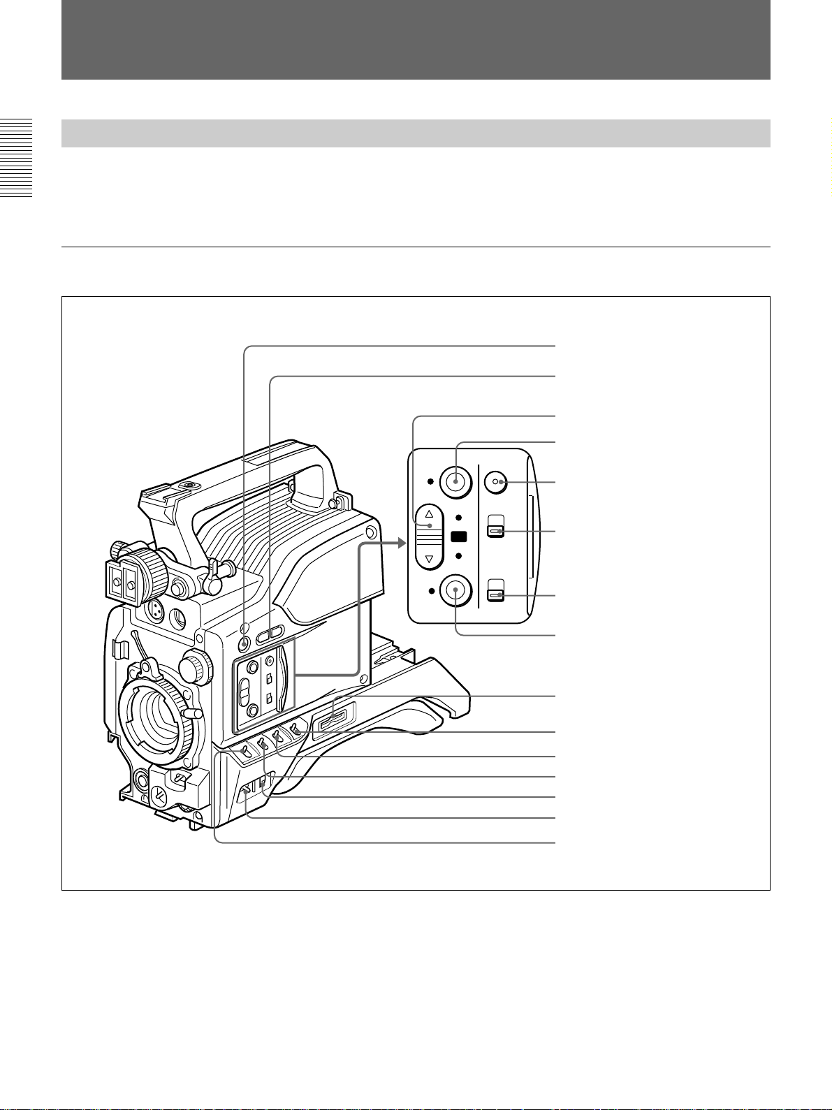
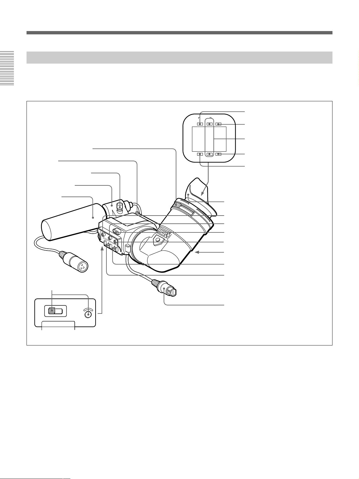
Right side view
Location and Function of Parts
Camera Head
Before attaching/detaching peripheral equipment to/
from the camera head, be sure to turn off the camera.
Otherwise, the camera may not function properly.
EZ
MODE
EZ
FOCUS
ZEBRA
ON
OFF
LOWCUT
MIC
ATW
STD
SPOT
L.
BACK
L.
ON
OFF
qg GAIN switch
1 5600K button
2 EDIT SEARCH buttons
3 A.IRIS MODE switch and indicator
4 EZ MODE button and indicator
5 EZ FOCUS button
6 ZEBRA switch
7 MIC LOW CUT switch
8 ATW button and indicator
9 Memory Stick slot
0 MENU switch
qa W. BAL switch
qs OUTPUT/DCC switch
qd MENU dial
qf POWER switch

Chapter 1 Overview
Chapter 1 Overview 13
1 5600K button
When this button is pressed (lit,) the standard color
temperature for shooting is switched to 5600K. Use
this button for outdoor shooting in daytime or shooting
under lighting with higher color temperature. When
the white balance is adjusted while the Wide Band
White Balance is set, the button may go on or off
automatically.
2 EDIT SEARCH buttons (for operation with
DSR-1/1P)
When using the DSR-1/1P to record, you can see the
search playback while pressing either of these buttons
at recording pause mode to quickly find the next
recording start point. Two playback speeds are
available, and press either of the buttons to the inner
position to increase the speed.
3 A.IRIS (auto aperture) MODE switch and
indicator
When you use the auto aperture function (by setting
the aperture selector on the lens to A), set this switch
to suit the shooting conditions. Selecting BACK L.
gives more light to back-lit subjects, and selecting
SPOT L. adjusts for high contrast in spot-lit subjects.
For normal shooting, set this switch to STD.
4 EZ (“easy”) MODE button and indicator
Depress this button (EZ mode on) when you want to
be able to shoot immediately, with automatic
adjustment of the camera settings to standard values.
When this function is used, the aperture and the white
balance are adjusted automatically. Press this button
again to return the camera to the previous settings (EZ
mode off).
Note
When connecting the CCU-D50/D50P/TX7/TX7P
Camera Control Unit or the RM-M7G Remote Control
Unit, RCP-D50/D51 Remote Control Panel, the “easy
mode” function is disabled.
5 EZ FOCUS button
Press this button to turn the “easy focus” function on.
This opens the aperture, to make it easier to focus
before beginning shooting. The indication “EZ
FOCUS” appears in the viewfinder while the function
is on; to turn it off, press the EZ FOCUS button again.
If left on, the function automatically turns off after
about ten seconds.
Note
If the “easy focus” function is still on when you press
the VTR button, it turns off automatically and
recording starts.
6 ZEBRA switch
Set this switch to the ON position to display a zebra
pattern (diagonal stripes) in the viewfinder.
Depending on the zebra setting on page 9 of the
OPERATION menu (page 61), the zebra 1 for video
levels between 50 to 109 IRE (or 70 to 90%) and the
zebra 2 for video levels 50 to 109 IRE or more (or
100% or more) can be displayed independently or
simultaneously.
7 MIC LOW CUT switch
Set this switch to the ON position to insert a high-pass
filter in the microphone circuit, reducing wind noise.
Normally leave the switch in the OFF position.
8 ATW (auto tracing white balance) button and
indicator
Press this button, turning the indicator on, when you
want the white balance to be adjusted automatically to
follow changes in lighting conditions. (See page 76.)
9 Memory Stick slot
Insert a Memory Stick for storage of file data.
For details, see “Notes on Memory Sticks” on page 40.
0 MENU switch
When you press this switch to the ON/CANCEL
position, the USER menu is displayed. When you
press the switch to the OFF/STATUS position, the
DXC-D50/D50P/D50WS/D50WSP’s status (of current
settings) is displayed.
qa W. BAL (white balance) switch
This selects the white balance setting from the preset
value, the value in memory A or the value in memory
B. (See page 73.)

Chapter 1 Overview
14 Chapter 1 Overview
qs OUTPUT/DCC (Color bar output/dynamic
contrast control) switch
Use this switch to select the DCC function or color
bar output.
Select the CAM/ON position in most cases.
CAM/ON: This activates the DCC function. This
prevents color faults when shooting high-intensity
subjects.
CAM/OFF: When the DCC functions are disabled,
you can manually adjust knee values on page P5
<KNEE/WHITE CLIP> of the PAINT menu. (See
page 64).
BARS: This setting displays color bars.
qd MENU dial
Turn this dial to change menu pages, items, or setting
values, and press it to register.
For details on menu operation, see Chapter 4 “Viewfinder
Screen Indications and Menus” (page 49).
qf POWER switch
This powers the camera on and off. There are two
different ON settings as follows.
ON STBY: This puts the VTR on standby. In this
state, pressing the VTR button on the camera
head, the lens or a camera adaptor starts recording
immediately.
ON SAVE: This puts the VTR in the power-saving
state, with the video head drum stationary. In this
state, it takes a few seconds to start recording after
pressing the VTR button.
Note
The VTR state when this switch is in the ON STBY or
ON SAVE position may depend on the VTR model.
qg GAIN switch
This selects one of the three gain settings, high,
medium or low. You can choose the gain values
assigned to the H, M and L settings from values from
–3 dB to +36 dB. (See page 60.) The factory default
selections are 18 dB (H), 9 dB (M) and 0 dB (L).
Location and Function of Parts
Chapter 1 Overview
Chapter 1 Overview 15
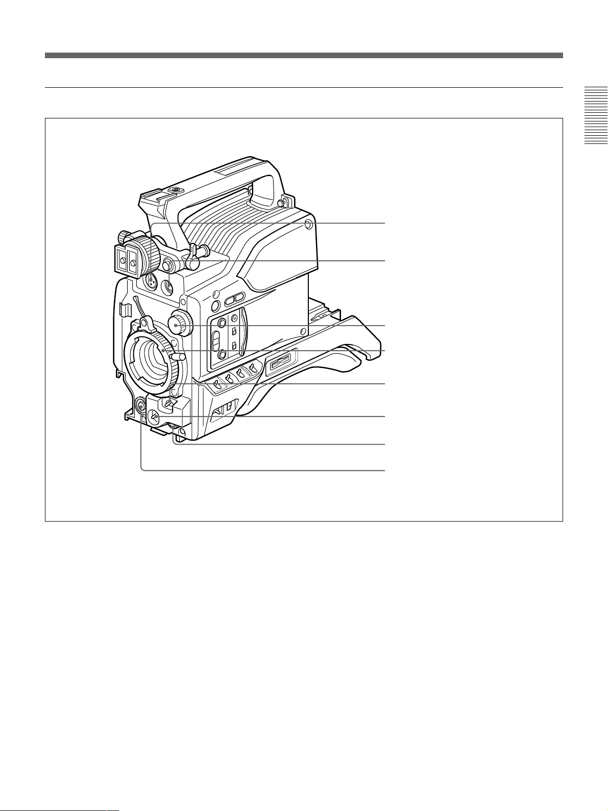
Front view
1 MIC (microphone) IN +48 V connector (XLR 3-
pin, female)
Connect the supplied microphone or an optional
microphone (operable with a +48 V supply).
2 VF (viewfinder) connector (20-pin)
This is the connector for the DXF-801/801CE
viewfinder.
3 FILTER control
Select the ND filter appropriate to the lighting
conditions. (See page 44.)
4 Lens mount
Attach the zoom lens here.
5 SHUTTER switch
Use this switch to turn the shutter on/off, or set the
shutter speed or CLS (clear scan) setting (see page 78).
Usually, set this switch to OFF.
6 WHT/BLK (white balance/black balance) switch
This switch is used for automatic adjustment of the
white balance and black balance. (See pages 73 to 77.)
7 AUDIO LEVEL knob
When the DSR-1/1P is attached, you can use this knob
to manually adjust the channel 1 audio recording level.
8 VTR button
Pressing this button starts and stops recording on the
VTR.
8 VTR button
1 MIC IN +48 V connector
2 VF connector
3 FILTER control
4 Lens mount
5 SHUTTER switch
6 WHT/BLK switch
7 AUDIO LEVEL knob

Chapter 1 Overview
16 Chapter 1 Overview
Left and upper view
1 Fitting for optional microphone holder
You can fit an optional CAC-12 Microphone Holder
here. (See page 32.)
2 Accessory fitting shoe and screw hole
Attach optional video lights or other accessories here.
3 Shoulder strap fixture
To use the shoulder strap supplied with the VTR, fix
one end here and the other end to the VTR.
4 Viewfinder front-to-back position locking lever
Release this lever to adjust the front-to-back position
of the viewfinder. (See page 31.)
5 Viewfinder fitting shoe
Fix the DXF-801/801CE Viewfinder here.
6 Viewfinder left-to-right position fixing ring
Loosen this ring to adjust the left-to-right position of
the viewfinder. (See page 31.)
7 Viewfinder front-to-back position locking knob
Loosen this knob to adjust the front-to-back position of
the viewfinder. (See page 31.)
8 MONITOR OUT connector (BNC)
Outputs both the camera video and the character
information as displayed on the viewfinder screen.
You can connect an optional LCD color monitor to this
connector.
9 VIDEO OUT connector (BNC)
This outputs the video signal captured by the camera.
1 Fitting for optional microphone holder
2 Accessory fitting shoe and screw hole
3 Shoulder strap fixture
4 Viewfinder front-to-back position locking lever
5 Viewfinder fitting shoe
6 Viewfinder left-to-right position fixing ring
7 Viewfinder front-to-back position locking knob
8 MONITOR OUT connector
9 VIDEO OUT connector
0 LENS connector
qa REMOTE connector
qs VTR and camera adaptor connectors
Location and Function of Parts

Chapter 1 Overview
Chapter 1 Overview 17
0 LENS connector (12-pin, for
2
/3-inch lens)
Connect the lens connector.
qa REMOTE connector (10-pin)
Connect the optional RM-M7G Remote Control Unit,
or the RCP-TX7 or RCP-D50/D51 Remote Control
Panel to this connector. Set the CAMERA HEAD
SELECT switch on the bottom of RM-M7G
to 1.
Note
When using a remote control unit or a remote control
panel, note the following points.
•When operating the camera head from the camera
control unit, connect the remote control unit or
remote control panel to the camera control unit.
•EZ mode cannot be used if a remote control unit or a
remote control panel is connected to the camera head.
•Before attaching/detaching the remote control unit or
remote control panel to/from the camera head, be sure
to turn off the camera. Otherwise, the camera may not
function properly.
qs VTR and camera adaptor connectors (PRO 76-
pin DIGITAL and PRO 50-pin)
Connect a dockable VTR or a camera adaptor. A PRO
76-pin DIGITAL connector is for the DSR-1/1P and
the CA-D50/D50P and CA-TX7/TX7P camera
adaptor, and a PRO 50-pin connector is for the PVV-3/
3P.
Chapter 1 Overview
18 Chapter 1 Overview
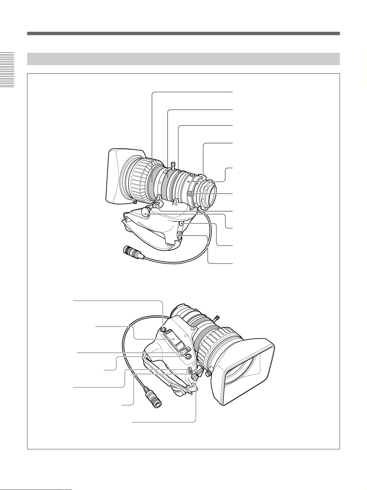
VCL-919BY Zoom Lens
1
2
3
4
5
6
7
8
9
0
1 Focus ring
2 Zoom ring
3 Aperture ring
4 M button
5 F.B adjustment ring and F.B fixing knob
6 MACRO ring
7 ZOOM selector
8 Zoom remote control connector
9 VTR button
0 Shtl button
qa RET button
qs Motorized zoom lever
qd IRIS selector
qf Instant automatic aperture
adjustment button
qg DIP switch
qh Aperture gain adjustment trimmer
Location and Function of Parts
qj Shuttle memory position setting knob

Chapter 1 Overview
Chapter 1 Overview 19
..........................................................................................................................................................................................................
1 Focus ring
Turn this ring to focus the lens on the subject.
2 Zoom ring
For direct manual zoom control, set the ZOOM
selector 7 to the “MANU.” position, and turn this
ring.
3 Aperture ring
For manual aperture control, set the IRIS selector qd to
the “M” position, and turn this ring.
4 M (close-up) button
For close-up work, turn the MACRO ring 6 while
holding this button down. (See page 85.)
5 F.B (flange focal length) adjustment ring and
F.B fixing knob
F.B adjustment ring : To adjust the flange focal
length, loosen the F.B fixing knob, then turn the
ring. (See page 82.)
F.B fixing knob: Fixes the F.B adjustment ring.
6 MACRO (close-up) ring
For close-up, turn this ring while holding the M
button 4 down. (See page 85.)
7 ZOOM selector
This selects the mode of zoom operation.
SERVO: power zoom
MANU. (manual): manual zoom
8 Zoom remote control connector (8-pin)
Connect the optional LO-26 lens remote control unit
for remote control of zooming.
9 VTR button
When operating with a VTR: this button starts and
stops recording, and once more to stop.
When operating with a CCU-D50/D50P Camera
Control Unit connected: pressing this button
connects the return video signal from the camera
control unit to the viewfinder.
(Starting and stopping recording is controlled on
the VTR.)
When operating with a CCU-TX7/TX7P Camera
Control Unit connected: pressing this button
connects the intercom audio signal from the
camera to the camera control unit.
0 Shtl (shuttle shot) button
Use this button for the shuttle shot function.
qa RET (return video) button
This allows you to check the video signal as follows.
When operating with a portable VTR connected
via other equipment: when the VTR is in
recording, pressing this button connects the E-E
video signal
1)
from the VTR to the viewfinder.
When operating with a DSR-1/1P or PVV-3/3P
mounted on the camera head: when the VTR is in
recording pause mode, press this button to review
the last few seconds of the recording in the
viewfinder (recording review).
When operating with a CCU-D50/D50P/
TX7/TX7P Camera Control Unit connected:
pressing this button connects the return video
signal from the camera control unit to the
viewfinder.
When this button is not pressed, the viewfinder
displays the video signal captured by the camera.
qs Motorized zoom lever
Use this to carry out a power zoom. Pressing the lever
harder increases the zoom speed.
W end: zoom toward wide angle
T end: zoom toward telephoto
qd IRIS selector
This selects the mode of aperture operation.
A (automatic): automatic aperture
M (manual): manual aperture
qf Instant automatic aperture adjustment button
While using manual aperture control, press this button
to switch temporarily to the automatic aperture control
setting. The automatic setting is maintained as long as
you hold the button down.
qg DIP switch
The DIP switch for the shuttle shot function. Usually
this switch is covered by a rubber cap.
qh Aperture gain adjustment trimmer
Use this to adjust the aperture gain. Usually the
trimmer is covered by a rubber cap.
qj Shuttle memory position setting knob
Use this button for the shuttle shot function.
1) E-E video signal: “electric-to-electric” video signal.
This is the input video signal which has passed through
internal electrical circuits, but has not been converted to
a magnetic signal.
Chapter 1 Overview
20 Chapter 1 Overview
SHUTTER GAIN UP
TAKE BATTREC
TALLY
HIGH LOW OFF
LIGHT
You can switch the scan size of the DXF-801/801CE
in accordance with the aspect ratio selected on the
camera or camcorder.
1 Eyepiece focusing knob
Turn this to adjust the viewfinder focus to match your
eyesight. (See page 81.)
2 Stopper
Lift up when detaching the viewfinder (See page 31).
3 LIGHT switch and light
The light lights the lens and the switch controls the
light as follows.
HIGH/LOW: Turn the light on and control the
brightness.
OFF: Turns the lights off.
DXF-801/801CE Viewfinder
4 TAKE/TALLY indicator (orange)
This indicator functions as a green tally lamp when the
CCU is connected with this camera.
5 BATT (battery) indicator (red)
This lights when the battery capacity is low.
1 Eyepiece focusing knob
2 Stopper
3 LIGHT switch and light
4 TAKE/TALLY indicator
5 BATT indicator
6 REC/TALLY indicators
7 GAIN UP indicator
8 SHUTTER indicator
9 PEAKING control
0 CONTRAST control
qa Tally lamp
qs BRIGHT control
qd Eyepiece release catch
qf TALLY switch
qg DISPLAY switch
qh Viewfinder connector
Microphone holding screw
Microphone holder
Microphone
Eye cup
Location and Function of Parts

Chapter 1 Overview
Chapter 1 Overview 21
6 REC/TALLY (recording/tally) indicators (red)
•This flashes from the time when you press the VTR
button (8 on page 15 and 9 on page 19) on the lens
or camcorder until recording starts, then stays on
continuously during recording.
•When using a camera control unit, this lights when
the video from the camera is selected.
•This is also used to indicate a fault. (See page 89.)
•The lower indicator can be enabled by menu setting.
(See page 61.)
7 GAIN UP indicator (orange)
This lights when the gain is 3 dB or more.
8 SHUTTER indicator (red)
This lights when the SHUTTER switch (5 on page
15) is in the ON position.
9 PEAKING control
This adjusts the outline intensity of the viewfinder
image. (See page 81.)
0 CONTRAST control
This adjusts the contrast of the viewfinder image. (See
page 81.)
qa Tally lamp
When the TALLY switch qf is in the ON position, this
operates in the same way as the REC/TALLY
indicators 6.
qs BRIGHT (brightness) control
This adjusts the brightness of the viewfinder image.
(See page 81.)
qd Eyepiece release catch
To view the viewfinder screen directly, press this
catch, and hinge up the eyepiece.
qf TALLY switch
Set this switch to the ON position to use the tally lamp
qa.
qg DISPLAY switch
Set this switch to OFF when you want to remove the
character data from the viewfinder and the monitor
connected to the MONITOR OUT connector.
However, items which are set to OFF on page 7 <VF
DISPLAY1> and page 8 <VF DISPLAY2> of the
OPERATION menu are not displayed even when this
switch is set to ON.
Note
If CHARACTER is set to OFF on page 10
<MONITOR OUT> of the OPERATION menu,
character data are not superimposed on the MONITOR
OUT signal even if this switch is set to ON.
qh Viewfinder connector (20-pin)
Connect this to the VF connector (2 on page 15).


Chapter 2 Fitting and Connections 23
Chapter2
Fitting and
Connections
Replacing the Lithium Battery
Notes
•Carefully read the instructions for replacing the
lithium battery. Lithium batteries may explode if
misused.
•Use only CR2032-type lithium batteries. Other types
of lithium batteries may come loose when the
camcorder is moved. If you have difficulty finding
CR2032-type lithium batteries, contact your Sony
dealer.
Before attaching/detaching peripheral equipment to/
from the camera head, be sure to turn off the camera.
Otherwise, the camera may not function properly.
The camera head uses a lithium battery (CR2032) to
retain date and time data.
When the lithium battery’s voltage falls, the clock
indication dose not appear. Replace the lithium battery
and set the clock (see page 80).

Chapter 2 Fitting and Connections
24 Chapter 2 Fitting and Connections
Press down and pull out toward you.
Rear of the
camera head
Battery cover
1 Open the battery cover (on the
rear of the camera head). Pull
the catch of the cover toward
you while pushing it
downward.
For detaching the VTR or camera
adaptor, see “Fitting a VTR” on
the next page.
2 Take out the lithium battery.
3 Reverse step 2 to insert a
replacement lithium battery.
Make sure that the + symbol
on the battery is facing you.
4 Close the battery cover.
Replacing the Lithium Battery
Chapter 2 Fitting and Connections
Chapter 2 Fitting and Connections 25
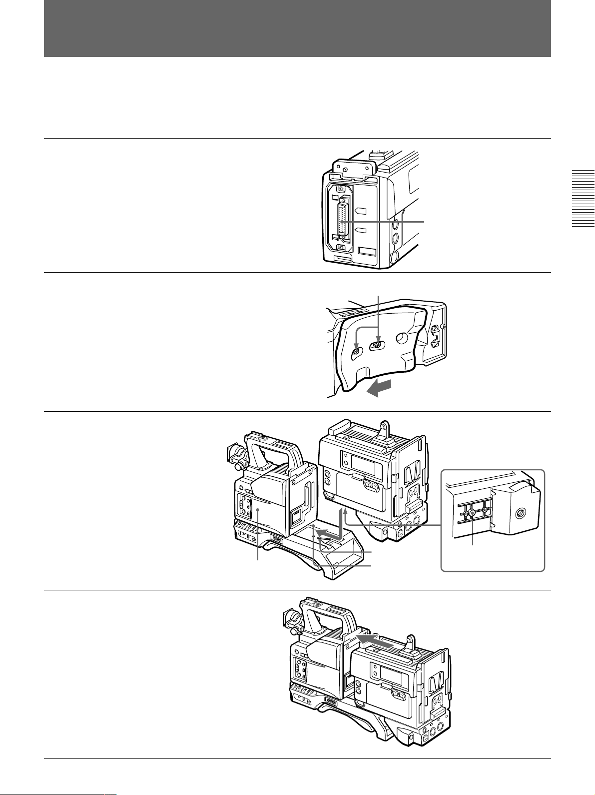
Screws
Fitting a VTR
1 Set the PRO 76-pin DIGITAL
connector on the DSR-1/1P.
(The camera connector on the
PVV-3/3P is PRO 50-pin.)
For details, see the operating
instructions for the DSR-1/1P.
2 Loosen the two screws and
slide the shoulder pad as far as
it will go toward the front.
3 Align the projection on the
bottom of the DSR-1/1P with
the slot on the camera head.
4 Slide the DSR-1/1P and the
camera head together in the
groove as far as possible.
Tighten the two screws in the
grip connector and the two
screws in the shoulder pad
section.
This section explains how to attach the DSR-1/1P to
the camera head. The method for attaching a PVV-3/
3P is similar.
When replacing the camera head grip with a camcorder
grip, see “Using the Camcorder Grip” (page 26).
Camera connector
(PRO 76-pin DIGITAL)
VTR (DSR-1/1P)
Projection
Camera head
Slot
Groove

Chapter 2 Fitting and Connections
26 Chapter 2 Fitting and Connections
Camera head
connection plate
Shoulder strap
fitting
VTR connection
plate
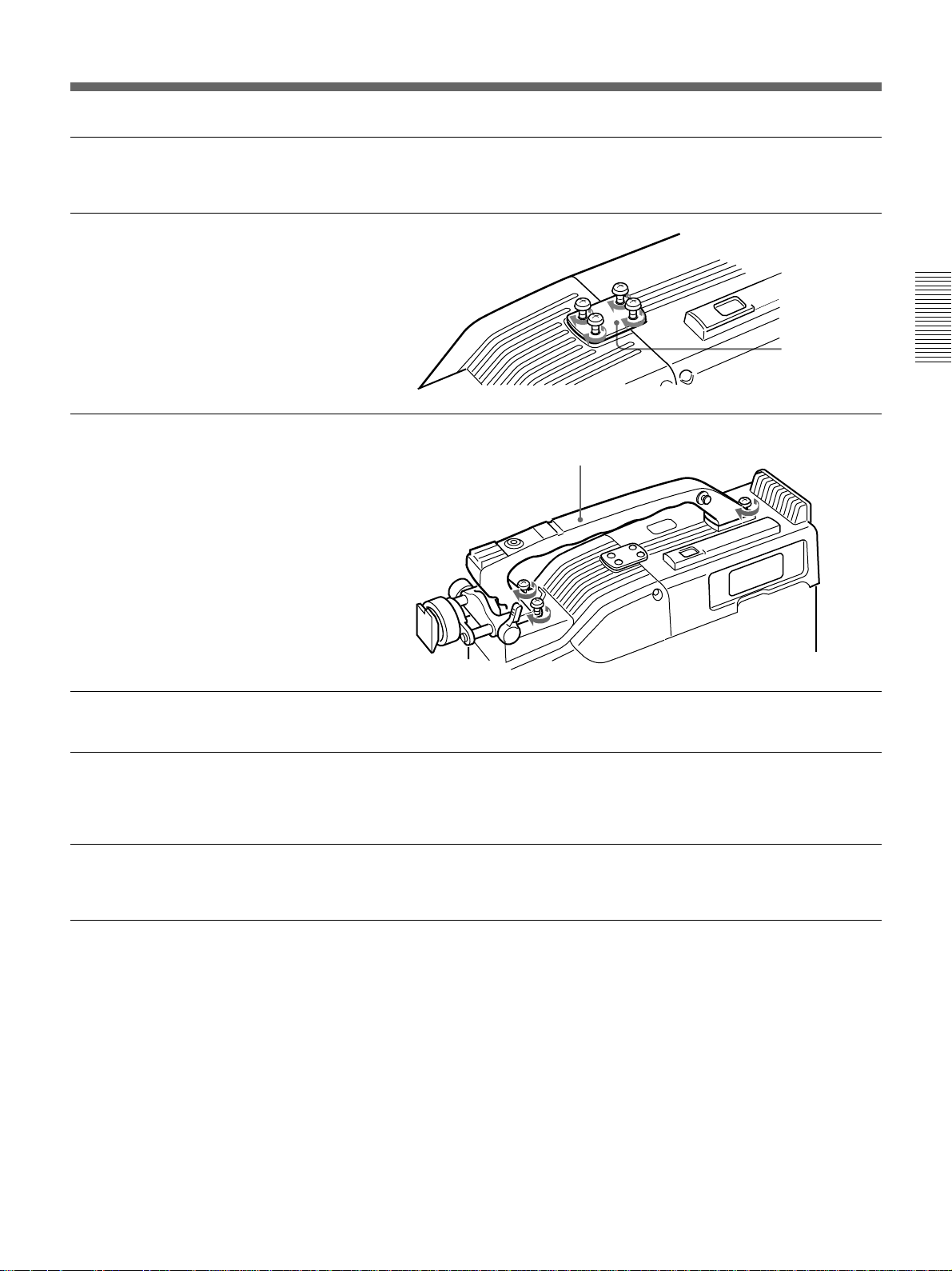
Using the Camcorder Grip
When using the camera head with a VTR as a
camcorder, you can replace the camera head’s grip
with a camcorder grip (not supplied). The type of
camcorder grip and the method for attaching it differ
slightly depending on the type of VTR.
Attaching a camcorder grip to the DSR-1/1P
The CAC-H101 (optional) is required.
1 Adjust the viewfinder to the
full-forward position.
For details, see “Adjusting the
viewfinder position” on page 31.
2 Remove the camera head
grip’s three screws, then pull
up the grip to remove it.
3 Remove the VTR connection
plate.
4 Remove the DSR-1/1P’s
shoulder strap fitting and the
camera head connection plate.
Fitting a VTR
Chapter 2 Fitting and Connections
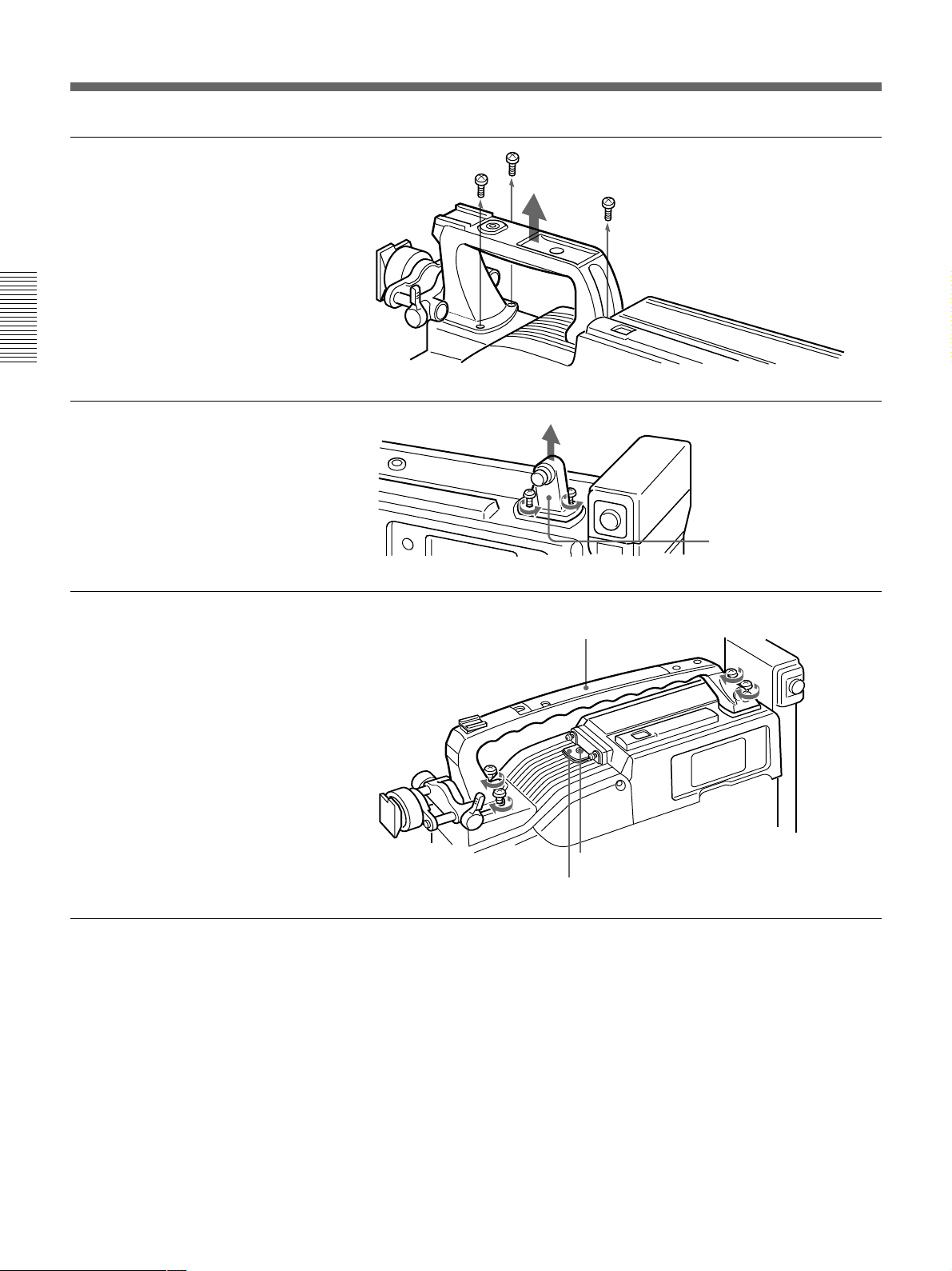
Chapter 2 Fitting and Connections 27
5 Perform the first three steps in
“Fitting a VTR”.
6 Screw the connection plate
(supplied with the grip for the
DVCAM camcorder) which
straddles the connection
between the camera head and
the DSR-1/1P. Also, tighten
the two screws in the shoulder
pad section. (See page 33.)
7 Screw the grip for the
DVCAM camcorder.
Grip for the DVCAM camcorder
Connection
plate
Attaching a camcorder grip to the PVV-3/3P
The CAC-H102 (optional) is required.
1 Perform steps 2 to 4 in “Fitting
a VTR”.
2 Adjust the viewfinder to the
full-forward position.
For details, see “Adjusting the
viewfinder position” on page 31.
Chapter 2 Fitting and Connections
28 Chapter 2 Fitting and Connections
Shoulder strap
fitting
Grip for the Betacam camcorder
3 Remove the grip’s three
screws, then pull up the grip to
remove it.
4 Remove the PVV-3/3P’s
shoulder strap fitting.
5 Attach the cover using the
screw supplied with the CAC-
H102, then screw in to attach
the grip for the Betacam
camcorder.
Screw
Cover
Fitting a VTR
Chapter 2 Fitting and Connections
Chapter 2 Fitting and Connections 29
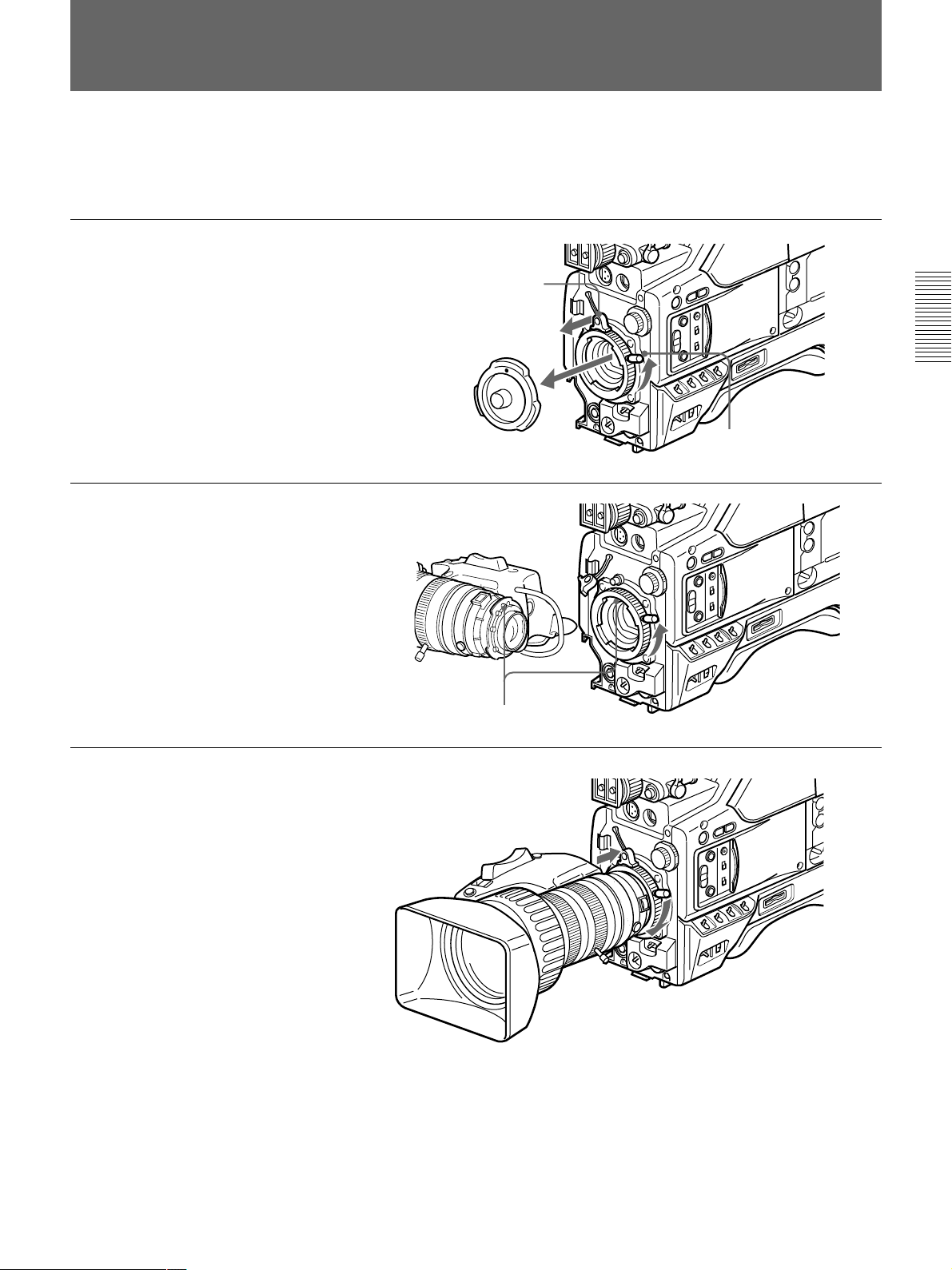
Fitting the Lens
In the case of the DXC-D50K/D50PK model, the lens
is already fitted. In other cases, use the following
procedure to fit the lens.
1 Remove the retaining rubber
which prevents the lens mount
from coming loose, then raise
the lens fixing lever, and
remove the lens mount cap.
2 With the lens fixing lever
turned fully counterclockwise,
push in the lens, aligning the
projection on the lens with the
cutout on the camera.
3 Supporting the lens, turn the
lens fixing lever fully
clockwise. Replace the
retaining rubber on the lens
mount.
Retaining rubber
Lens mount cap
Lens fixing lever
Align and push in.
Loading...