


DFR-E3000
Table of contents
 Loading...
SDDS Recorder System
DIGITAL FILM SOUND CAMERA
DFR-C3000
DIGITAL FILM SOUND ENCODER
DFR-E3000
OPERATION MANUAL
1st Edition
Serial No. 1010 and Higher (DFR-C3000)
Serial No. 1010 and Higher (DFR-E3000)
[English/French/German]

English
WARNING
To prevent fire or shock hazard, do not
expose the unit to rain or moisture.
To avoid electrical shock, do not open the
cabinet. Refer servicing to qualified
personnel only.
This symbol is intended to alert the user to
the presence of important operating and
maintenance (servicing) instructions in the
literature accompanying the appliance.
For the customers in the USA
WARNING:
THIS WARNING IS APPLICABLE FOR USA ONLY.
If used in USA, use the UL LISTED power cord specified
below.
DO NOT USE ANY OTHER POWER CORD.
Plug Cap Parallel blade with ground pin (NEMA 5-15P
Configuration)
Cord Type SJT, three 16 or 18 AWG wires
Length Less than 2.5 m (8 ft 3 in)
Rating Minimum 10 A, 125 V
Using this unit at a voltage other than 120 V may require the
use of a different line cord or attachment plug, or both. To
reduce the risk of fire or electric shock, refer servicing to
qualified service personnel.
This equipment has been tested and found to comply with
the limits for a Class A digital device, pursuant to Part 15 of
the FCC Rules. These limits are designed to provide
reasonable protection against harmful interference when the
equipment is operated in a commercial environment. This
equipment generates, uses, and can radiate radio frequency
energy and, if not installed and used in accordance with the
instruction manual, may cause harmful interference to radio
communications. Operation of this equipment in a residential
area is likely to cause harmful interference in which case the
user will be required to correct the interference at his own
expense.
For customers in the United Kingdom
WARNING
THIS APPARATUS MUST BE EARTHED.
IMPORTANT
The wires in this mains lead are coloured in
accordance with the following code:
Green-and-yellow: Earth
Blue: Neutral
Brown: Live
As the colours of the wires in the mains lead of this
apparatus may not correspond with the coloured markings
identifying the terminals in your plug proceed as follows:
The wire which is coloured green-and-yellow must be
connected to the terminal in the plug which is marked by the
letter E or by the safety earth symbol Y or coloured green or
green-and-yellow.
The wire which is coloured blue must be connected to the
terminal which is marked with the letter N or coloured black.
The wire which is coloured brown must be connected to the
terminal which is marked with the letter L or coloured red.
For the customers in Europe
This product with the CE marking complies with both the
EMC Directive (89/336/EEC) and the Low Voltage Directive
(73/23/EEC) issued by the Commission of the European
Community.
Compliance with these directives implies conformity to the
following European standards:
• EN60950: Product safety
• EN55103-1: Electromagnetic Interference (Emission)
• EN55103-2: Electromagnetic Susceptibility (Immunity)
This product is intended for use in the following
Electromagnetic Environment(s):
E5 (Heavy Industrial)
You are cautioned that any changes or modifications not
expressly approved in this manual could void your authority
to operate this equipment.
The shielded interface cable recommended in this manual
must be used with this equipment in order to comply with the
limits for a digital device pursuant to Subpart B of Part 15 of
FCC Rules.

Table of Contents
English
About the SDDS Recorder System...........................................................2
Principal Features .................................................................................2
System Configuration...........................................................................4
Location of Parts and Controls.............................................................5
Important Precautions...........................................................................8
Loading the Film ..................................................................................8
Specifications .....................................................................................11
Software Operation .................................................................................15
Installing the SDDS Recorder System Software in
Your Computer ........................................................................15
Starting Up the Software ....................................................................16
Record/Setup Menu............................................................................17
Header/Footer Menu...........................................................................22
Density Test Menu .............................................................................25
System Status Menu ...........................................................................27
Maintenance .............................................................................................29
Checking and Cleaning the Principal Parts ........................................29
Periodic Inspections and Maintenance ............................................... 31
Film Production Requirements ..............................................................32
Target Density for Negative Film ......................................................32
Target Density for Positive Film ........................................................ 32
NOTICE FOR USERS
1999 Sony Corporation. All rights reserved. This manual or the software
described herein, in whole or in part, may not be reproduced, translated or
reduced to any machine readable form without prior written approval from Sony
Corporation.
SONY CORPORATION PROVIDES NO WARRANTY WITH REGARD TO THIS
MANUAL, THE SOFTWARE OR OTHER INFORMATION CONTAINED HEREIN
AND HEREBY EXPRESSLY DISCLAIMS ANY IMPLIED WARRANTIES OF
MERCHANTABILITY OR FITNESS FOR ANY PARTICULAR PURPOSE WITH
REGARD TO THIS MANUAL, THE SOFTWARE OR SUCH OTHER
INFORMATION. IN NO EVENT SHALL SONY CORPORATION BE LIABLE
FOR ANY INCIDENTAL, CONSEQUENTIAL OR SPECIAL DAMAGES,
WHETHER BASED ON TORT, CONTRACT, OR OTHERWISE, ARISING OUT
OF OR IN CONNECTION WITH THIS MANUAL, THE SOFTWARE OR OTHER
INFORMATION CONTAINED HEREIN OR THE USE THEREOF.
Sony Corporation reserves the right to make any modification to this manual or
the information contained herein at any time without notice.
The software described herein may also be governed by the terms of a separate
user license agreement.
1(E)

About the SDDS Recorder System
About the SDDS Recorder System
Principal Features
The SDDS1) Recorder System consists of a DFR-C3000 Digital Film
Sound Camera and a DFR-E3000 Digital Film Sound Encoder.
Used in conjunction with a Westrex
Camera, this system records digital and analog audio signals on
undeveloped movie film.
The principal features of this system are as follows:
Eight discrete channels of digital audio signals
A total of eight channels of digital audio signals are recorded on the P
(picture) and S (sound) tracks situated along both sides (edges) of the film.
Digital audio signals recorded on the film
P track C (center)
S track R (right)
L (left)
LC (left center)
SL (surround left)
RC (right center)
SR (surround right)
SW (subwoofer)
2)
RA-1231 Optical Sound Recording
In addition to the above signals, the following signals are recorded on both
tracks as a protective measure against lapses in signal information due to
scratches or stains:
Digital audio signals recorded as auxiliary protection
P track Rmix (mixed R, RC, and SR signals)
S track Lmix (mixed L, LC, and SL signals)
SW’ (compressed SW signal)
C’ (compressed C signal)
Single-medium recording
All digital signals are optically recorded on standard 35-mm film. No
additional media are needed.
Simultaneous recording of analog stereo signals
You can record analog stereo signals at the same time as the digital audio
signals if you use this system in conjunction with a Westrex optical sound
recording camera.
Real-time recording
The DFR-E3000 compresses digital audio data in real time to allow realtime recording.
..........................................................................................................................................................................................................
1) SDDS is a registered trademark of Sony Corporation.
2) Westrex is a registered trademark of Westrex.
2(E)

Easy maintenance
This system uses 64 LEDs for each track as a light source. These LEDs
are grouped into four 16-LED blocks, each of which are separately
replaceable. The blocks are connected to the optical fiber cable via a
newly developed optical connector.
Highly reliable and scratch-free film travel
The sprockets in the DFR-C3000 and the Westrex optical sound recording
camera are connected and synchronized by a belt, and the drum and the
inlet and outlet guides are built to provide the inertia required for stable
film travel. The film guides are provided in the form of rollers that were
specially designed to safeguard the digital and analog audio tracks.
Easy operation
1)
The system software, which runs on an IBM PC/AT
or IBM-compatible
host computer, allows you to set all necessary parameters, and to control
the digital audio recording operations.
Automatic generation of film density test patterns
The DFR-C3000 can generate film density test patterns, the sequence and
duration of which can be set through the system software.
Self-diagnostic functions
This system has various self-diagnostic functions, such as the detection of
low DC voltage, signal checks, fan fault detection, and reel motor
overheating detection. Errors that are detected are displayed on the screen
of the host computer.
Mountable on 19-inch rack
The DFR-E3000 can be mounted on a standard 19-inch rack.
..........................................................................................................................................................................................................
1) IBM PC/AT is a registered trademark of International Business Machines Corporation.
3(E)

About the SDDS Recorder System
System Configuration
To Westrex Camera System
REMOTE
REF
VIDEO
CAMERA
I/O
TIMECODE IN
DFR-C3000 Digital Film Sound
Camera
FS OUT
ENCODER OUT
CAMERA IN
ANALOG OUT
ENCODER IN
SYNC
DFR-E3000 Digital Film Sound Encoder
CAMERA OUT
AUDIO IN
SDIF2, AES/
EBU or
analog signal
ADVANTEST
TQ82017 Optical
Power Probe
(optional)
PC I/F
(IEEE1284)
D3000 I/F
1)
RS232C GPIB
COM
LPT
ADVANTEST
TQ8215/TQ13216
Optical Power
Multimeter
(optional)
GPIB
IBM PC/AT or
compatible computer
with a GP-IB interface
card (controller,
optional)
TIMECODE OUT
Digital or analog 8-channel audio
reproducer (optional)
Reference video signal
(NTSC, MONO, or PAL)
AUDIO OUT
FS IN
To a monitor amplifier
DFP-D3000 Digital Film Sound
Decoder (optional)
To a monitor amplifier
..........................................................................................................................................................................................................
1) ADVANTEST is a registered trademark of ADVANTEST CORPORATION.
4(E)
Eight channels of audio signals in analog, SDIF-2, or AES/EBU format,
played back on a digital or analog audio reproducer, are input to the DFRE3000, which then compresses the signals and generates mixed signals as
a protective measure for signal dropout.
The DFR-E3000 then processes the signals for recording onto the film and
sends the processed signals to a DFR-C3000 which is also connected to the
host computer.
Under the control of the DFR-E3000, the DFR-C3000 records the digital
audio signals to the film.
Location of Parts and Controls
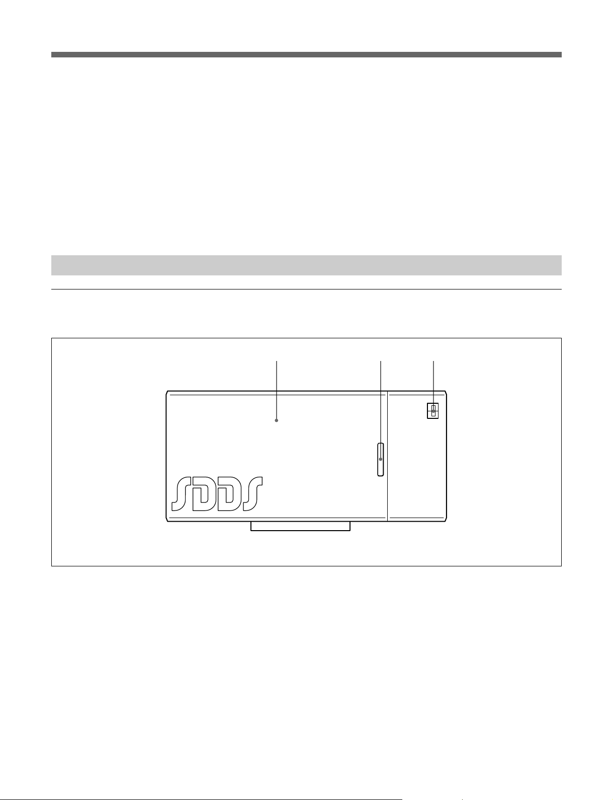
DFR-C3000
Front view
Door
Front view of the DFR-C3000
Door pull
POWER switch
5(E)
About the SDDS Recorder System
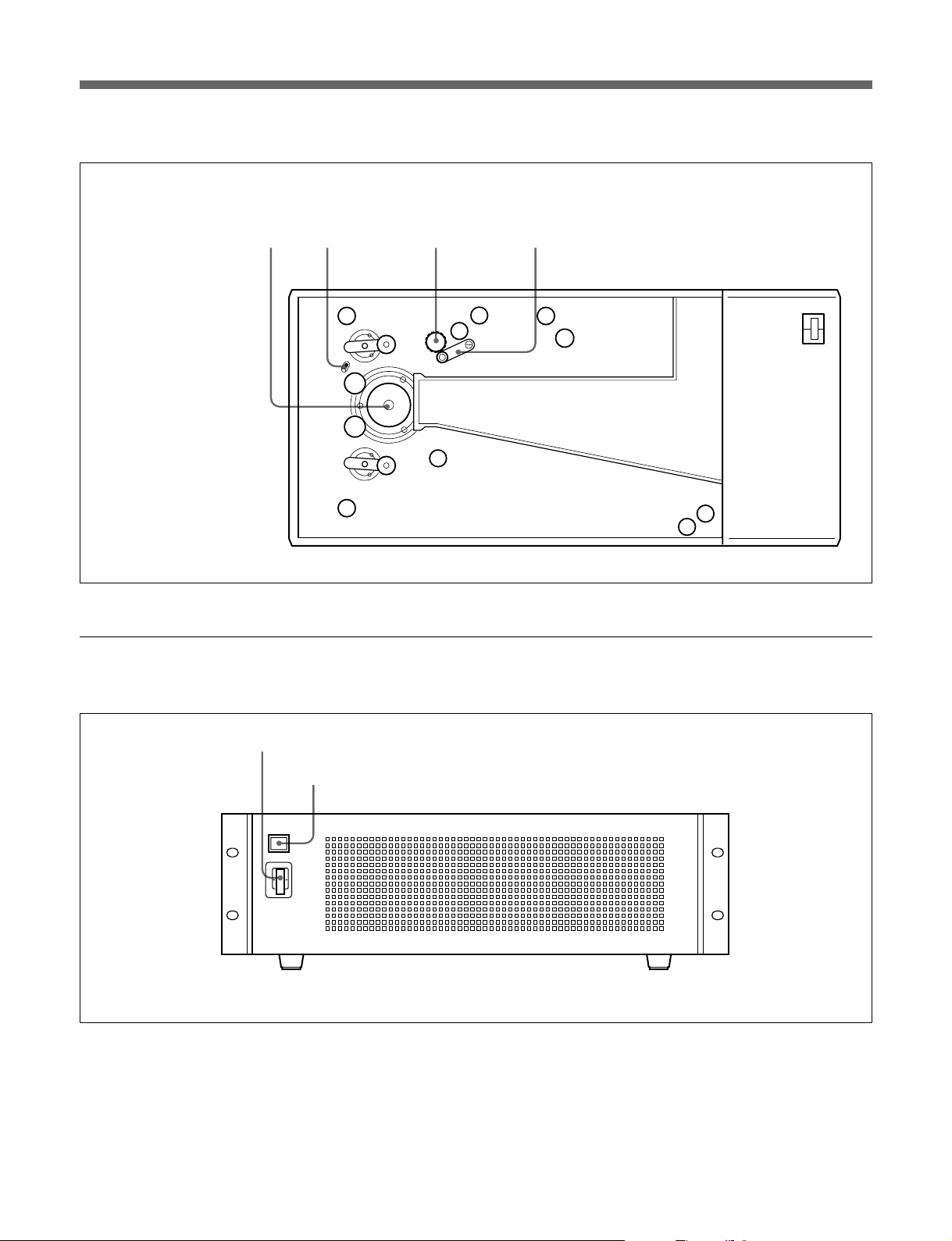
Internal view
DFR-E3000
Drum Tension indicator Sprocket wheel
Internal view of the DFR-C3000
Pressure arm
Front view
1 POWER switch
Turns the power on or off.
1 POWER switch
2 Power and status indicator
Front view of the DFR-E3000
2 Power and status indicator
Lights up orange when the encoder is in standby mode
and light up green when the power is turned on.
The indicator changes to red and flashes when an
internal error has been detected and needs repair.
6(E)
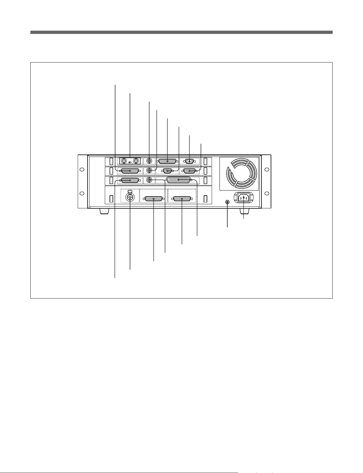
Rear view
1 CAMERA OUT connector
2 REFERENCE connectors and 75Ω termination switch
3 VIDEO SYNC OUT connector
4 CAMERA SYNC connector
5 PC I/F (IEEE 1284) connector
6 CAMERA IN connector
7 DFP-D3000 I/F connector
8 REMOTE I/O connector
- AC IN
U
9 AC IN connector
q; U (ground) connector
qa SDIF-2 IN connector
qs ANALOG OUT connector
qd WORD SYNC connector
qf ANALOG IN connector
qg TIME CODE connector
qh AES/EBU IN connector
Rear view of the DFR-E3000
1 CAMERA OUT connector
Connect to the DFR-C3000 for recording.
2 REFERENCE connectors and 75Ω termination
switch
Input video reference signal. Set the 75Ω termination
switch to OFF if you are using a loop-through
connection; set it to ON if you are not using a loopthrough connection.
3 VIDEO SYNC OUT connector
Outputs sync signal to external equipment. The type
of the output sync signal can be selected using the
computer connected to the PC I/F connector (NTSC,
MONO, or PAL). For details, contact your nearest
Sony dealer or service personnel.
4 CAMERA SYNC connector
Connect to the Westrex Camera System to output sync
signal. For details, contact your nearest Sony dealer or
service personnel.
5 PC I/F (IEEE 1284) connector
Connect to the IBM PC or compatible personal
computer for controlling the system. For details,
contact your nearest Sony dealer or service personnel.
6 CAMERA IN connector
Connect to the DFR-C3000 to input the sync signal.
7 DFP-D3000 I/F connector
Connect to the DFP-D3000 for monitoring the
recording.
7(E)

About the SDDS Recorder System
8 REMOTE I/O connector
Connect to the Westrex Camera System to output start
or stop command. For details, contact your nearest
Sony dealer or service personnel.
9 AC IN connector
Connect the AC power cord. For information on the
type of the AC power cord to be used, contact your
nearest Sony dealer or service personnel.
q; U (ground) connector
Used to ground the DFR-E3000.
qa SDIF-2 IN connector
Connect to the digital audio reproducer to input 8channel (8 lines) balanced SDIF-2 digital audio signal.
Important Precautions
qs ANALOG OUT connector
Connect to the monitor amplifier to output 8-channel
balanced analog audio signal.
qd WORD SYNC connector
Connect to the digital audio reproducer to output word
sync signal.
qf ANALOG IN connector
Connect to the analog audio reproducer to input 8channel balanced analog audio signal.
qg TIME CODE connector
Input time code for easy management of the recording
time.
qh AES/EBU IN connector
Connect to the digital audio reproducer to input 8channel (8 lines) balanced AES/EBU digital audio
signal.
Loading the Film
•If your AC power supply is lower than 100 V or higher than 240 V,
contact the dealer from whom you purchased the system or service
personnel.
•Do not open the door of the DFR-C3000 or touch the belt while the film
is transporting.
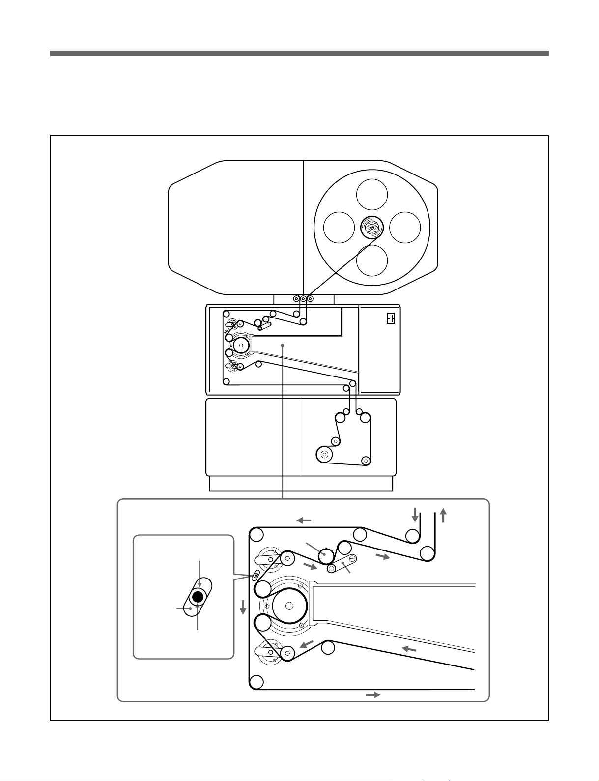
Do the following procedure to load the film into the recorder:
1 Set the film magazine loaded with undeveloped film on the DFR-
C3000 and attach the belt behind the magazine.
2 Remove the T-reel side lid of the film magazine, open the door of the
Westrex RA-1231 Optical Sound Recording Camera, and then open
the door of the DFR-C3000 (in this order).
3 Pull out several feet of film from the S-reel and thread the film up to
the T-reel (the film should follow path indicated by the blue line inside
the DFR-C3000).
8(E)
When threading the film onto the sprocket, turn the pressure arm
counterclockwise to allow the film to wind around the sprocket.
4 Make sure that the indicator link hole can be seen at the center of the
panel hole and that the tension indicator can be seen in the indicator
link hole. If not, adjust the film by one, two, or three sprockets.
Verify that the indicator link hole is positioned in the center of the
panel hole and that the tension indicator is positioned in the center of
the indicator link hole. If not, turn the sprocket to advance the film
until it does.
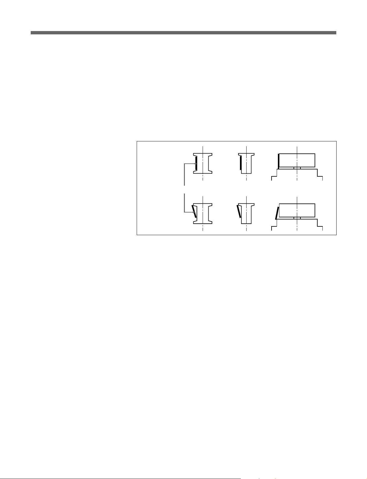
5 Make sure the film is threaded correctly along the entire film path, and
that at no point does the film jut beyond the flange of any guide or
drum.
Correct:
Film
Incorrect:
9(E)
About the SDDS Recorder System
6 Replace the T-reel side lid of the film magazine, close the door of the
DFR-C3000, and then close the door of the Westrex camera (in this
order).
Film magazine
S-reel T-reel
DFR-C3000 Digital
Film Sound Camera
Westrex RA-1231 Optical
Sound Recording
Camera
Indicator link holes
Panel hole
Sprocket wheel
Pressure arm
10(E)
Tension indicator
Loading the film

Specifications
SDDS Digital Audio Signals
Number of channels 8
Channel assignment Channel 1: Left
Sampling frequency 44.1 kHz
Frequency response 20 Hz to 20 kHz ±1.0 dB
Dynamic range 90 dB or more
Distortion 0.07% or less
Crosstalk –80 dB or less
Headroom 20 dB
DFR-C3000 Digital Film Sound Camera
Channel 2: Left Center
Channel 3: Center
Channel 4: Right Center
Channel 5: Right
Channel 6: Boom
Channel 7: Surround Left
Channel 8: Surround Right
Power requirements 100-240 V AC, 50/60 Hz
Power consumption 200 VA
Operating temperature 20°C to 30°C (68°F to 86°F)
Operating humidity 20% to 80% relative humidity
Storage temperature –20°C to +60°C (–4°F to +140°F)
Mass 45 kg (99 lb 3 oz)
Dimensions (w/h/d) 615 × 275 × 350 mm
1
/4 × 107/8 × 137/8 inches)
(24
Peak inrush current (1)Power ON, current probe method: 50 A (240
V), 20 A (100 V)
(2)Hot switching inrush current, measured in
accordance with European standard EN55103-
1: 10 A (230 V)
Lock-in time 10 sec or less at normal speed
Film negative Red sensitive sound negative (Kodak
1)
or equivalent recommended)
2374
Film magazine capacity
610 m (2000 feet) max.
Start speed Slow motor start to avoid film damage
..........................................................................................................................................................................................................
1) 2374 is a registered trademark of Eastman Kodak Company.
11(E)

About the SDDS Recorder System
DFR-E3000 Digital Film Sound Encoder
Power requirements 100-240 V AC, 50/60 Hz
Power consumption 200 VA
Operating temperature 5°C to 40°C (41°F to 104°F)
Operating humidity 10% to 90% relative humidity
Storage temperature –20°C to +60°C (–4°F to +140°F)
Mass 13 kg (28 lb 11 oz)
Dimensions (w/h/d) 424 × 132 × 451 mm
Peak inrush current (1)Power ON, current probe method: 25 A (240
Input and output connector characteristics
3
/4 × 51/4 × 177/8 inches)
(16
V), 10 A (100 V)
(2)Hot switching inrush current, measured in
accordance with European standard EN55103-
1: 7 A (230 V)
Audio input/output
AES/EBU IN D-sub, 25-pin female
Sampling frequency: 44.056 kHz/44.1 kHz/
48 kHz (selectable by PC) (Includes sampling rate
converter)
Headroom: 20 dB/18 dB/16 dB (selectable by
PC)
Input audio format: AES/EBU (selectable by PC)
SDIF-2 IN D-sub, 50-pin male
Sampling frequency: 44.056 kHz/44.1 kHz/
48 kHz (selectable by PC) (Includes sampling rate
converter)
Headroom: 20 dB/18 dB/16 dB (selectable by
PC)
Input audio format: SDIF-2 (selectable by PC)
AUDIO IN D-sub, 25-pin female
Reference level: +4 dBu/0 dBu/–10 dBu
(selectable by PC)
Impedance: 10 kΩ minimum
Sampling frequency: 44.1 kHz
Frequency response: 20 Hz to 20 kHz ±1 dB
Dynamic range: 90 dB or more
Distortion: 0.07% or less
Crosstalk: –80 dB or less
Input signal: analog audio
12(E)

AUDIO OUT D-sub, 25-pin male
Reference level: +4 dBu/0 dBu/–10 dBu
(selectable by PC)
Load impedance: 600 Ω
Sampling frequency: 44.1 kHz
Frequency response: 20 Hz to 20 kHz ±1 dB
Dynamic range: 90 dB or more
Distortion: 0.07% or less
Crosstalk: –80 dB or less
Output signal: analog audio
Reference
REFERENCE BNC-type ×2, loop-through
Impedance: 75 Ω (75Ω termination switch
attached)
Signal format: black burst or composite sync
Video system: NTSC, MONO, or PAL (auto
detection)
VIDEO SYNC OUT BNC-type
Impedance: 75 Ω
Signal format: composite sync
Video system: NTSC, MONO, or PAL (selectable
by PC)
CAMERA SYNC BNC-type
Impedance: 75 Ω (4 Vp-p)
Signal format: composite sync
Video system: MONO
WORD SYNC BNC-type
Impedance: 75 Ω
Level: TTL
Frequency: 44.056 kHz/44.1 kHz/48 kHz
(selectable by PC)
DFR-C3000 input/output
CAMERA OUT D-sub, 25-pin female
SDDS Camera data interface
CAMERA IN D-sub, 9-pin female
SDDS Camera control interface
Control
REMOTE I/O D-sub, 15-pin male
Optical isolated input and output
Output: 4 (motor start, motor stop, and two spare)
Input: 3 (spare)
TIME CODE XLR-type, female
Impedance: 10 kΩ or more
Signal format: SMPTE/EBU (auto detection)
PC I/F (IEEE1284) D-sub, 25-pin female
IEEE1284-EPP compatible
13(E)

About the SDDS Recorder System
Others
DFP-D3000 I/F 5W1 connector
Accessories supplied
Operation Manual (1)
Rack mount adaptors (1 set)
Westrex modification kit (1)
Required customer supplied equipment
Westrex RA-1231 Optical Sound Recording Camera and its peripheral
devices (1 set)
IBM PC/AT or compatible personal computer (1) (For details, see page
15.)
Digital or analog 8-channel audio reproducer (1)
Macbeth
Negative film QC system (modified DFP-R2000 and DFP-D2000)
1)
Signal format: SDDS serial interface
TD903 optical measurement equipment (1 set)
Optional equipment
DFP-D3000 SDDS Decoder (1)
8-channel monitor amplifier (1)
ADVANTEST TQ8215/13216 Optical Power Multimeter (1)
ADVANTEST TQ82017 Optical Sensor (1)
Optical sensor block (1)
Design and specifications are subject to change without notice.
..........................................................................................................................................................................................................
1) Macbeth is a registered trademark of Kollmorgen Corporation.
14(E)

Software Operation
Installing the SDDS Recorder System Software in Your Computer
Recommended minimum hardware configuration
The recommended minimum hardware configuration of your IBM PC/AT
or IBM-compatible personal computer is as follows:
1)
CPU: MMX Pentium
Memory: 64 megabytes or more
Display: 800 × 600 high color or more
Free space on the hard disk:
10 megabytes or more
CD-ROM drive: One or more
Floppy disk drive: At least one drive (2DD/2HD)
RS-232C port (COM port):
D-sub, 9-pin male
LPT port: D-sub, 25-pin female supporting IEEE-1284 EPP
OS: Microsoft Windows 95 or Microsoft Windows
2)
98
266 MHz or higher
GP-IB unit and software (for LED optical power adjustment)
GP-IB interface: AT-GPIB
GP-IB driver: NI-488.2
3)
or PCMCIA-GPIB
3)
software for Microsoft Windows 95 or
3)
Microsoft Windows 98, version 1.50
(These products are manufactured by National Instruments Corporation.)
Before installation
•Check the COM port and LPT port settings.
COM port: IRQ4, I/O PORT 3F8h, COM1
LPT port: IRQ7, I/O PORT 378h, EPP mode, LPT1
To use other settings, contact your nearest Sony dealer or service
personnel.
•Make sure the following:
— COM1 and LPT1 ports are set to enable.
— LPT1 is set to EPP.
— The resources of COM1 and LPT1 do not conflict with other devices.
If these conditions are not met, recording error may result.
To check the COM port and LPT port settings
Use BIOS setup. For details, refer to the operating instructions supplied
with your personal computer or contact the manufacturer of the computer.
..........................................................................................................................................................................................................
1) MMX Pentium is a trademark of Intel Corporation.
2) Microsoft Windows 95 and Microsoft Windows 98 are trademarks of Microsoft Corporation.
3) AT-GPIB, NI-488.2, and PCMCIA-GPIB are registered trademarks of National Instruments Corporation.
15(E)

Software Operation
To check the resource conflict
Point to Start, then Setup, and then point to Control Panel. Double-click
the System in the Panel window, then click the Device Manager tab.
!
Check that the LPT1 and COM1 are effective and no
!
displayed. When
conflict with other devices. In this case, resolve the conflict. For details,
refer to the help of Windows 95/98 or contact the manufacturer of the
computer or Microsoft Corporation.
Software installation
Before the installation of the software, be sure to connect all the
components and turn them on for the personal computer to check the
connection and obtain information of the connected components.
is displayed, the resources of COM1 and LPT1 may
mark is
1 Turn off all the components to be connected.
2 Connect the DFR-E3000 to the LPT1 port of the computer using the
IEEE 1284 cable and DFR-C3000 to the COM1 port of the computer
using the RS-232C cross cable, respectively.
Starting Up the Software
3 Turn on all the components and start up the Windows 95/98.
4 Insert the DFR-3000 SDDS RECORDER CONTROL SOFTWARE
CD-ROM in the CD-ROM drive.
The installation program starts up automatically. If it does not, point
to Start, point to the installation program, and then select “Run....,” and
type “D:¥setup” into the dialog box (when the CD-ROM drive is drive
D) and press the Enter key or click the OK button.
5 Continue installation by following the instructions on the display.
Turn on all the components and start the Windows 95/98, Point to Start,
then Program, and then click DFR3000 SDDS RECORDER.
Record/Setup menu appears. If the menu does not appear, check the
connection of all the components and that the installation of the software
has been successful.
Click on the menu bar to access any of the menu items.
16(E)
Menu bar
Record/Setup
•Click to display Record/Setup menu.
•Sets the input/output signals and recording parameters.
•Starts and stops the recording operation.
Header/Footer
•Click to display Header/Footer menu.
•Defines the pattern of the film header and footer and sets the density
patch.
Density Test
•Click to display Density Test menu.
•Used to create a density test film for finding the optimum LED power
setting.
System Status
•Click to display System Status menu.
•Used to display system error indication, serial number, and hours meter
of the DFR-C3000.
Help
Open the help of this software.
System Condition
•Click to display System Condition menu.
•If an error occurs in the system, The “OK” indication in this box changes
to “NG.”
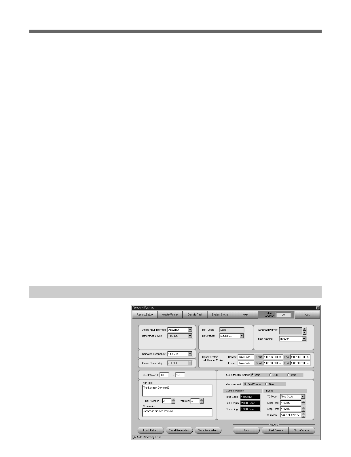
Record/Setup Menu
Quit
Click to exit the software. When you click this button, a message
confirming the exit appears. Click “Yes” to quit this software.
Status line
This is located at the bottom of the each menu screen to indicate progress
of the recording, guide of the value to be entered, etc.
17(E)

Software Operation
Audio Input Interface box
Specifies audio signal to be recorded. Select AES/EBU, SDIF-2, or
Analog in accordance with the format of the digital audio signal input to
the DFR-E3000.
Reference Level box
Selects the reference level of the audio signal to be recorded.
Select the appropriate reference level in the Reference Level box.
Sampling Frequency box
When AES/EBU or SDIF-2 is selected in the Audio Input Interface box,
sampling frequency can be selected among 44.056 kHz, 44.1 kHz, and 48
kHz. Since the SDDS format uses sampling frequency of 44.1 kHz, the
internal sampling rate converter converts the input signal when 44.056 kHz
or 48 kHz has been selected.
Player Speed Adj. box
When AES/EBU or SDIF-2 is selected in the Audio Input Interface box,
adjust the sampling frequency using this item. For details, contact your
nearest Sony dealer or service personnel.
Ref. Lock box
“Lock” appears when the whole system is operating in sync.
Reference box
Specifies the sync signal to use and selects the format of the signal output
to the VIDEO SYNC OUT connector.
Selected sync signal Signal input from the
REFERENCE connector
Ext. NTSC NTSC NTSC
Ext. MONO MONO MONO
Ext. PAL PAL PAL
Int. NTSC — NTSC
Int. MONO — MONO
Int. PAL — PAL
Signal output to the
VIDEO SYNC OUT
connector
Frequency of vertical sync signal in each video system is as follows:
Video system Frequency of vertical sync signal
NTSC 59.94 Hz
MONO 60 Hz
PAL 50 Hz
18(E)
Additional Pattern box
Displays the additional pattern to the visual character of the Header/Footer
setting. For details on creation and use of additional patterns, contact your
nearest Sony dealer or service personnel.
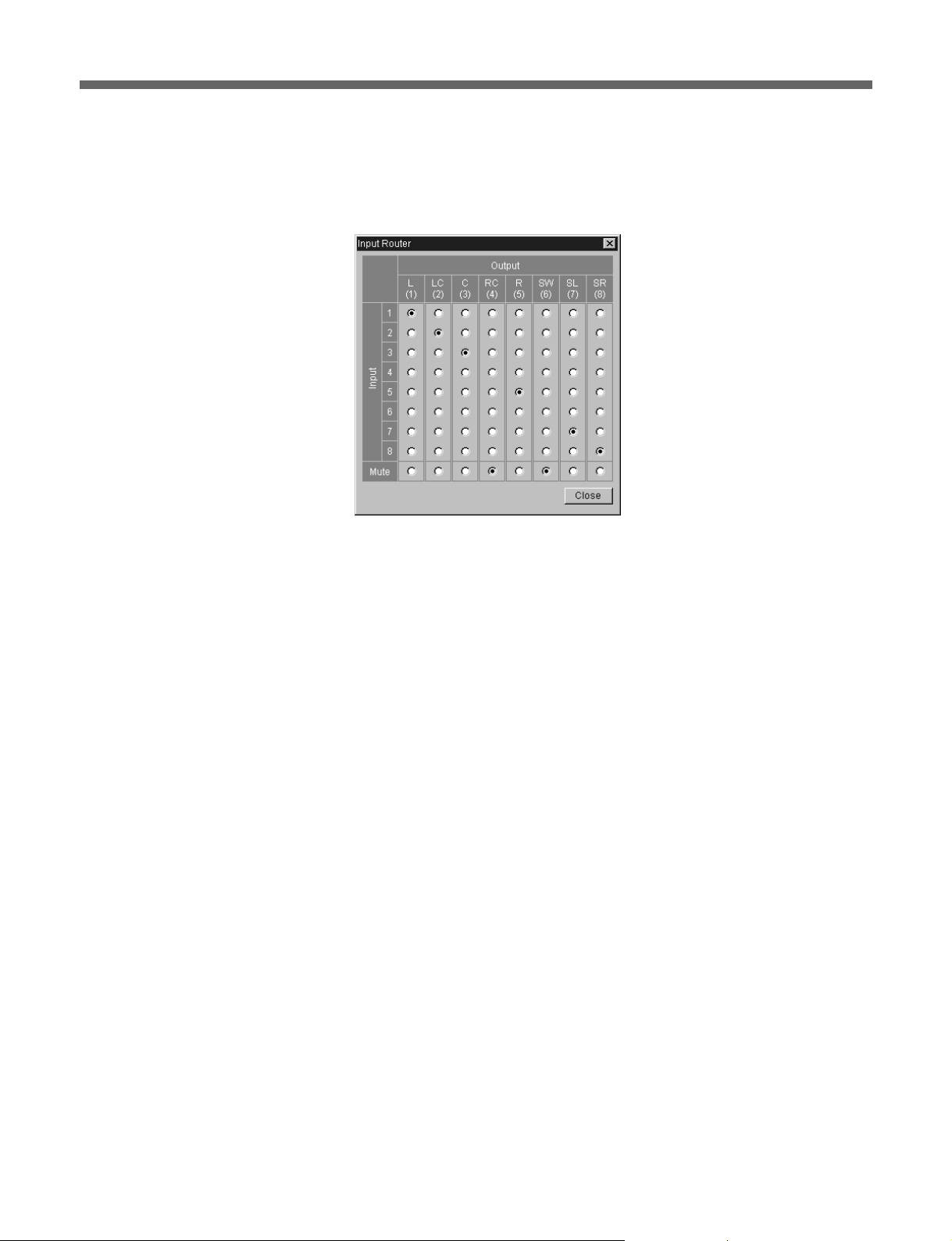
Input Routing box
Changes the channel allocation of the input audio signal. Select Through
for normal use. Select Input Router to display the Input Router window as
follows:
Input Router window
Using this window, change the channel allocation of the input audio signal
and/or mute any channels of audio output signal.
LED Power boxes
Adjusts the LED power of the DFR-C3000. Enter the value according to
the result of density test in the P box and S box.
Film Title box
Type in the title of the film. Up to 64 alphanumeric characters can be
entered.
Roll Number box
Select the roll number of the film from 0 to 31.
Version box
Select the version of the film from 0 to 99.
Comments box
Type in the comments for the film. Up to 14 alphanumeric characters can
be entered.
Density Patch column
Displays the method of detecting the position where the density patch is
recorded and position of the detected density patch. These settings can be
done using the Header/Footer menu. Click bHeader/Footer to jump to the
Header/Footer menu.
19(E)

Software Operation
Audio Monitor Select column
Selects the audio signal output to the ANALOG OUT connector.
•When you click Main, ATRAC-encoded main channel is output.
•When you click DCM, ATRAC-encoded concealment channel is output.
•When you click Input, input audio channel is output as is.
Measurement column
Select the unit for displaying the current position.
Current Position column
Displays the current recording position.
The contents of this column changes only during recording.
The contents of each box change according to the setting of Measurement
column as follows:
Information displayed in the Current Position column
Box title Selection in the
Time Code —
Film Length Feet/Frame The film length from the recording
Time From
Start
Remaining Feet/Frame The remaining film length up to the
Remaining
Time
Measurement column
Time The time that has elapsed since the
Time The remaining time up to the recording
Information
The current time code on the master
tape in hours, minutes, seconds and
frames.
starting point in feet and frames.
start of recording in hours, minutes,
and seconds.
recording stopping point in feet and
frames.
stopping point in hours, minutes and
seconds.
20(E)
Event column
Specify the start and stop position for the automatic recording.
TC Type box
Select Time Code or Feet/Frame for the unit for measuring events.
•When you select Time Code, events are measured in accordance with
input time code.
•When you select Feet/Frame, events are measured in accordance with
total length of transport from the beginning of the film.
Start Time box
Specify the recording start time if Time Code is selected for TC Type box.
Stop Time box
Specify the recording stop time if Time Code is selected for TC Type box.

Duration box
Specify the recording duration regardless of the item selected for TC Type
box.
If Time Code is selected, the value in Duration box is automatically
updated when you change the recording start or stop time. Also, when you
change the value in Duration box, recording stop time indication is
automatically updated.
Record buttons
Auto button
Click to start automatic recording.
When Time Code is selected for TC Type box, recording automatically
starts regardless of the value in Start Time box and automatically stops
according to the value in Stop Time box. When Feet/Frame is selected,
recording starts and continues for the length of the film specified in
Duration box, and automatically stops.
Start Camera button
Click to start recording manually.
Recording continues until you click the Stop Camera button.
Stop Camera button
Click to stop recording.
When you click this button, both automatic recording and manual
recording stop.
During recording, the information in the Current Position column is
updated in real time.
Also, status message appears in Status Line (located at the bottom of the
screen) to show the progress of recording.
Load Pattern button
Click to load the additional pattern from the floppy disc.
Be sure to insert the floppy disc in the drive A.
Recall Parameters button
Click to recall the parameters saved by clicking the Save Parameters
button below.
Save Parameters button
Click to save the recording parameters in the specified file in the hard disc.
All parameters except Footer parameters in Density Patch column are
saved to the hard disc.
Note that the previously saved parameters are overwritten by the new
parameters.
21(E)
Software Operation
Header/Footer Menu
Going to another menu
Click the respective menu button.
If an error occurs in the system
The “OK” indication in the System Condition box in the top-right section
of the screen changes to “NG”. Click the box to obtain help. A window
will appear to explain the cause of the problem.
22(E)
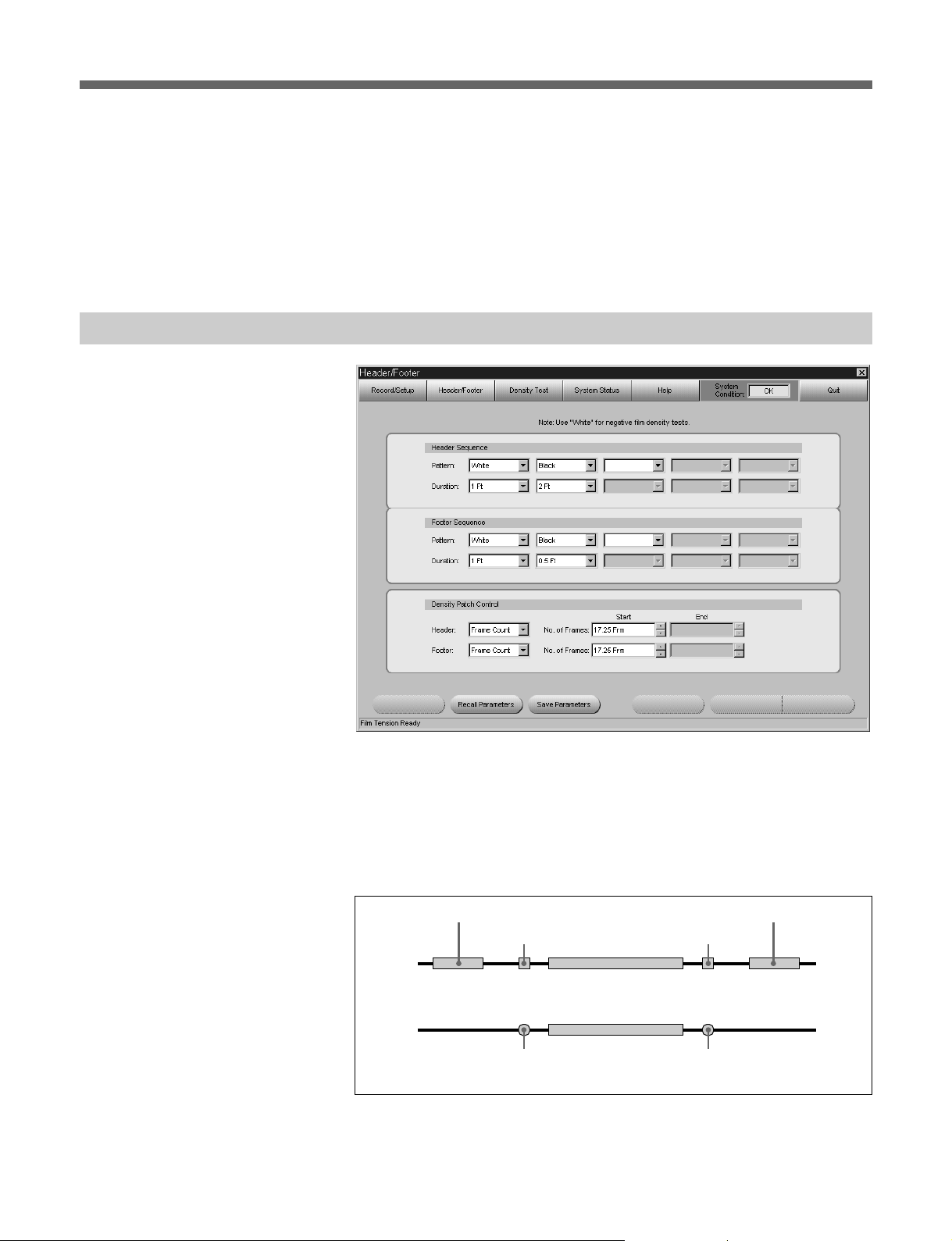
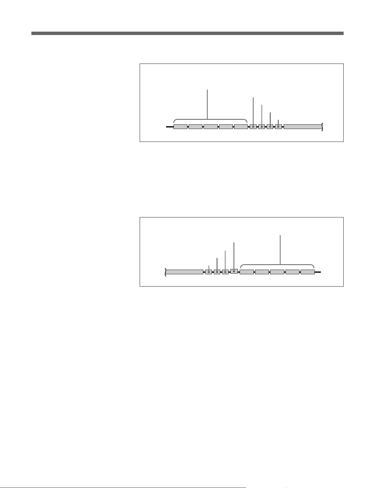
Use this menu to set the film header, footer, and density patch. Prior to
recording, header, footer, and density patch must be defined.
The header, footer, and density patch are used to check the difference
between the black and white levels and to make sure that data can be read
correctly.
The recording position of each item is shown in the figure below:
SDDS
track
Analog
track
Film head
Header
Head density patch
POP signal POP signal
Foot density patch
Audio signals
Footer
Film tail
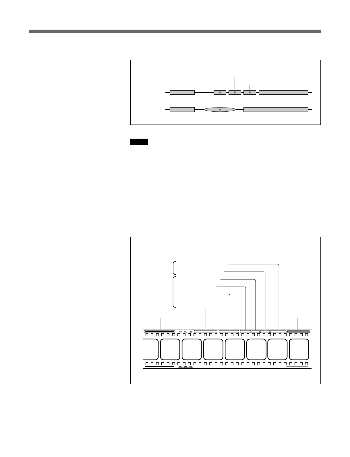
Header sequence
User-defined density measurement patterns
Up to five patterns each of which is 0.5 to 6.0
foot long can be selected
Short density test pattern
SDDS logo
Additional pattern (if specified)
Film head
Visual ID
Audio signal
Film tail
To specify the header sequence, select the pattern from the leftmost Pattern
box. Whilte, Black, or Checker can be selected. Then select the duration
in the leftmost Duration box. Duration can be specified between 0.5 foot
and 6.0 foot, in 0.5 foot units. Repeat this procedure to specify all the
items from left to right.
You can define up to five patterns and duration for each header.
Footer sequence
User-defined density measurement patterns
Up to five patterns each of which is 0.5 to 6.0 foot long can be selected
Visual ID
Additional pattern (if specified)
SDDS logo
Short density test pattern
Film head
Film tail
Audio signal
Use the procedure for defining a header sequence above to define a footer
sequence.
Density Patch Control column
Specifies the method of detecting the positions where the density patches
will be recorded. Set the positions where the POP signal is recorded in
order to record the density patch in the same positions. Time Code, Feet/
Frame, or POP signal can be selected as the method of detecting the
positions where the density patches will be recorded.
•When you select Time Code, type in the time you want the density patch
to be recorded in Start box. The same time unit is used as the time code
input from the TIME CODE connector.
•When you select Feet/Frame, type in the time you want the density patch
to be recorded in Start box. Feet and frame are used for time units.
•When you select POP signal, type in the start point and end point of the
recorded POP signal in Start box and End box, respectively. Feet and
frame are used as units.
If the recording of the footer density patch is unnecessary, select None as
the method of detecting the positions where the footer density patches will
be recorded.
23(E)
Software Operation
LED Power P=15, S=16 " In the Line of Fire
"
Roll No. 03 Ver. 02 s/n10010 R-S/N000000A1
" In the Line of Fire
LED Power P=15, S=16
"
Roll No. 03Ver. 02
s/n10010 R-S/N000000A1
Density patch is recorded as shown in the figure below:
White
Film head
SDDS track
Analog track
Film tail
Audio signal
(one frame each)
Black
Visual ID
Audio signal
Notes
•The number of frames in the time code will differ depending on the type
of the time code. Operation error may occur if the frame which does not
exist in the input time code is specified.
•When POP signal is selected, if signals similar to the POP signal are
detected within the specified duration, density patch is recorded in the
position that the first signal is detected.
About the visual ID
When recording digital audio signals, the system automatically records a
visual ID (as shown below) before and after the digital audio signals (i.e.,
after the header and before the footer).
Parameters set
with the System
Status menu
Parameters set
with the
Record/Setup
menu
Density measurement pattern
(selectable duration)
Recording serial No.
Camera serial No.
Version number
Roll number
Film title
LED power values for
the P side and S side
Visual ID
Encoded digital
audio signals
Recall Parameters button
Click to recall the parameters saved by clicking the Save Parameters
button below.
24(E)
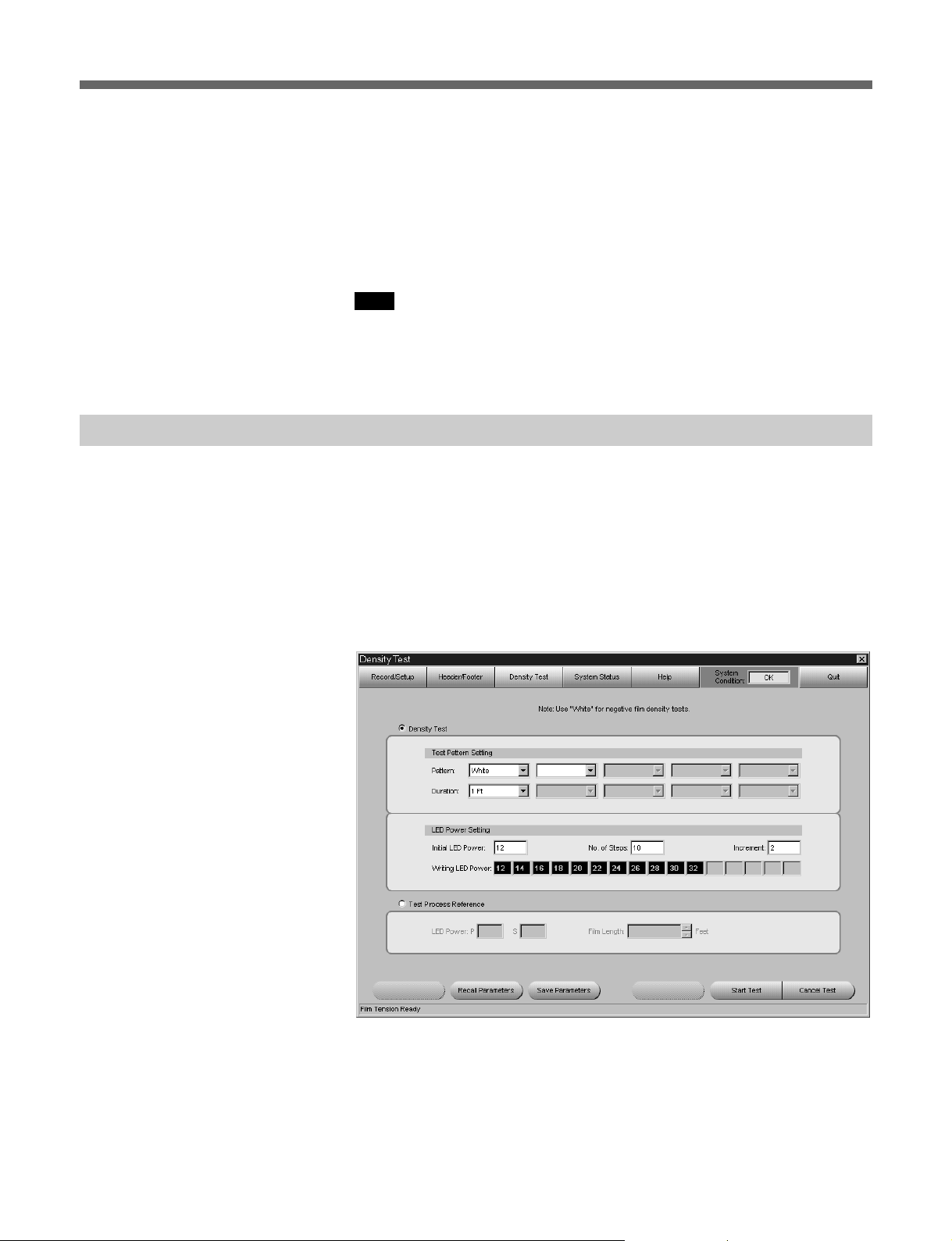
Density T est Menu
Save Parameters button
Click to save the parameters in the specified file in the hard disc.
Parameters save to the hard disc are as follows:
Header and Footer Sequence parameters, Header Start position, and
Header End position in Density Patch Control column.
Note that the previously saved parameters are overwritten by the new
parameters.
Note
The following parameters are not saved to the hard disc:
Footer Start position and Footer End position in Density Patch Control
column.
Prior to recording, you can do a density test in order to set the LED power
to its optimum level. In this test, a user-defined test pattern sequence is
recorded onto the film repeatedly, with an increase in LED power with
each successive image. This test is required only when the current LED
power setting seems to be inappropriate.
Pattern White is a mode used to record on the negative film with a fixed
level of LED power. The film recorded in this mode is used to verify the
development process in film laboratories.
Defining the test pattern sequence
1 Select the pattern from the leftmost Pattern box in the Test Pattern
Setting column.
2 Select the duration from the leftmost Duration box in the Test Pattern
Setting column.
25(E)

Software Operation
3 Repeat steps 1 and 2 to define additional patterns and duration. (You
can define up to five patterns and duration.)
LED Power Setting column
Initial LED Power box
Type in the initial level of the LED power for the test pattern.
No. of Steps box
Type in the number of times for the test patterns to be recorded.
Increment box
Type in the increment of LED power for each test pattern.
Writing LED Power boxes
Sequence of density test pattern is displayed.
Test Process Reference column
LED Power boxes
Type in the level of the LED power for recording.
Film Length box
Type in the film length to be recorded in integral number (1 to 50).
Start Test button
Click to start recording for the density test or white test film.
The test continues for feet specified in Film Length box and stops
automatically.
Cancel Test button
Click to cancel the recording.
Recall Parameters button
Click to recall the parameters saved by clicking the Save Parameters
button below.
Save Parameters button
Click to save the parameters in the specified file in the hard disc.
Parameters save to the hard disc are as follows:
Test Pattern Setting and LED Power Setting in Density Test column, and
Film Length in Test Process Reference column.
Note that the previously saved parameters are overwritten by the new
parameters.
26(E)
Note
LED Power settings in the Test Process Reference column is linked to the
LED Power setting in Record/Setup menu, therefore, this setting is not
saved to the hard disc.
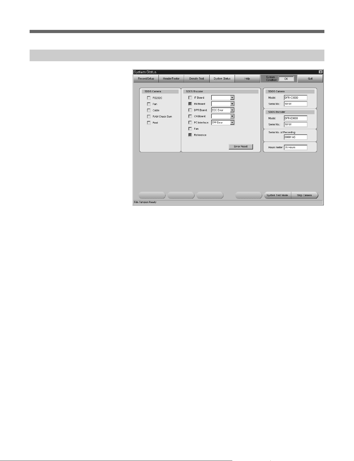
System Status Menu
If an error occurs, the square for the location where the error has been
detected lights up red.
If a warning is issued, the corresponding square lights up yellow.
When an error and warning occurred at the same time, the square lights up
red.
If more than one errors have occurred in one location, a list of errors
appears in the box to the right of the location.
For details, contact your nearest Sony dealer or service personnel.
Error Reset button
Click to reset error and warning indication. If the error or warning consists
when you clicked the button, the same error or warning indication appears
after resetting.
System information area
SDDS Camera Model box
The model name of the camera appears.
SDDS Camera Serial No. box
The serial number of the camera appears.
SDDS Encoder Model box
The model name of the encoder appears.
SDDS Encoder Serial No. box
The serial number of the encoder appears.
Serial No. of Recording box
The serial number of the film recorded using the camera appears.
27(E)

Software Operation
Hours Meter box
The total film running time of your camera in hours.
Stop Camera button
Click to stop recording.
28(E)
Loading...