


DCR-TRV725E
Table of contents
 Loading...
DCR-TRV725E/TRV730E/
SERVICE MANUAL
SERVICE MANUAL
TRV828E/TRV830E
RMT-814
AEP Model
Level 1
Ver 1.0 2001. 03
Video camera
recorder
System
Video recording system
2 rotary heads
Helical scaning system
Audio recording system
Rotary heads, PCM system
Quantization: 12 bits (Fs 32 kHz,
stereo 1, stereo 2), 16 bits
(Fs 48 kHz, stereo)
Video signal
PAL colour, CCIR standards
Recommended cassette
Hi8/Digital8 video cassette
Recording/playback time (using
90 min. Hi8 video cassette)
SP mode: 1 hour
LP mode: 1 hour and 30 minuites
Fastforward/rewind time (using
90 min. Hi8 video cassette)
Approx. 5 min.
Viewfinder
Electric Viewfinder, Monochrome
Image device
4.5 mm (1/4 type CCD)
(Charge Coupled Device)
Approx. 1 070 000 pixels
(Memory mode: 1 000 000 pixels)
(Camera mode: 690 000 pixels)
Lens
Combined power zoom lens
Filter diameter 37 mm (1 1/2 in.)
18× (Optical), 500×
(Digital)
Photo : DCR-TRV730E
RMT-814
SPECIFICATIONS
Focal length
4.1 – 73.8 mm (3/16 – 3 in.)
When converted to a 35 mm still
camera
Camera mode:
47 – 846 mm (1 7/8 – 33 3/8 in.)
Memory mode:
39 - 702 mm (1 9/16 – 27 3/4 in.)
Colour temperature
Auto
Minimum illumination
7 lx (lux) (F 1.8)
0 lx (lux) (in the NightShot mode)*
* Objects unable to be seen due to
the dark can be shot with infrared
lighting.
Input/output
connectors
S video input/output
4-pin mini DIN
Luminance signal: 1 Vp-p,
75 Ω (ohms), unbalanced
Chrominance signal: 0.3 Vp-p, 75 Ω
(ohms), unbalanced
Audio/Video input/output
AV MINIJACK, 1 Vp-p, 75 Ω
(ohms), unbalanced, sync negative
327 mV, (at output impedance more
than 47 kΩ (kilohms))
Output impedance with less than
2.2 kΩ (kilohms)/Stereo minijack
(ø 3.5 mm)
Input impedance more than 47 kΩ
(kilohms)
Headphone jack
Stereo minijack (ø 3.5 mm)
USB jack
mini-B
LANC
jack
Stereo mini-minijack (ø 2.5 mm)
MIC jack
Stereo minijack (ø 3.5 mm)
DV input/output
4-pin connector
LCD screen
Picture
DCR-TRV725E/TRV730E:
6.2 cm (2.5 type)
50.3 × 37.4 mm (2 × 1 1/2 in.)
DCR-TRV828E/TRV830E:
8.8 cm (3.5 type)
72.2 × 50.4 mm (2 7/8 × 2 in.)
Total dot number
123 200 (560 × 220)
General
Power requirements
7.2 V (battery pack)
8.4 V (AC power adaptor)
Average power consumption
(when using the battery pack)
During camera recording using
LCD
DCR-TRV725E/TRV730E:
4.7 W
DCR-TRV828E/TRV830E:
5.0 W
Viewfinder
3.8 W
UK Model
M2000 MECHANISM
Operating temperature
0 °C to 40 °C (32 °F to 104 °F)
Storage temperature
–20 °C to +60 °C (–4 °F to +140 °F)
Dimensions (Approx.)
89 × 102 × 227 mm
(3 5/8 × 4 1/8 × 9 in.) (w/h/d)
Mass (approx.)
DCR-TRV725E/TRV730E:
970 g (2 lb 2 oz)
DCR-TRV828E/TRV830E:
980 g (2 lb 2 oz)
excluding the battery pack, cassette
and shoulder strap
DCR-TRV725E/TRV730E:
1 120 g (2 lb 7 oz)
DCR-TRV828E/TRV830E:
1 130 g (2 lb 7 oz)
including the battery pack
NP-FM50, 90min. Hi8 cassette, and
shoulder strap
Supplied accessories
See page 3.
DIGITAL VIDEO CAMERA RECORDER

Table for difference of function
DCRLCD Size
VTR Rec mode
Printer
TRV725E
✕
TRV730E
2.5 inch
TRV828E
a
✕
TRV830E
3.5 inch
Remark
a: with REC button
a
a: with printer
SAFETY-RELATED COMPONENT WARNING!!
COMPONENTS IDENTIFIED BY MARK 0 OR DOTTED LINE WITH
MARK 0 ON THE SCHEMATIC DIAGRAMS AND IN THE PARTS
LIST ARE CRITICAL TO SAFE OPERATION. REPLACE THESE
COMPONENTS WITH SONY PARTS WHOSE PART NUMBERS
APPEAR AS SHOWN IN THIS MANUAL OR IN SUPPLEMENTS
PUBLISHED BY SONY.
SAFETY CHECK-OUT
After correcting the original service problem, perform the following
safety checks before releasing the set to the customer.
1. Check the area of your repair for unsoldered or poorly-soldered
connections. Check the entire board surface for solder splashes
and bridges.
2. Check the interboard wiring to ensure that no wires are
"pinched" or contact high-wattage resistors.
3. Look for unauthorized replacement parts, particularly
transistors, that were installed during a previous repair . Point
them out to the customer and recommend their replacement.
4. Look for parts which, through functioning, show obvious signs
of deterioration. Point them out to the customer and
recommend their replacement.
5. Check the B+ voltage to see it is at the values specified.
6. Flexible Circuit Board Repairing
• Keep the temperature of the soldering iron around 270˚C
during repairing.
• Do not touch the soldering iron on the same conductor of the
circuit board (within 3 times).
• Be careful not to apply force on the conductor when soldering
or unsoldering.
— 2 —

Checking supplied accessories.
Make sure that the following accessories are supplied with your camcorder.
Wireless Remote Commander (1)
RMT-814
1-475-141-61
Size AA (R6) battery for
Remote Commander (2)
(not supplied)
Memory Stick (1)
A-7033-740-A
CD-ROM
(SPVD-004 USB Driver)(1)
3-066-676-01
AC-L10A
AC power adaptor (1)
0
1-475-599-11
A/V connecting cable (1.5m) (1)
1-765-080-11
21-pin adaptor (1)
1-573-291-11
Power cord (Mains lead)(1) (AEP model)
0
1-769-608-11
Power cord (Mains lead)(1) (UK model)
0
1-783-374-11
Shoulder strap (1)
3-987-015-01
Printer (PVP-MSH) (1)
(not supplied)
(DCR-TRV830E only)
Lens cap (1)
X-3949-376-1
NP-FM50 battery pack (1)
(not supplied)
USB cable (1)
1-757-293-11
Print paper (1)
Standard type
(10 sheets × 1)
Stickey type/Standard size
(5 sheets × 1)
Stickey type/9 sprits size
(5 sheets × 1)
(not supplied)
Print cartridge (1)
(not supplied)
Head cleaner (1)
(not supplied)
Plate roller cleaner (1)
(not supplied)
Other accessories
3-066-295-11 MANUAL, INSTRUCTION (PVP-MSH)
3-066-295-21 MANUAL, INSTRUCTION (PVP-MSH)(GERMAN/DUTCH)
3-066-295-31 MANUAL, INSTRUCTION (PVP-MSH)(ITALIAN/SWEDISH)
3-066-295-41 MANUAL, INSTRUCTION (PVP-MSH)
3-066-295-51 MANUAL, INSTRUCTION (PVP-MSH)
3-066-295-71 MANUAL, INSTRUCTION (PVP-MSH)
(SIMPLIFIED CHINESE/GREEK/PERSIAN)(TRV830E:AEP)
(ENGLISH/FRENCH/SPANISH)(TRV830E)
(TRV830E:AEP)
(TRV830E:AEP)
(PORTUGUESE/POLISH)(TRV830E:AEP)
(RUSSIAN/TRADITIONAL CHINESE)(TRV830E)
3-066-522-11 MANUAL, INSTRUCTION (ENGLISH/RUSSIAN)
3-066-522-21 MANUAL, INSTRUCTION (FRENCH/GERMAN)(AEP)
3-066-522-31 MANUAL, INSTRUCTION (ENGLISH/DUTCH)(AEP)
3-066-522-41 MANUAL, INSTRUCTION (SPANISH/PORTUGUESE)(AEP)
3-066-522-51 MANUAL, INSTRUCTION (ITALIAN/GREEK)(AEP)
Note : The components identified by mark 0 or dotted
line with mark 0 are critical for safety.
Replace only with part number specified.
— 3 —

TABLE OF CONTENTS
SERVICE NOTE
1. POWER SUPPLY DURING REPAIRS ····························· 5
2. TO TAKE OUT A CASSETTE WHEN NOT EJECT
(FORCE EJECT) ································································ 5
SELF-DIAGNOSIS FUNCTION
1. Self-diagnosis Function ······················································ 6
3. Service Mode Display ························································ 6
3-1. Display Method ·································································· 6
3-2. Switching of Backup No. ··················································· 6
3-3. End of Display····································································6
2. Self-diagnosis Display························································ 6
4. Self-diagnosis Code Table ·················································· 7
1. MAIN PARTS
1. ORNAMENTAL PARTS···················································· 9
2. DISASSEMBLY······························································· 10
2-1. LCD UNIT, PD-139 BOARD
(2.5 INCH LCD MODEL)(TRV725E/TRV730E) ··········· 11
2-2. LCD UNIT, PD-139 BOARD
(3.5 INCH LCD MODEL)(TRV828E/TRV830E) ··········· 12
2-3. FRONT PANEL SECTION, SI-030 BOARD ·················· 13
2-4. CABINET (R) SECTION ················································ 14
2-5. CONTROL SWITCH BLOCK (SE-1380),
FP-315 BOARD ······························································· 14
2-6. CF-084 BOARD······························································· 15
2-7. EVF SECTION, LB-071 BOARD ··································· 15
2-8. LENS SECTION, CD-329 BOARD ································ 16
2-9. MM-043 BOARD····························································· 16
2-10. BATTERY PANEL SECTION,
BATTERY TERMINAL BOARD ···································· 16
2-11. CONTROL SWITCH BLOCK (SS-1380),
FU-155 BOARD······························································· 17
2-12. CABINET (L) SECTION, MECHANISM DECK-1 ······· 17
2-13. VC-262 BOARD ······························································ 18
2-14. MECHANISM DECK-2, MD FRAME (M) ···················· 18
2-15. HINGE SECTION···························································· 19
3. REPAIR PARTS LIST······················································ 20
3-1. EXPLODED VIEWS ······················································· 20
3-1-1.OVERALL SECTION······················································ 20
3-1-2.CABINET (L) SECTION-1 ············································· 21
3-1-3.CABINET (L) SECTION-2 ············································· 22
3-1-4.CABINET (R) SECTION ················································ 23
3-1-5.LCD SECTION ································································ 24
3-1-6.LENS, EVF SECTION····················································· 25
2. GENERAL
Checking supplied accessories ··················································· 26
Main Features ············································································ 26
Quick Start Guide ······································································· 26
Getting started
Using this manual ·································································· 27
Step 1 Preparing the power supply ········································· 27
Installing the battery pack···················································· 27
Charging the battery pack ··················································· 28
Connecting to a wall socket ················································· 29
Step 2 Setting the date and time ············································· 29
Step 3 Inserting a cassette······················································ 30
Recording – Basics
Recording a picture································································ 30
Shooting backlit subjects – BACK LIGHT ························ 32
Shooting in the dark – NightShot/Super NightShot ············ 32
Self-timer recording····························································· 32
Checking the recording – END SEARCH/EDITSEARCH/
Rec Review ········································································· 33
Playback – Basics
Playing back a tape ································································· 33
Viewing the recording on TV ················································· 35
Advanced Recording Operations
Recording a still image on a tape – Tape Photo recording ····· 36
Using the wide mode ····························································· 37
Using the fader function ························································· 37
Using special effects – Picture effect····································· 38
Using special effects – Digital effect······································ 38
Using the PROGRAM AE function ········································ 39
Adjusting the exposure manually ··········································· 40
Focusing manually·································································· 40
Superimposing a title ······························································ 40
Making your own titles ·························································· 41
Inserting a scene ····································································· 41
Advanced Playback Operations
Playing back a tape with picture effects ································· 42
Playing back a tape with digital effects ·································· 42
Enlarging recorded images – Tape PB ZOOM ······················· 42
Quickly locating a scene using the zero set memory function ·
Searching a recording by date – Date search·························· 43
Searching for a photo – Photo search/Photo scan··················· 44
Editing
Dubbing a tape ······································································· 44
Dubbing only desired scenes – Digital program editing ········ 45
Using with analog video unit and your computer
– Signal convert function
(DCR-TRV730E/TRV828E/TRV830E only) ····················· 48
Recording video or TV programmes
(DCR-TRV730E/TRV828E/TRV830E only) ····················· 49
Inserting a scene from a VCR – Insert Editing
(DCR-TRV730E/TRV828E/TRV830E only) ······················ 50
Customizing Y our Camcorder
Changing the menu settings···················································· 50
“Memory Stick” operations
Using “Memory Stick”–introduction······································ 53
Recording still images on “Memory Stick”
– Memory Photo recording ················································· 55
Recording an image from a tape as a still image ···················· 57
Recording moving pictures on “Memory Stick”s
– MPEG movie recording ···················································· 58
Recording moving pictures from a tape·································· 58
Superimposing a still image in the “Memory Stick” on
an image – MEMORY MIX ················································ 59
Copying still images from a tape – Photo save······················· 61
Viewing a still image – Memory Photo playback··················· 61
Viewing a moving picture – MPEG movie playback ············ 62
Viewing images using your computer ··································· 63
Copying the image recorded on “Memory Stick” to tapes
(DCR-TRV730E/TRV828E/TRV830E only) ····················· 64
Enlarging still images recorded on “Memory Stick”s
– Memory PB ZOOM ·························································· 65
Playing back images in a continuous loop – SLIDE SHOW· 65
Preventing accidental erasure – Image protection ·················· 66
Deleting images ····································································· 66
Writing a print mark – PRINT MARK·································· 67
Using the external printer ······················································ 67
Troubleshooting
Types of trouble and their solutions········································ 68
Self-diagnosis display ····························································· 69
Warning indicators and messages ··········································· 69
Additional Information
Digital8
About the “InfoLITHIUM” battery pack······························· 70
About i.LINK·········································································· 71
Using your camcorder abroad················································· 71
Maintenance information and precautions······························ 72
Quick Reference
Identifying the parts and controls ··········································· 73
system, recording and playback··························· 70
43
— 4 —
SERVICE NOTE
1. POWER SUPPLY DURING REPAIRS
In this unit, about 10 seconds after power is supplied (8.4V) to the battery terminal using the service power code (J-6082-223-A), the po wer
is shut off so that the unit cannot operate.
These following two methods are available to prevent this. Take note of which to use during repairs.
Method 1.
Use the DC IN terminal. (Use the AC power adaptor.)
Method 2.
Connect the adjustment remote commander RM-95 (J-6082-053-B) to the LANC jack, and set the HOLD switch to the “ADJ” side.
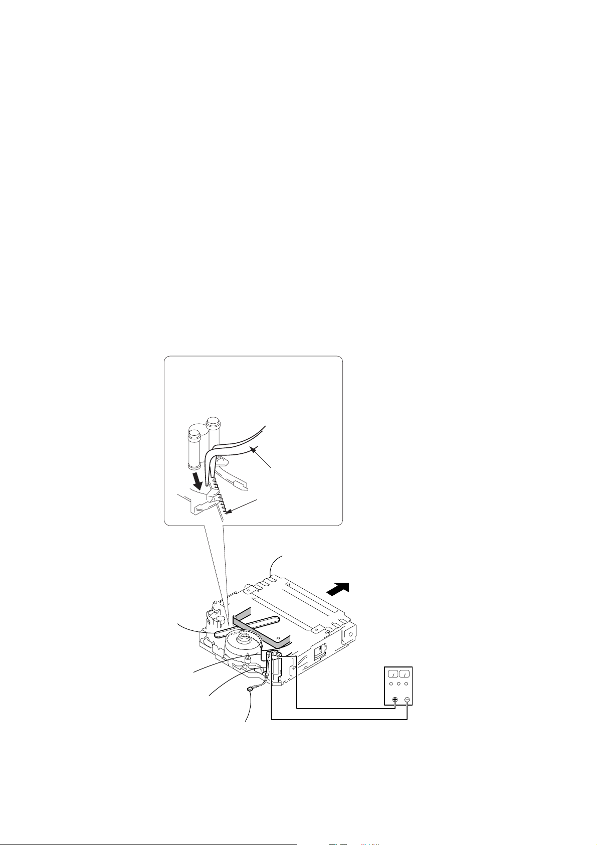
2. TO TAKE OUT A CASSETTE WHEN NOT EJECT (FORCE EJECT)
1 Refer to 2-3. to remove the front panel section.
2 Refer to 2-4. to remove the cabinet (Upper) assembly.
3 Refer to 2-4. to remove the cabinet (R) assembly.
4 Refer to 2-9. to remove the memory stick connector assembly.
5 Refer to 2-10. to remove the battery panel section.
6 Refer to 2-11. and 2-12. to remove the cabinet (L) section. (Include the CS frame assembly and control switch block (SS-1380).)
7 Disconnect CN4401 (2P) of VC-262 board.
8 Add +5V from the DC POWER SUPPLY and unload with a pressing the cassette compertment.
9
Pull the timing belt in the direction of
arrow
the cassette compartment (take care
not to damage) to adjust the bending
of a tape.
A
Timing belt
Adjust the bending
of a tape
Loading
motor
A
with a pincette while pressing
Pincette
Timing belt
Press the cassette compartment not
to rise the cassette compartment
0
Let your hold the cassette
compartment and rise the cassette
compartment to take out a cassette.
DC power supply
(+5V)
Disconnect CN4401 of
VC-262 board
— 5 —
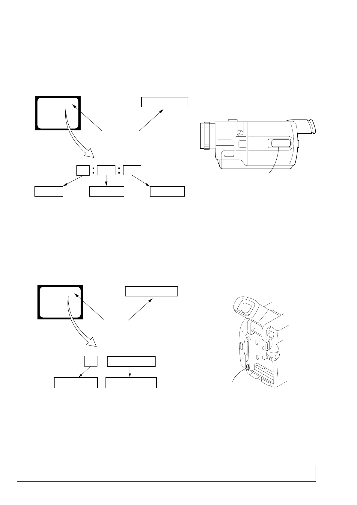
SELF-DIAGNOSIS FUNCTION
Control dial
1. Self-diagnosis Function
When problems occur while the unit is operating, the self-diagnosis
function starts working, and displays on the viewfinder or Display
window what to do. This function consists of two display; selfdiagnosis display and service mode display .
Details of the self-diagnosis functions are provided in the Instruction
manual.
Viewfinder Display window
C : 3 1 : 1 1
Repaired by:
C : Corrected by customer
H : Corrected by dealer
E : Corrected by service
engineer
Blinks at 3.2Hz
C
Indicates the appropriate
step to be taken.
E.g.
31 ....Reload the tape.
32 ....Tu r n o n power again.
3 1
Block
1 1
C : 3 1 : 11
Detailed Code
Refer to page 7 and 8.
Self-diagnosis Code Table.
2. Self-diagnosis Display
When problems occur while the unit is operating, the counter of the
viewfinder or Display window shows a 4-digit display consisting
of an alphabet and numbers, which blinks at 3.2 Hz. This 5-character
display indicates the “repaired by:”, “block” in which the problem
occurred, and “detailed code” of the problem.
Display window
3. Service Mode Display
The service mode display shows up to six self-diagnosis codes shown in the past.
3-1. Display Method
While pressing the “STOP” key, set the switch from OFF to “VTR or PLAYER”, and continue pressing the “STOP” key for 5 seconds
continuously. The service mode will be displayed, and the counter will show the backup No. and the 5-character self-diagnosis codes.
Viewfinder
[3] C : 3 1 : 1 1
Lights up
[3]
Backup No.
Order of previous errors
C : 3 1 : 1 1
Self-diagnosis Codes
3-2. Switching of Backup No.
By rotating the control dial, past self-diagnosis codes will be shown in order. The backup No. in the [] indicates the order in which the
problem occurred. (If the number of problems which occurred is less than 6, only the number of problems which occurred will be shown.)
[1] : Occurred first time [4] : Occurred fourth time
[2] : Occurred second time [5] : Occurred fifth time
[3] : Occurred third time [6] : Occurred the last time
Display window
3 C : 3 1 : 11
3-3. End of Display
Turning OFF the power supply will end the service mode display.
Note: The “self-diagnosis display” data will be backed up by the coin-type lithium battery (CF-084 board BT101). When the
CF-084 board is disconnected, the “self-diagnosis display” data will be lost by initialization.
— 6 —

4. Self-diagnosis Code Table
Self-diagnosis Code
Function
Repaired by:
C
C
C
C
C
C
C
C
C
C
C
C
C
C
C
C
C
C
C
C
C
C
C
C
C
C
C
C
C
Block
04
21
22
31
31
31
31
31
31
31
31
31
31
31
31
31
32
32
32
32
32
32
32
32
32
32
32
32
32
Detailed
Code
00
00
00
10
11
20
21
22
23
30
31
40
41
42
43
44
10
11
20
21
22
23
30
31
40
41
42
43
44
Symptom/State
Non-standard battery is used.
Condensation.
Video head is dirty.
LOAD direction. Loading does not
complete within specified time
UNLOAD direction. Loading does not
complete within specified time
T reel side tape slacking when unloading
S reel
side tape slacking when unloading
T reel fault.
S reel fault.
FG fault when starting capstan.
FG fault during normal capstan operations.
FG fault when starting drum.
PG fault when starting drum.
FG fault during normal drum operations.
PG fault during normal drum operations.
Phase fault during normal drum operations.
LOAD direction loading motor time-
out.
UNLOAD direction loading motor
time-out.
T reel side tape slacking when
unloading.
S reel side tape slacking when
unloading.
T reel fault.
S reel fault.
FG fault when starting capstan.
FG fault during normal capstan
operations.
FG fault when starting drum.
PG fault when starting drum.
FG fault during normal drum
operations.
PG fault during normal drum
operations.
Phase fault during normal drum
operations.
Correction
Use the InfoLITHIUM battery.
Remove the cassette, and insert it again after one hour.
Clean with the optional cleaning cassette.
Load the tape again, and perform operations from the beginning.
Load the tape again, and perform operations from the beginning.
.
Load the tape again, and perform operations from the beginning.
.
Load the tape again, and perform operations from the beginning.
Load the tape again, and perform operations from the beginning.
Load the tape again, and perform operations from the beginning.
Load the tape again, and perform operations from the beginning.
Load the tape again, and perform operations from the beginning.
Load the tape again, and perform operations from the beginning.
Load the tape again, and perform operations from the beginning.
Load the tape again, and perform operations from the beginning.
Load the tape again, and perform operations from the beginning.
Load the tape again, and perform operations from the beginning.
Remove the battery or power cable, connect, and perform
operations from the beginning.
Remove the battery or power cable, connect, and perform
operations from the beginning.
Remove the battery or power cable, connect, and perform
operations from the beginning.
Remove the battery or power cable, connect, and perform
operations from the beginning.
Remove the battery or power cable, connect, and perform
operations from the beginning.
Remove the battery or power cable, connect, and perform
operations from the beginning.
Remove the battery or power cable, connect, and perform
operations from the beginning.
Remove the battery or power cable, connect, and perform
operations from the beginning.
Remove the battery or power cable, connect, and perform
operations from the beginning.
Remove the battery or power cable, connect, and perform
operations from the beginning.
Remove the battery or power cable, connect, and perform
operations from the beginning.
Remove the battery or power cable, connect, and perform
operations from the beginning.
Remove the battery or power cable, connect, and perform
operations from the beginning.
— 7 —

Self-diagnosis Code
Function
Repaired by:
E
E
E
E
Block
61
61
62
62
Detailed
Code
00
10
00
01
Symptom/State
Difficult to adjust focus
(Cannot initialize focus.)
Zoom operations fault
(Cannot initialize zoom lens.)
Handshake correction function does not
work well. (With pitch angular velocity
sensor output stopped.)
Handshake correction function does not
work well. (With yaw angular velocity
sensor output stopped.)
Correction
Inspect the lens block focus reset sensor (Pin ql of CN1121 of
VC-262 board) when focusing is performed when the control dial
is rotated in the focus manual mode and the focus motor drive circuit
(IC1554 of VC-262 board) when the focusing is not performed.
Inspect the lens block zoom reset sensor (Pin wa of CN1121 of
VC-262 board) when zooming is performed when the zoom lens is
operated and the zoom motor drive circuit (IC1554 of VC-262
board) when zooming is not performed.
Inspect pitch angular velocity sensor (SE301 of SE-030 board)
peripheral circuits.
Inspect yaw angular velocity sensor (SE302 of SE-030 board)
peripheral circuits.
— 8 —
1. MAIN PARTS
)
Note:
• Follow the disassembly procedure in the numerical order given.
• Items marked “*” are not stocked since they are seldom required for routine service.
Some delay should be anticipated when ordering these items.
• The parts numbers of such as a cabinet are also appeared in this section.
Refer to the parts number mentioned below the name of parts to order.
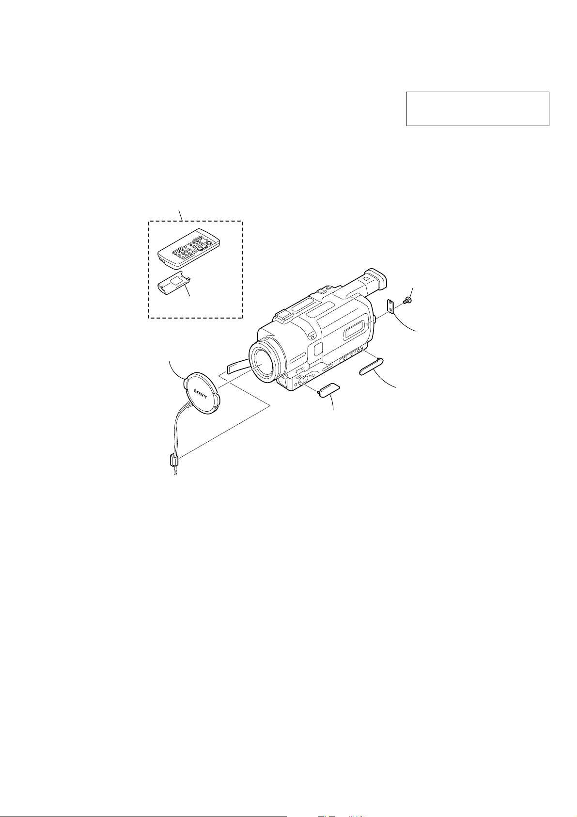
1. ORNAMENTAL PARTS
Remote commander (RMT-814)
1-475-141-61
Battery case lid
3-742-854-01
DCR-TRV725E/TRV730E/
TRV828E/TRV830E
The components identified by mark 0 or
dotted line with mark 0 are critical for safety.
Replace only with part number specified.
×
MI screw (M2
3-067-347-01
4) (H
Lens cap (N) assembly
X-3949-376-1
Jack cover (F)
3-065-352-01
CPC lid (BT)
3-065-325-01
Jack cover (B)
3-065-353-01
— 9 —
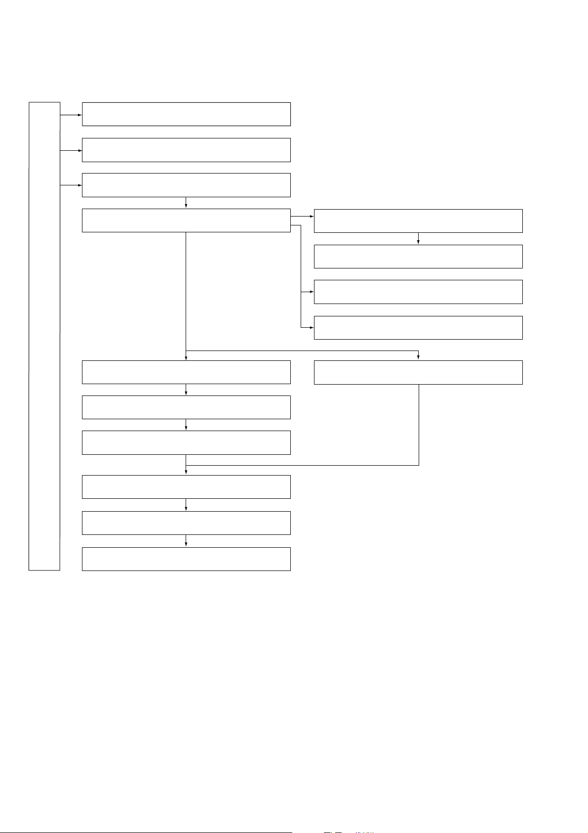
2. DISASSEMBLY
The following flow chart shows the disassembly procedure.
2-1. LCD unit, PD-139 board (2.5 inch LCD model)
2-2. LCD unit, PD-139 board (3.5 inch LCD model)
2-3. Front panel section, SI-030 board
2-4. Cabinet (R) section
2-9. MM-043 board
2-10. Battery panel section, Battery terminal board
DCR-TRV725E/TRV730E/TRV828E/TRV830E
2-11. Control switch block (SS-1380), FU-155 board
2-12. Cabinet (L) section, Mechanism deck-1
2-5. Control switch block (SE-1380), FP-315 board
2-6. CF-084 board
2-7. EVF section, LB-071 board
2-15. Hinge section
2-8. Lens section, CD-329 board
2-13. VC-262 board
2-14. Mechanism deck-2, MD frame (M)
2.5 inch LCD model : DCR-TRV725E/TRV730E
3.5 inch LCD model : DCR-TRV828E/TRV830E
— 10 —
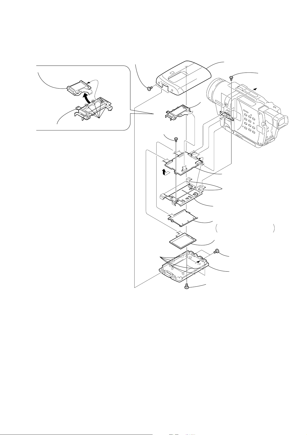
NOTE: F ollo w the disassembly procedure in the numerical order given.
2-1. LCD UNIT, PD-139 BOARD (2.5 INCH LCD MODEL)(TRV725E/TRV730E)
1
REMOVING THE BACK LIGHT
2
Remove the indication LCD (M) block assembly,
back light in the direction of the arrow
C
.
Two MI screws
(M2
×
4) (H)
4
P cabinet C (M) assembly
6
Two screws
(M1.7
A
×
2.5), p
3
LCD holder (M)
C
1
Five claws
9
Screw
(M1.7
B
×
2.5), p
PD-139
Board
5
qz
Remove the PD-139 board
in the direction of the arrow
0
Two claws
qs
P frame (M2),
PD electrostatic sheet (M)
qf
Back light
Cold cathode fluorescent tube,
BL shield sheet (N)
qd
Liquid crystal
indicator module
B
.
3
Four claws
A
7
Two MI screws
(M2
8
P cabinet M (M) assembly
2
Two tapping screws
(M1.7
×
5)
×
4) (H)
— 11 —

2-2. LCD UNIT, PD-139 BOARD (3.5 INCH LCD MODEL)(TRV828E/TRV830E)
REMOVING THE BACK LIGHT
2
Remove the indication LCD (M) block assembly,
back light in the direction of the arrow
C
3
LCD holder (M)
Five claws
1
C
.
1
Two MI screws
×
(M2
4) (H)
9
Screw
(M1.7
B
×
2.5), p
PD-139
Board
5
4
P cabinet C (M) assembly
6
Two screws
(M1.7
A
qa
Remove the PD-139 board in the
direction of the arrow
Two claws
0
qs
P frame (M3),
PD electrostatic sheet (M)
B
.
×
2.5), p
3
Four claws
A
qf
Back light
Cold cathode fluorescent tube,
BL shield sheet (N)
qd
Liquid crystal
indicator module
7
Two MI screws
(M2
8
P cabinet M (M3) assembly
2
Two tapping screws
(M1.7
×
5)
×
4) (H)
— 12 —
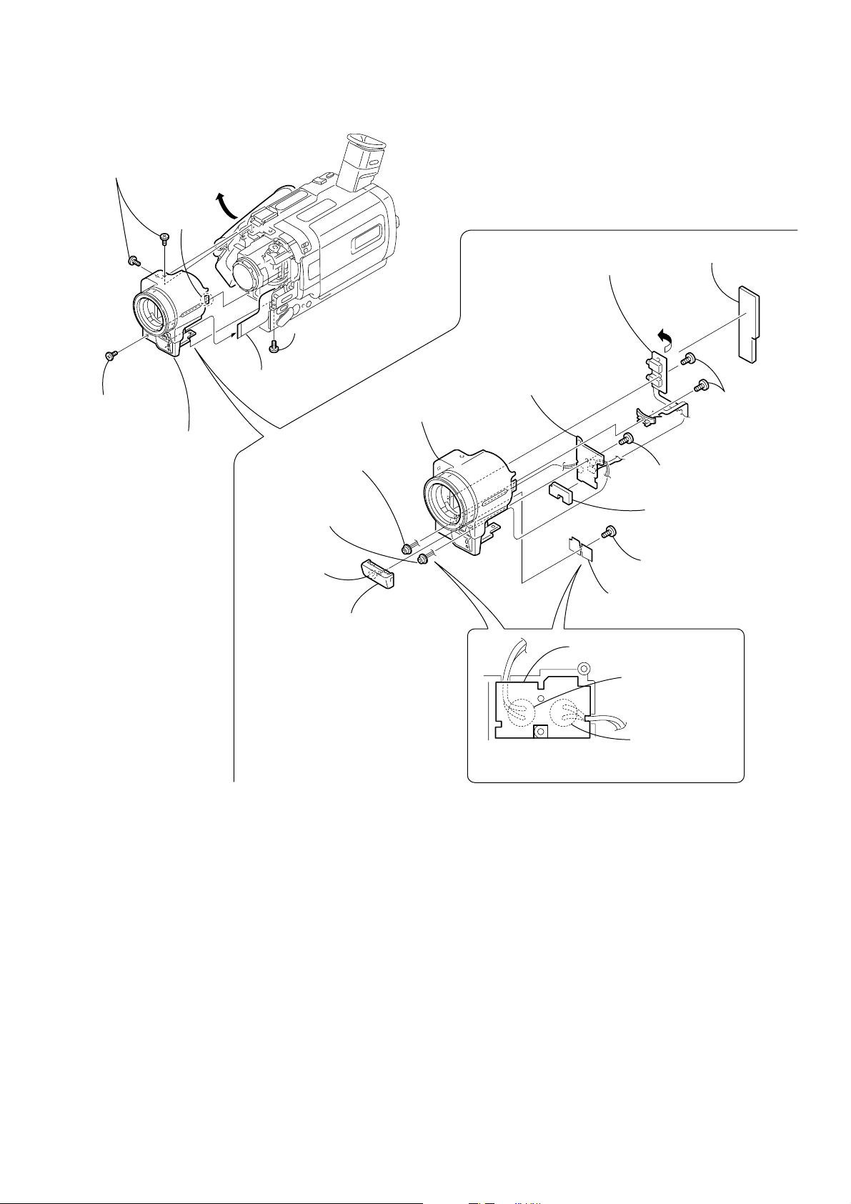
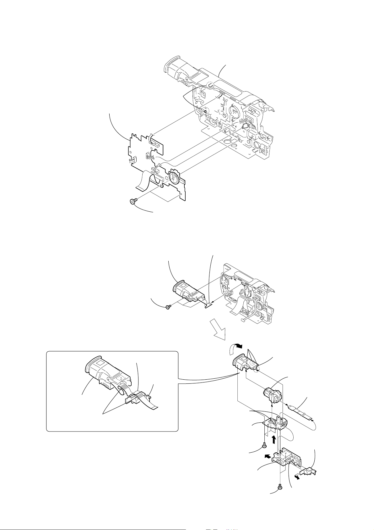
2-3. FRONT PANEL SECTION, SI-030 BOARD
1
4
Two MI screws
×
(M2
4) (H)
Open the cassette
lid.
2
MI screw
(M2
×
4) (H)
7
Front panel section
5
Claw
ita
ig
D
REMOVING THE SI-030 BOARD
3
Remove the FP-273 board in the
B
direction of the arrow
l 8
3
MI screw
(M2
×
4) (H)
6
FP-316 flexible
board (26P)
qd
Front panel
5
SI-030 board
.
B
assembly (M)
qa
Microphone
(Rch)
qs
Microphone
(Lch)
8
Claw
9
Microphone
Digital 8
q;
4
(B2
6
Cushion
(MI)
7
Tapping screw
(B2
Microphone retainer
grille assembly
Microphone retainer (rear view)
1
Cushion (SI)
2
Two tapping
screws
(B2
Tapping screw
×
5)
×
5)
×
5)
Microphone (Lch)
Microphone (Rch)
When removing it, be careful not to damage
the harnesses, etc.
— 13 —
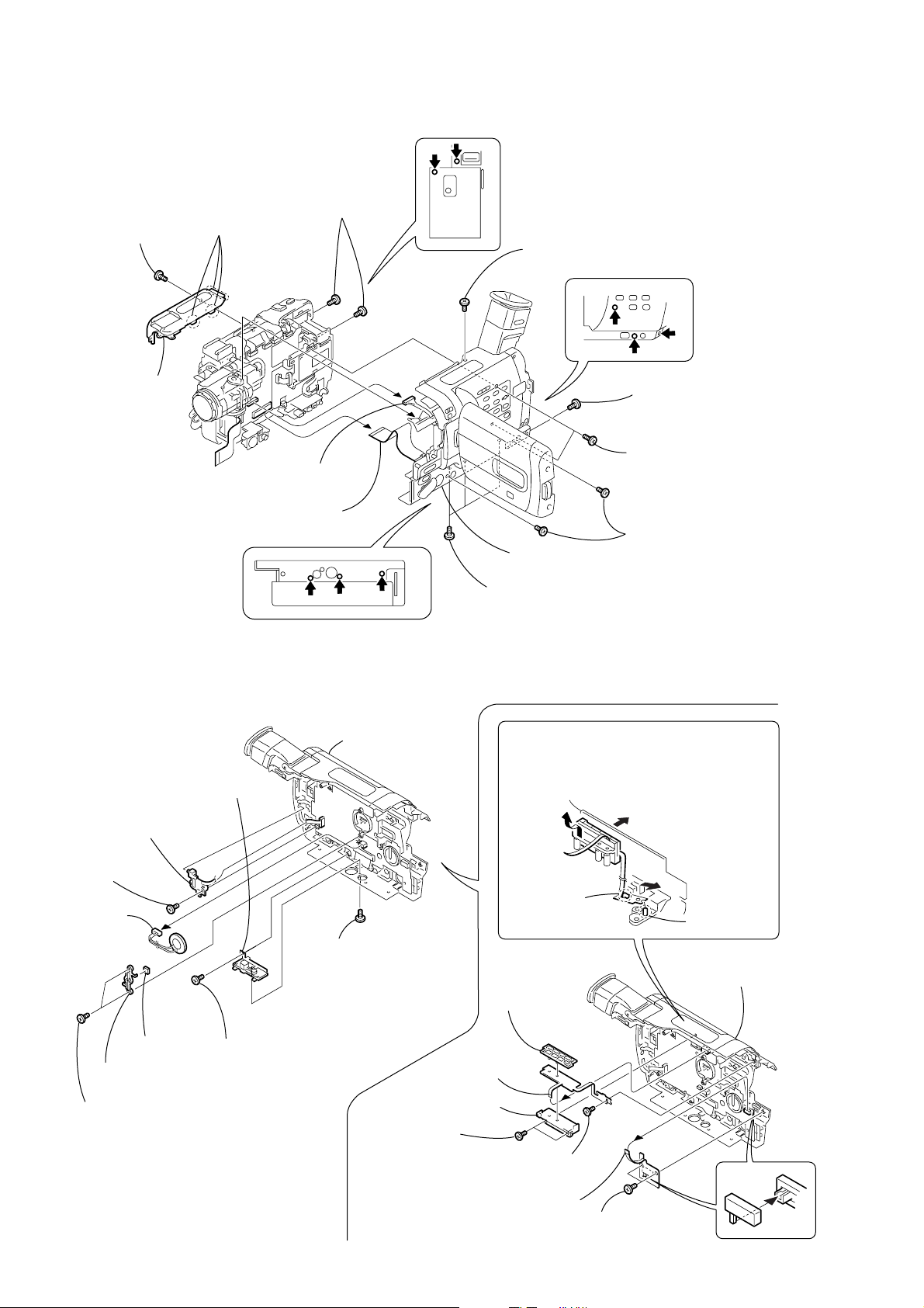
2-4. CABINET (R) SECTION
1
MI screw
(M2 × 4) (H)
3
Cabinet
(upper)
2
Three claws
5
Two MI screws
(M2 × 4) (H)
4
MI screw
(M2 × 4) (H)
6
MI screw
(M2 × 4) (H)
Harness
(VP-076) (20P)
Flexible flat cable
(FFC-001) (45P)
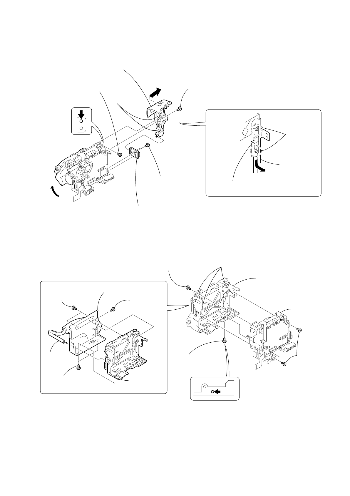
2-5. CONTROL SWITCH BLOCK (SE-1380), FP-315 BOARD
0
Cabinet (R) block
assembly
3
Tripod retainer (M),
Tripod screw
9
Control switch block (SE-1380),
Culupon spacer
8
Tapping screw
(B2 × 5)
5
Speaker
(2.0CM)
6
Speaker
spacer
7
Speaker
retainer
4
Two tapping
screws (B2 × 5)
2
Tapping screw
(B2 × 5)
CF-084
Board
1
MI screw
(M2 × 4) (H)
2
screws (B2 × 5)
1
(8P)
7
VTR holder (M)
Two tapping
FP-315 board
SONY
7
Two tapping screws
(M1.7 × 5)
8
Two MI screws
0
Cabinet (R) block
(M2 × 4) (H)
assembly
9
Three MI screws
(M2 × 4) (H)
REMOVING THE FP-315 BOARD
4
Remove the FP-315 board from the dowel in
the direction A.
5
While pushing the ornamental cabinet (R)
outside in B, remove the VTR button (M)
in the direction C.
B
C
A
Dowel
0
Cabinet (R) block
assembly
CF-084
Board
6
VTR button
(M)
3
Tapping screw
(B2 × 5)
9
FP-318 board
(6P)
Claw
8
Two tapping
screws (B2 × 5)
— 14 —
2-6. CF-084 BOARD
y
3
CF-084 board,
Flexible flat cable
(FFC-001)
CF-084
Board
2
Two claws
1
Two tapping screws
(B2 × 5)
4
Cabinet (R) block assembl
2-7. EVF SECTION, LB-071 BOARD
2
Three tapping
screws (B2 × 5)
PRECAUTION WHEN ATTACHING
FP-268 FLEXIBLE BOARD
FP-268 flexible board
Flexible
guide
EVF section
Fix the FP-268 flexible board to both the EVF section,
and flexible guide with the both-sided adhesive tape.
3
EVF section
1
FP-268 flexible
board (20P)
CF-084
Board
2
4
Two
claws
Three claws
B
qa
Remove the EVF cabinet
(lower) assembly in the
direction of the arrow A.
1
Four tapping
screws
(M1.7 × 5)
3
Remove the EVF cabinet (upper)
assembly in the direction of the
arrow B.
5
8
FP-268 flexible
board (20P)
7
Remove the flexible
guide in the direction
A
C
of the arrow D.
— 15 —
6
Slide the lower plate of
VF hinge assembly in
the arrow C strongly.
9
T wo tapping
screws (M1.7 × 5)
D
0
VF hinge assembly

2-8. LENS SECTION, CD-329 BOARD
7
Screw
(M1.7
×
2.5), p
0
screws
(M1.7
qa
Lens frame (M)
2-9. MM-043 BOARD
5
MM-043 board
VC-262
Board
-043
MM
Board
T wo tapping
×
2.5)
qs
Lens cushion
2
Two claws
8
Screw (M1.7 × 2.5), p
9
Screw (M1.7 × 2.5), p
3
Ferrite bead
5
FP-317 flexible
board (24P)
4
T ape (B)
6
Ferrite bead
2
Flexible board
(from lens block)
(23P)
1
T ape (A)
qd
Lens section
REMOVING THE MS HOLDER
5
MS holder (M)
1
T ape A
4
FP-319 flexible board
Memory stick connector,
4
Three screws
×
(M1.7
2.5), p
1
FP-319 flexible
board (12P)
3
MS holder (M),
Memory stick connector,
FP-319 flexible board,
Ferrite bead
2-10. BATTERY PANEL SECTION, BATTERY TERMINAL BOARD
3
MI screw
(M2
×
4) (H)
VC-262
Board
4
Claw
2
(M2
A
MI screw
×
4) (H)
2
Ferrite
bead
Remove the battery panel section
5
3
screws (B2
in the direction of the arrow
1
Tapping screw
×
7
MI screw
(M2
A
5)
×
4) (H)
Battery panel
section
(M1.7
Two tapping
A
.
×
5)
8
Strap sheet
metal (lower)
6
Battery terminal
board (6P)
— 16 —
CS frame
assembly (M)
Control switch block
(SS-1380)
2-11. CONTROL SWITCH BLOCK (SS-1380), FU-155 BOARD
8
Remove the control switch block
(SS-1380) (12P) in the direction
of the arrow
3
T apping screw
(M1.7
B
.
×
5)
7
Two dowels
B
4
Screw (M1.7 × 2.5), p
5
Two dowels
VC-262
Board
1
Two screws
(M1.7
6
Open the cassette lid.
2
FU-155 board
2-12. CABINET (L) SECTION, MECHANISM DECK-1
3
Screw
REMOVING THE CS FRAME ASSEMBLY (M)
5
2
T wo MI screws
(M2
×
4) (H)
Cabinet (L)
assembly
1
MI screw
(M2
×
4) (H)
(M1.7
×
2.5), p
×
2.5), p
CS frame
assembly (M)
C
Remove the control switch block (SS-1380) in the
direction of the arrow
4
Four dowels
C
.
5
Cabinet (L) section,
CS frame assembly (M)
6
VC-262
Board
4
Grip
belt (ES)
3
T wo MI screws
(M2
×
4) (H)
6
CS frame
assembly (M)
2
Screw
(M1.7
— 17 —
×
2.5), p
1
Two screws
(M1.7
×
2.5), p
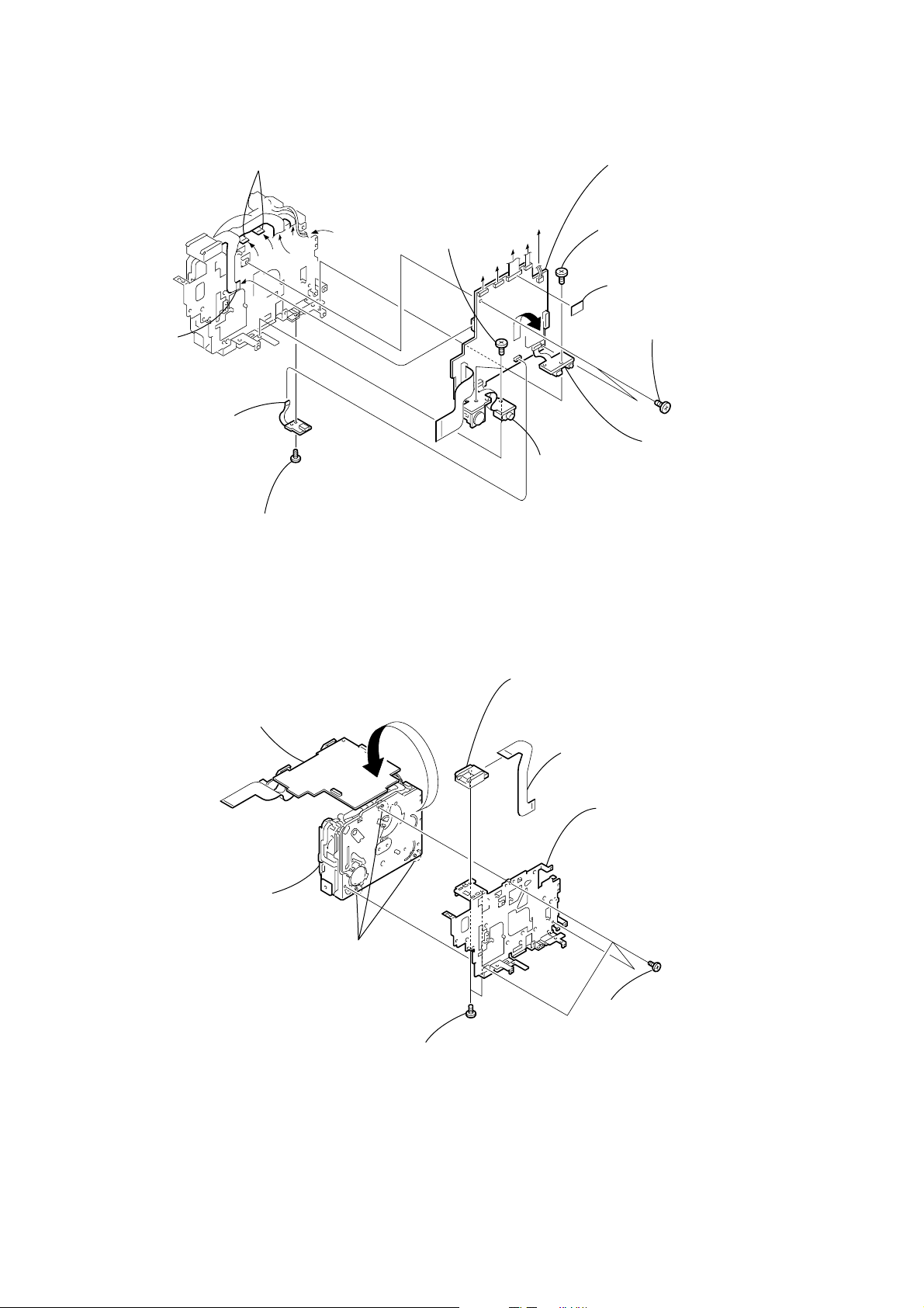
2-13. VC-262 BOARD
1
Remove the flexible boards
Remove the VC-262 board
qa
in the direction of the arrow
H
.
E
D
B
C
A
2
FP-264 flexible
board (15, 20P)
8
FP-332
board (6P)
9
Screw
(M1.7 × 2.5), p
2-14. MECHANISM DECK-2, MD FRAME (M)
4
Two screws
(M1.7
×
2.5), p
A
C
B
VC-262
Board
E
D
H
5
FP-270 board
6
Screw
(M1.7
3
VC sheet
×
2.5), p
0
Two screws
(M1.7
7
FP-272 board
×
2.5), p
1
Turn over VC-262 board
in the direction of the arrow.
4
Mechanism
deck
VC-262
Board
3
Three dowels
7
Two screws
(M1.7
×
2.5), p
8
External connector (hot shoe)
6
FP-264 flexible board
(15, 20P)
5
MD frame (M)
2
Three screws
(M1.7
×
2.5), p
— 18 —
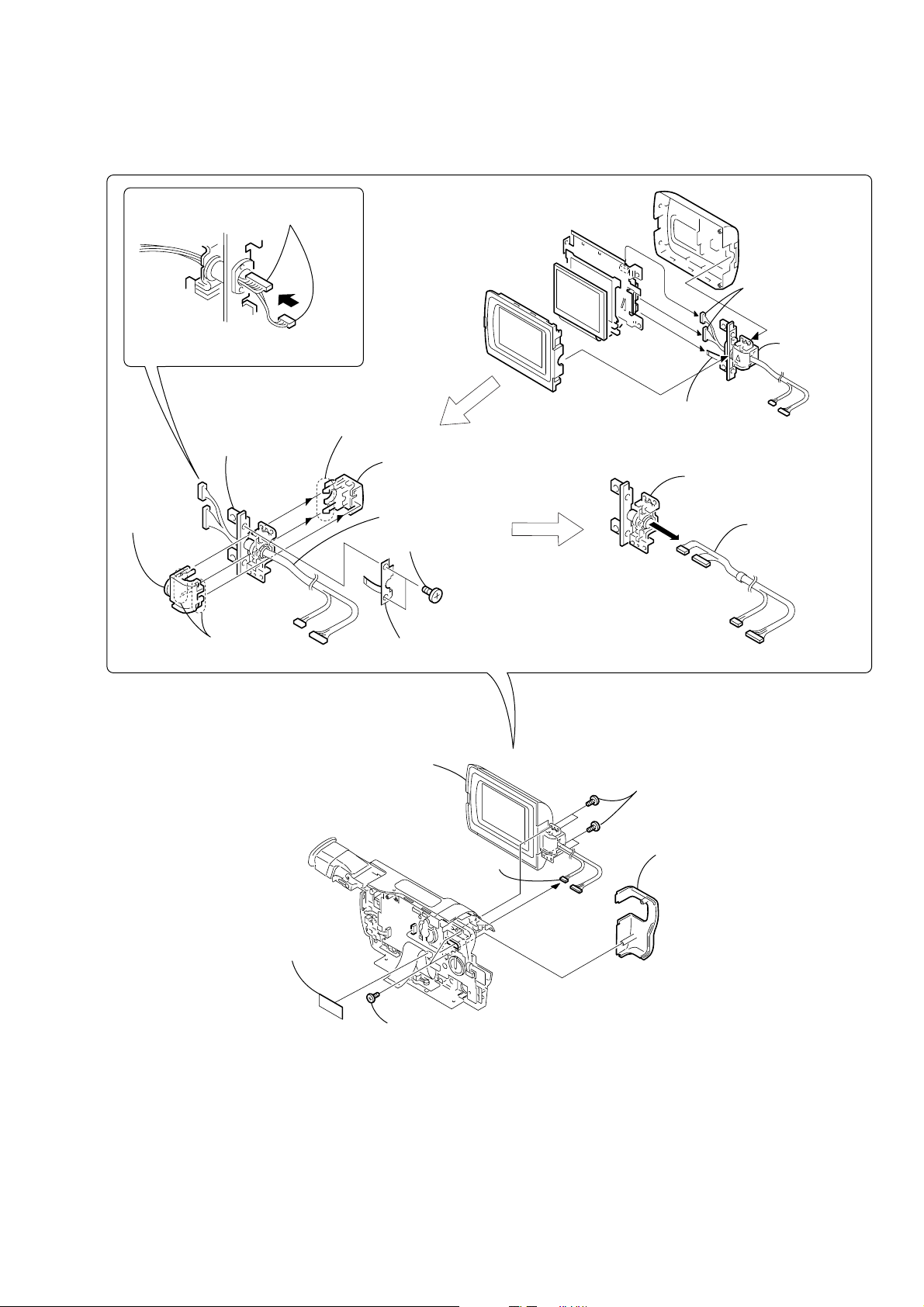
2-15. HINGE SECTION
REMOVING THE HINGE ASSEMBLY
Remove the Harness (VP-076) (6, 20P)
in the direction of the arrow A.
A
Then bend the harness so that it is laid
along with the connector.
7
Hinge
assembly
6
Hinge
cover (M)
3
Four claws
4
Two claws
5
Hinge cover C (M)
8
Harness (VP-076)
1
Two screws
(M1.7 × 2.5), p
2
FP-283 board
1
(VP-076)
(6, 20P)
2
FP-283
board (6P)
2
Hinge
assembly
Harness
3
1
Harness
(VP-076)
6
For removing the LCD unit
(See page 11, 12)
2
(VP-076) (6P)
CF-084
Board
1
Tape (A)
3
Two tapping
screws (B2 × 5)
Harness
5
Four tapping screws
(B2 × 5)
4
Hinge cover R (M)
— 19 —
3. REPAIR PARTS LIST
3-1. EXPLODED VIEWS
NOTE:
• -XX, -X mean standardized parts, so they may
have some differences from the original one.
• Items marked “*” are not stocked since they
are seldom required for routine service. Some
delay should be anticipated when ordering these
items.
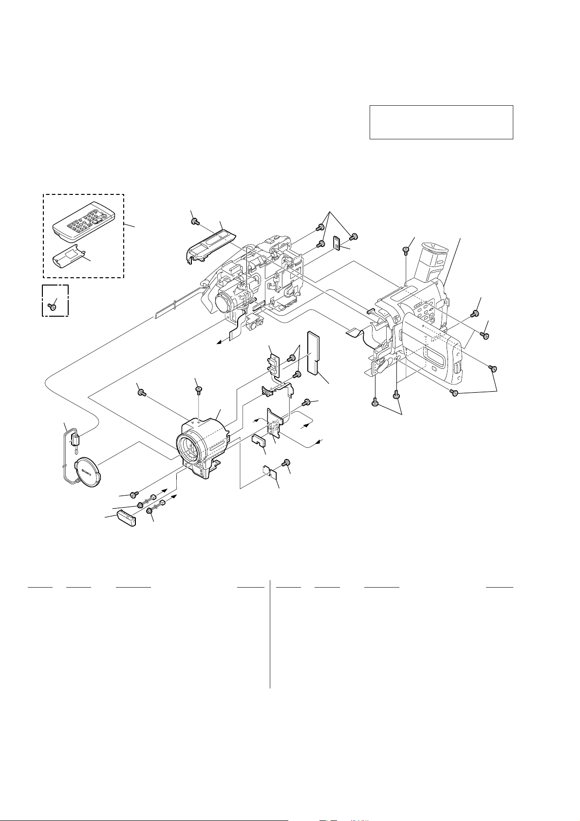
3-1-1. OVERALL SECTION
• The mechanical parts with no reference number
in the exploded views are not supplied.
The components identified by mark 0 or
dotted line with mark 0 are critical for safety.
Replace only with part number specified.
11
Screw fixing the printer
15
(PVP-MSH)
during transportation.
(TRV830E)
4
MIC902
1
3
13
12
3
Cabinet (R) section
(See page 23)
3
14
3
2
C
3
3
9
7
6
A
7
C
Digital 8
5
B
8
S
O
N
Y
3
3
10
B
3
MIC901
A
7
not supplied
Ref. No. Part No. Description Remarks Ref. No. Part No. Description Remarks
1 X-3951-161-1 GRILLE ASSY, MICROPHONE
2 3-065-567-01 TAPPING (M1.7)
3 3-067-347-01 MI SCREW M2 (H)
4 X-3949-376-1 CAP (N) ASSY, LENS
5 X-3951-496-1 PANEL ASSY (M), FRONT
6 3-066-720-01 CUSHION (SI)
7 3-948-339-61 TAPPING
8 not supplied SI-030 (GM) BOARD, COMPLETE
9 A-7074-651-A FP-273 BOARD, COMPLETE
10 3-065-327-01 CUSHION (MI)
11 3-742-854-01 LID, BATTERY CASE (FOR RMT-814)
12 1-475-141-61 REMOTE COMMANDER (RMT-814)
13 3-065-326-01 CABINET (UPPER)
14 3-065-325-01 LID(BT), CPC
15 3-989-134-01 SCREW (T), L LOCK (TRV830E)
MIC901 1-542-312-11 MICROPHONE (Lch)
MIC902 1-542-312-11 MICROPHONE (Rch)
— 20 —
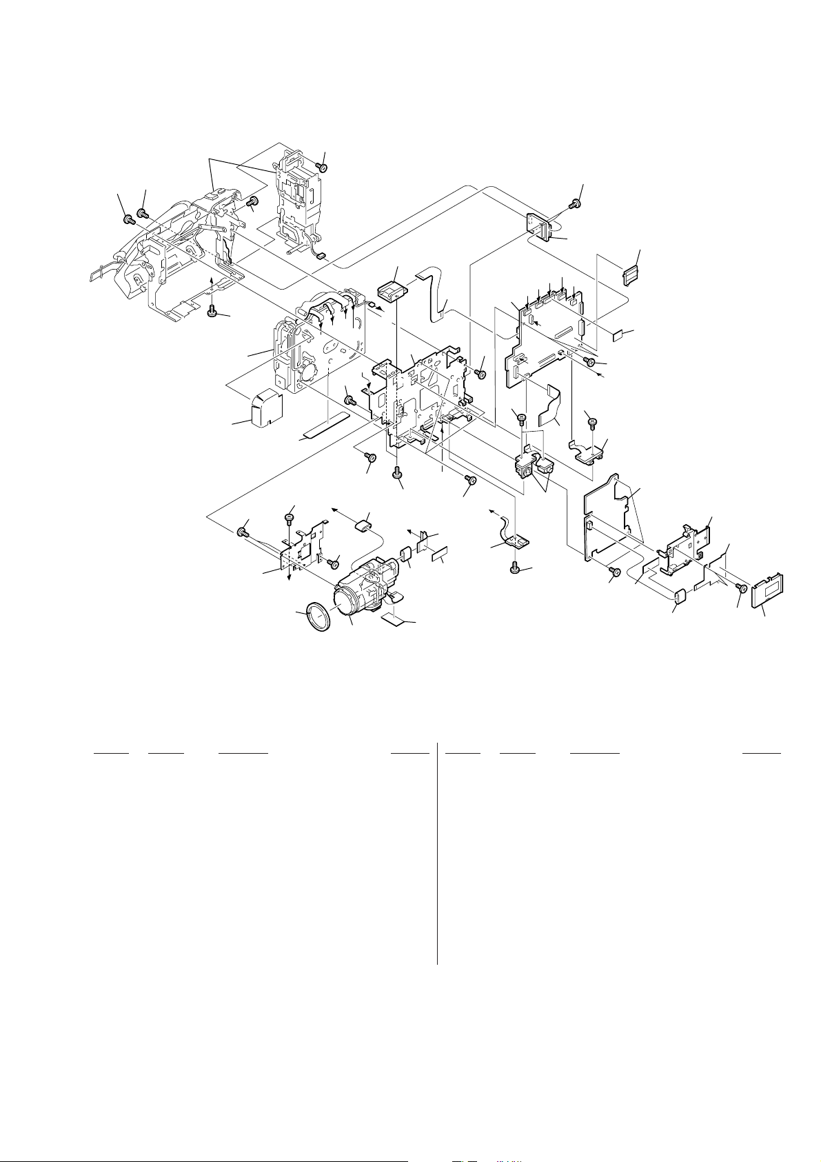
3-1-2. CABINET (L) SECTION-1
0
Cabinet (L) section-2
(See page 22)
75
65
Mechanism deck
C
65
68
not supplied
75
60
72
J
51
65
73
F
E
G
D
J
65
65
A
65
Lens section
(See page 25)
67
H
54
B
53
65
74
70
55
C
65
52
not
supplied
65
64
I
56
65
D
A
E
65
B
63
F
G
VC
Board
62
H
-262
57
65
65
M
M
Board
65
I
61
-043
65
70
69
71
66
74
58
59
60
CN91
Ref. No. Part No. Description Remarks Ref. No. Part No. Description Remarks
51 3-066-721-01 CUSHION, LENS
52 1-680-120-11 FP-317 FLEXIBLE BOARD
53 3-067-295-01 FRAME (M), MD
54 1-815-124-11 CONNECTOR, EXTERNAL (HOT SHOE)
55 1-680-118-11 FP-264 FLEXIBLE BOARD
56 not supplied VC-262 (GBPS) BOARD, COMPLETE (SERVICE)
57 not supplied FU-155 (GPF) BOARD, COMPLETE
58 3-067-285-01 HOLDER (M), MS
59 not supplied FP-319 FLEXIBLE BOARD
60 3-948-339-61 TAPPING
61 A-7074-650-A FP-272 BOARD, COMPLETE
62 1-680-122-11 FP-316 FLEXIBLE BOARD
63 A-7074-648-A FP-270 BOARD, COMPLETE
— 21 —
64 A-7074-763-A FP-332 BOARD, COMPLETE
65 4-974-725-01 SCREW (M1.7X2.5), P
66 not supplied MM-043 BOARD, COMPLETE
67 1-500-226-11 BEAD, FERRITE
68 3-066-169-01 SHEET, MD
* 69 X-3951-170-1 SHIELD ASSY, DD
70 3-941-343-21 TAPE (A)
71 3-066-759-01 SHEET, VC
72 3-065-662-01 LABEL, LS CAUTION
73 3-065-567-01 TAPPING (M1.7)
74 1-500-226-31 BEAD, FERRITE
75 3-067-347-01 MI SCREW M2 (H)
CN910 not supplied CONNECTOR, MEMORY STICK
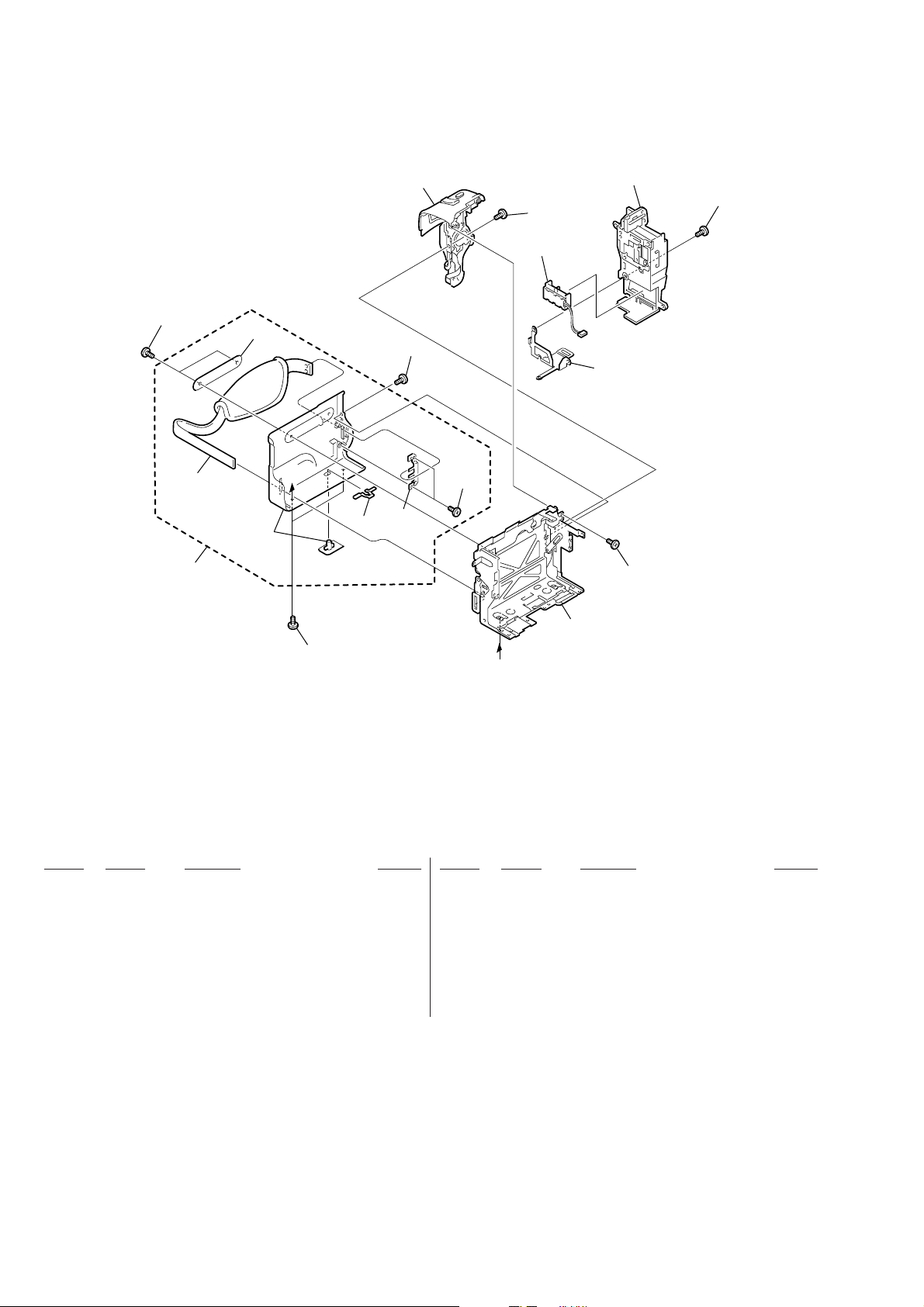
3-1-3. CABINET (L) SECTION-2
103
102
101
104
not
supplied
A
105
107
103
not
supplied
110
103
112
BT901
109
106
111
108
103
Ref. No. Part No. Description Remarks Ref. No. Part No. Description Remarks
101 X-3951-159-1 CABINET (L) ASSY
102 3-052-815-01 BELT (ES), GRIP
103 3-067-347-01 MI SCREW M2 (H)
104 3-065-308-01 LABEL (L)
105 3-978-765-01 SLIDER, G LOCK
106 3-713-791-01 SCREW (M1.7X4), TAPPING, P2
107 1-476-415-11 SWITCH BLOCK, CONTROL (SS-1380)
(TRV730E/TRV828E)
* 109 3-065-324-01 SHEET METAL (LOWER), STRAP
A
107 1-476-415-31 SWITCH BLOCK, CONTROL (SS-1380)
(TRV725E/TRV830E)
108 X-3951-495-1 FRAME ASSY (M), CS
110 X-3951-157-1 PANEL ASSY, BATTERY
111 3-065-567-01 TAPPING (M1.7)
112 4-974-725-01 SCREW (M1.7X2.5), P
BT901 1-694-772-11 TERMINAL BOARD, BATTERY
— 22 —
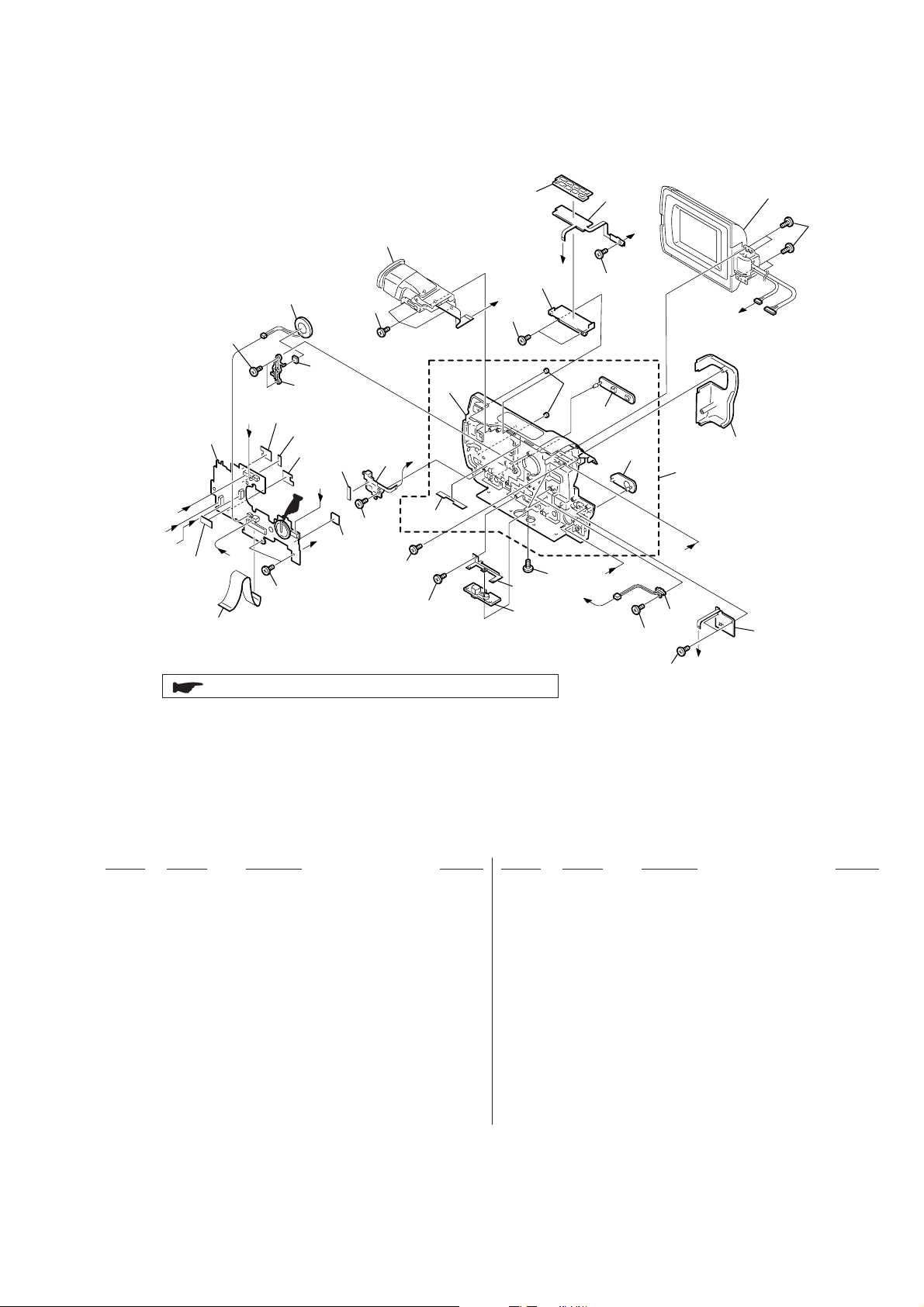
3-1-4. CABINET (R) SECTION
158
159
LCD section
(See page 24)
A
EVF section
(See page 25)
SP901
153
153
C
F
170
152
CF-084
Board
D
E
171
155
173
171
156
H
B
172
169
154
153
153
not
supplied
A
not
supplied
153
153
151
: BT101 (Lithium battery) CF-084 board on the mount position.
F
153
157
167
168
E
162
163
D
153
165
B
166
153
I
S910
153
153
C
161
164
I
160
H
Ref. No. Part No. Description Remarks Ref. No. Part No. Description Remarks
151 1-791-948-11 CABLE, FLEXIBLE FLAT (FFC-001)
152 not supplied CF-084 (SB) BOARD, COMPLETE
153 3-948-339-61 TAPPING
154 1-476-416-11 SWITCH BLOCK, CONTROL (SE-1380)
* 155 3-065-398-01 RETAINER, SPEAKER
* 156 3-058-658-01 SPACER (101), SPEAKER
157 3-067-272-01 HOLDER (M), VTR
158 3-067-271-01 BUTTON (M), VTR
159 A-7074-761-A FP-315 BOARD, COMPLETE
160 A-7074-762-A FP-318 BOARD, COMPLETE
161 3-067-301-01 COVER R (M), HINGE
162 3-067-347-01 MI SCREW M2 (H)
163 3-959-978-02 CUSHION, PANEL
164 X-3951-564-1 CABINET R (531) ASSY (TRV725E)
164 X-3951-565-1 CABINET (R) (531R) ASSY
(TRV730E/TRV828E/TRV830E)
165 3-065-353-01 COVER (B), JACK
166 3-065-352-01 COVER (F), JACK
167 3-067-273-01 RETAINER (M), TRIPOD
168 3-065-373-01 SCREW (Y), TRIPOD
* 169 3-065-521-01 SHEET, MUFFLE
170 3-941-343-21 TAPE (A)
171 3-067-824-01 SHEET (M1), CF ELECTROSTATIC
172 3-068-833-01 SPACER, CULUPON
173 3-067-825-01 SHEET (M2), CF ELECTROSTATIC
S910 1-771-848-11 SWITCH, PUSH
SP901 1-529-590-11 SPEAKER (2.0CM)
— 23 —
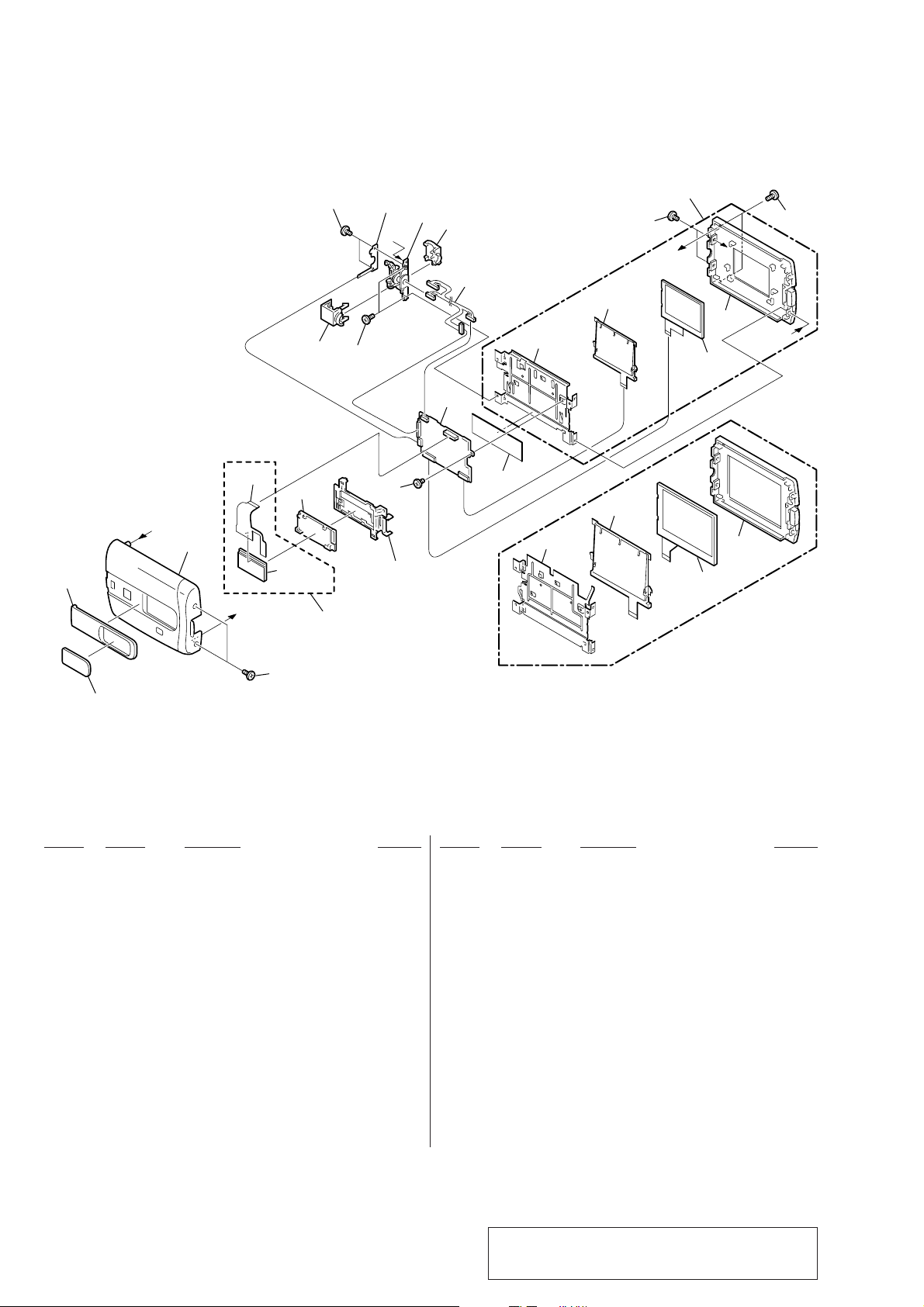
3-1-5. LCD SECTION
209
208
209
210
C
211
212
206
PD-139
Board
213
215
2.5 inch LCD model
(TRV725E/TRV730E)
217
A
ND901
207
C
216
B
LCD901
202
A
203
B
205
D902
not
supplied
217
209
not supplied
204
214
215
3.5 inch LCD model
(TRV828E/TRV830E)
ND901
216
LCD901
201
Ref. No. Part No. Description Remarks Ref. No. Part No. Description Remarks
201 3-065-366-01 WINDOW (2), LCD
202 X-3951-563-1 COVER (531) ASSY, CPC (TRV725E)
202 X-3951-566-1 COVER (531R) ASSY, CPC (TRV730E)
202 X-3951-568-1 COVER (541) ASSY, CPC (TRV828E)
202 X-3951-569-1 COVER (561) ASSY, CPC (TRV830E)
212 3-065-394-01 COVER (M), HINGE
213 1-960-973-21 HARNESS (VP-076)
214 3-067-283-01 SHEET (M), PD ELECTROSTATIC
215 3-067-277-01 FRAME (M2), P (TRV725E/TRV730E)
215 3-067-278-01 FRAME (M3), P (TRV828E/TRV830E)
203 X-3951-488-1 CABINET C (M) ASSY, P
204 not supplied INDICATION LCD (M) BLOCK ASSY (SERVICE)
205 not supplied FP-342 FLEXIBLE BOARD
206 not supplied PD-139 (Z12) BOARD, COMPLETE
(TRV828E/TRV830E)
206 not supplied PD-139 (X12) BOARD, COMPLETE
(TRV725E/TRV730E)
207 3-065-567-01 TAPPING (M1.7)
208 3-067-281-01 COVER C (M), HINGE
209 4-974-725-01 SCREW (M1.7X2.5), P
210 A-7074-654-A FP-283 BOARD, COMPLETE
211 X-3951-181-1 HINGE ASSY
— 24 —
216 X-3951-487-1 CABINET M (M) ASSY, P (TRV725E/TRV730E)
216 X-3951-561-1 CABINET (M) (M3) ASSY, P(TRV828E/TRV830E)
217 3-067-347-01 MI SCREW M2 (H)
0 D902 not supplied LIGHT, BACK
LCD901 not supplied ACX307AKC-J (SERVICE) (TRV725E/TRV730E)
LCD901 not supplied ACX310AK-J (SERVICE) (TRV828E/TRV830E)
0 ND901 not supplied TUBE, FLUORESCENT,COLD CATHODE
(TRV828E/TRV830E)
0 ND901 not supplied TUBE, FLUORESCENT,COLD CATHODE
(TRV725E/TRV730E)
Note : The components identified by mark 0 or dotted
line with mark 0 are critical for safety.
Replace only with part number specified.
Loading...