


 Loading...
DIGITAL FILM IMAGER
UP-DF750
SERVICE MANUAL Volume 1 1st Edition
!
! WARNING
This manual is intended for qualified service personnel only.
To reduce the risk of electric shock, fire or injury, do not perform any servicing other than that contained in the operating instructions unless you are qualified to do so. Refer all servicing to qualified service personnel.
! WARNUNG
Die Anleitung ist nur für qualifiziertes Fachpersonal bestimmt.
Alle Wartungsarbeiten dürfen nur von qualifiziertem Fachpersonal ausgeführt werden. Um die Gefahr eines elektrischen Schlages, Feuergefahr und Verletzungen zu vermeiden, sind bei Wartungsarbeiten strikt die Angaben in der Anleitung zu befolgen. Andere als die angegeben Wartungsarbeiten dürfen nur von Personen ausgeführt werden, die eine spezielle Befähigung dazu besitzen.
! AVERTISSEMENT
Ce manual est destiné uniquement aux personnes compétentes en charge de l’entretien. Afin de réduire les risques de décharge électrique, d’incendie ou de blessure n’effectuer que les réparations indiquées dans le mode d’emploi à moins d’être qualifié pour en effectuer d’autres. Pour toute réparation faire appel à une personne compétente uniquement.
つ可能性があるコネクターを以下のポートに接続しない でください。
:
For safety, do not connect the connector for peripheral device wiring that might have excessive voltage to the following port.
: Network connector (RJ-45)
Follow the instructions for the above port.
UP-DF750

必ず指定の電池に交換してください。
処理してください。
CAUTION
Danger of explosion if battery is incorrectly replaced. Replace only with the same or equivalent type recommended by the manufacturer.
When you dispose of the battery, you must obey the law in the relative area or country.
ATTENTION
Il y a danger d’explosion s’il y a remplacement incorrect de la batterie. Remplacer uniquement avec une batterie du même type ou d’un type équivalent recommandé par le constructeur.
Lorsque vous mettez la batterie au rebut, vous devez respecter la législation en vigueur dans le pays ou la région où vous vous trouvez.
VORSICHT
Explosionsgefahr bei Verwendung falscher Batterien. Batterien nur durch den vom Hersteller empfohlenen oder einen gleichwertigen Typ ersetzen.
Wenn Sie die Batterie entsorgen, müssen Sie die Gesetze der jeweiligen Region und des jeweiligen Landes befolgen.
FÖRSIKTIGHET!
Fara för explosion vid felaktigt placerat batteri. Byt endast mot samma eller likvärdig typ av batteri, enligt tillverkarens rekommendationer.
När du kasserar batteriet ska du följa rådande lagar för regionen eller landet.
PAS PÅ
Fare for eksplosion, hvis batteriet ikke udskiftes korrekt.
Udskift kun med et batteri af samme eller tilsvarende type, som er anbefalet af fabrikanten.
Når du bortskaffer batteriet, skal du følge lovgivningen i det pågældende område eller land.
HUOMIO
Räjähdysvaara, jos akku vaihdetaan virheellisesti. Vaihda vain samanlaiseen tai vastaavantyyppiseen, valmistajan suosittelemaan akkuun.
Noudata akun hävittämisessä oman maasi tai alueesi lakeja.
FORSIKTIG
Eksplosjonsfare hvis feil type batteri settes i. Bytt ut kun med samme type eller tilsvarende anbefalt av produsenten.
Kasser batteriet i henhold til gjeldende avfallsregler.
UP-DF750 |
1 (P) |
Table of Contents
Manual Structure
Purpose of this manual.................................................................. |
3 |
Related manuals............................................................................ |
3 |
Trademarks.................................................................................... |
3 |
1. |
Installation |
|
|
1-1. |
Operating Environment................................................... |
1-1 |
|
1-2. |
Outside Dimension Diagram........................................... |
1-2 |
|
1-3. |
Installation Space ............................................................ |
1-3 |
|
1-4. Caster (2T) Assembly Installation Procedure.................. |
1-3 |
||
1-5. |
Film Tray/Output Tray .................................................... |
1-5 |
|
1-6. |
Setting Procedure .......................................................... |
1-14 |
|
1-7. |
Film Loading Procedure................................................ |
1-15 |
|
1-8. |
DICOM Setting Method................................................ |
1-16 |
|
1-8-1. |
Preparation........................................................... |
1-16 |
|
1-8-2. |
Setup .................................................................... |
1-17 |
|
1-8-3. |
Modality ConnectionCustomizing....................... |
1-25 |
|
1-9. |
Check List ..................................................................... |
1-35 |
|
2. |
Service Overview |
|
|
2-1. |
Board Location................................................................ |
2-1 |
|
2-2. |
Main Parts Location ........................................................ |
2-4 |
|
2-3. Sensor/Actuator Location and Function.......................... |
2-7 |
||
2-4. |
Removing/Installing the Cabinet..................................... |
2-9 |
|
2-4-1. |
Front Sash (HR) Assembly .................................... |
2-9 |
|
2-4-2. |
MD Cover (BD)..................................................... |
2-9 |
|
2-4-3. |
Front Panel (L) (HR) Assembly........................... |
2-10 |
|
2-4-4. |
Front Panel (R) Assembly.................................... |
2-10 |
|
2-4-5. |
MD Front Panel Assembly/MD Upper Cover ..... |
2-11 |
|
2-4-6. |
Side Panel (L) ...................................................... |
2-13 |
|
2-4-7. |
Side Panel (R) ...................................................... |
2-13 |
|
2-4-8. |
Outer Frame L Cover........................................... |
2-14 |
|
2-4-9. |
Top Cover (D)...................................................... |
2-14 |
|
2-4-10. |
Rear Cover (TD)/PH2 Flap.................................. |
2-15 |
|
2-4-11. |
Rear Cover (Sub) ................................................. |
2-16 |
|
2-4-12. |
Rear Cover (BD).................................................. |
2-16 |
|
2-4-13. |
Side Panel (Sub)................................................... |
2-17 |
|
2-5. |
Optional Fixtures........................................................... |
2-18 |
|
2-5-1. |
Reference Sheet ................................................... |
2-18 |
|
2-5-2. |
Torque Driver Bit for M4 Setscrew ..................... |
2-18 |
|
2-6. |
Periodic Inspection........................................................ |
2-18 |
|
2-6-1. |
Cleaning of Main Unit ......................................... |
2-18 |
|
2-6-2. |
Tray Cleaning....................................................... |
2-20 |
|
2-6-3. |
Fan Filter.............................................................. |
2-20 |
|
2-6-4. |
Dust Cleaning Roller ........................................... |
2-20 |
|
2-6-5. |
Replacing the Periodic Replacement Parts .......... |
2-20 |
|
2-7. |
Maintenance Check....................................................... |
2-21 |
|
2-7-1. |
Preparation........................................................... |
2-21 |
|
2-7-2. |
Appearance Check ............................................... |
2-22 |
|
2-7-3. |
Check of Current Status....................................... |
2-22 |
|
2-7-4. |
Periodic Replacement Parts and Cleaning........... |
2-23 |
|
2-7-5. |
Version Upgrade and Virus Patch ........................ |
2-23 |
|
2-7-6. |
Confirmation ........................................................ |
2-23 |
|
2-8. |
Priority of Each Setting................................................. |
2-24 |
|
2-9. |
Servicing the CT-252 Board and MA-171 Board ......... |
2-24 |
|
2-10. |
Lead-free Solder............................................................ |
2-24 |
|
3. Replacing the Main Parts
3-1. |
Replacing the Board........................................................ |
3-1 |
|
3-1-1. |
MA-171 Board....................................................... |
3-1 |
|
3-1-2. |
DR-628 Board........................................................ |
3-4 |
|
3-1-3. |
KEY-61 Board/LE-356 Board/SW-1418 Board .... |
3-5 |
|
3-1-4. |
CN-3094 Board...................................................... |
3-6 |
|
3-2. |
MD (HR) Assembly ........................................................ |
3-7 |
|
3-3. |
PH1 (HR) Assembly........................................................ |
3-9 |
|
3-4. |
PH0 Assembly............................................................... |
3-11 |
|
3-5. |
PH2 Assembly............................................................... |
3-13 |
|
3-6. |
PH3 (HR) Assembly...................................................... |
3-15 |
|
3-7. |
Head Block (HR) Assembly.......................................... |
3-17 |
|
3-8. |
Thermal Head Assembly ............................................... |
3-19 |
|
3-9. |
Transfer Cleaning Roller............................................... |
3-23 |
|
3-10. |
Capstan B/Platen ........................................................... |
3-24 |
|
3-11. |
Rear Chassis Assembly ................................................. |
3-30 |
|
3-12. |
Base Chassis Assembly ................................................. |
3-32 |
|
3-13. |
Pinch Press Lever Assembly ......................................... |
3-33 |
|
3-14. |
Switching Regulator...................................................... |
3-34 |
|
3-15. |
DICOM BOARD .......................................................... |
3-36 |
|
UP-DF750 |
1 |
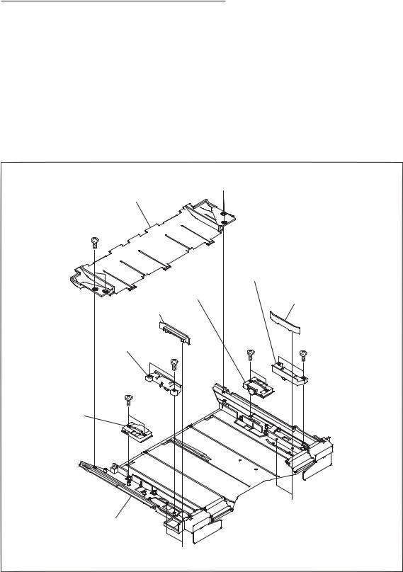
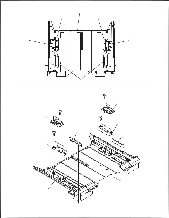
3-16. Paper Feed Chassis Assembly (Lower)......................... |
3-37 |
||
3-17. Paper Feed Chassis Assembly (Upper) ......................... |
3-40 |
||
3-18. Switching Regulator (For DICOM) .............................. |
3-42 |
||
3-19. |
Paper Feed Roller Assembly ......................................... |
3-43 |
|
3-19-1. |
Paper Feed Roller Assembly (Upper) .................. |
3-43 |
|
3-19-2. |
Paper Feed Roller Assembly (Lower).................. |
3-44 |
|
3-20. |
Separation Roller Assembly.......................................... |
3-45 |
|
3-21. |
Cleaning Roller ............................................................. |
3-46 |
|
3-22. |
Installing the Alternate Unit .......................................... |
3-47 |
|
4. Procedures after Replacement
4-1. |
Adjustment after Replacing the Thermal Head |
............... 4-1 |
|
4-1-1. |
Adjusting the Density ............................................ |
4-1 |
|
4-1-2. |
Adjusting the Head Position .................................. |
4-3 |
|
4-2. |
Procedures after Replacing the Board............................. |
4-5 |
|
4-2-1. |
MA-171 Board....................................................... |
4-5 |
|
4-2-2. |
CT-252 Board......................................................... |
4-6 |
|
4-2-3. |
SE-880 Board and SE-943 Board .......................... |
4-8 |
|
4-2-4. |
DICOM BOARD ................................................... |
4-8 |
|
4-3. |
Printing Position Adjustment Procedures........................ |
4-9 |
|
4-4. |
Operation List during Replacement of |
|
|
|
Main Assembly Parts..................................................... |
4-12 |
|
5. |
Circuit Description |
|
|
5-1. |
MA-171 Board ................................................................ |
5-1 |
|
5-1-1. |
Outline ................................................................... |
5-1 |
|
5-1-2. |
Configuration ......................................................... |
5-1 |
|
5-1-3. |
Digital Media Processors, FPGA, and |
|
|
|
|
Peripheral Circuits ................................................. |
5-2 |
5-1-4. |
USB Interface Block.............................................. |
5-3 |
|
5-1-5. |
Stepping Motor Controller Block and |
|
|
|
|
Sensor A/D Input Block......................................... |
5-3 |
5-1-6. |
Switches and LED Interface Block........................ |
5-3 |
|
5-1-7. |
LCD Interface Block.............................................. |
5-4 |
|
5-1-8. |
UART Block .......................................................... |
5-4 |
|
5-1-9. |
Control of Sensors and Switches ........................... |
5-4 |
|
5-2. |
DR-628 Board ................................................................. |
5-5 |
|
5-2-1. |
Outline ................................................................... |
5-5 |
|
5-2-2. |
Configuration ......................................................... |
5-5 |
|
5-3. |
CT-252 Board................................................................ |
5-18 |
|
5-3-1. |
Outline ................................................................. |
5-18 |
|
5-3-2. |
Configuration ....................................................... |
5-18 |
|
5-3-3. |
CPU and Its Peripheral Circuit ............................ |
5-18 |
|
5-4. DICOM BOARD .......................................................... |
5-20 |
|
5-4-1. |
Interface ............................................................... |
5-20 |
5-4-2. |
Functions.............................................................. |
5-20 |
6. |
Service Mode |
|
|
6-1. Service Mode Startup Method......................................... |
6-1 |
||
6-2. Basic Operation and Configuration of Menu .................. |
6-2 |
||
6-2-1. |
Information ............................................................ |
6-4 |
|
6-2-2. |
Print Quality........................................................... |
6-5 |
|
6-2-3. |
Calibration ............................................................. |
6-6 |
|
6-2-4. |
Default Gamma...................................................... |
6-7 |
|
6-2-5. |
Print Operation....................................................... |
6-8 |
|
6-2-6. |
System Settings...................................................... |
6-9 |
|
6-2-7. |
Test Print.............................................................. |
6-13 |
|
6-2-8. |
Test Print (Svc) .................................................... |
6-14 |
|
6-2-9. |
Manual Mecha ..................................................... |
6-15 |
|
6-2-10. |
Error Info ............................................................. |
6-18 |
|
6-2-11. |
Adjust................................................................... |
6-19 |
|
6-2-12. |
Self Check............................................................ |
6-21 |
|
6-2-13. |
Media (Tag) Menu ............................................... |
6-22 |
|
6-3. Firmware Version Upgrade Procedure .......................... |
6-23 |
||
6-3-1. |
Required Equipment ............................................ |
6-23 |
|
6-3-2. |
Version Upgrade Procedure ................................. |
6-23 |
|
6-3-3. |
Version Check...................................................... |
6-24 |
|
6-4. DICOM Version Upgrade Procedure ............................ |
6-24 |
||
6-4-1. |
Required Equipment ............................................ |
6-24 |
|
6-4-2. |
Version Upgrade Procedure ................................. |
6-24 |
|
6-4-3. |
Version Check...................................................... |
6-24 |
|
6-5. |
FilmStation Support Software....................................... |
6-25 |
|
6-5-1. |
Installation of FilmStation Support Software ...... |
6-25 |
|
6-5-2. |
How to use FilmStation Support Software .......... |
6-25 |
|
6-6. |
DICOM Virus Patch Method......................................... |
6-27 |
|
7. |
Troubleshooting |
|
|
7-1. |
Error Display................................................................... |
7-1 |
|
7-1-1. |
Error Display.......................................................... |
7-1 |
|
7-1-2. |
Error Message List................................................. |
7-2 |
|
7-1-3. |
Error History........................................................ |
7-11 |
|
7-2. |
Mechanical Troubleshooting......................................... |
7-14 |
|
7-3. |
Electrical Troubleshooting ............................................ |
7-18 |
|
7-3-1. |
Electrical Troubleshooting................................... |
7-18 |
|
7-3-2. |
Operation Defects of Motors and Sensors ........... |
7-19 |
|
2 |
UP-DF750 |

Manual Structure
Purpose of this manual
This manual is the Service Manual Vol.1 of the Digital Film Imager UP-DF750. This manual contains the installation, service overview, replacing the main parts, procedures after replacement, circuit description, service mode, and troubleshooting.
Related manuals
In addition to this Service Manual Vol.1, the following manuals are provided.
. Service Manual Vol.2
Contains the spare parts, block diagrams, schematic diagrams, and board layouts.
. Instruction for Use/Setup Manual
This manual describes the information required for the actual management and operation of this unit.
. “Semiconductor Pin Assignments” CD-ROM (Available on request)
This “Semiconductor Pin Assignments” CD-ROM allows you to search for semiconductors used in Broadcast and Professional equipment.
Part number: 9-968-546-06
Trademarks
Trademarks and registered trademarks used in this manual are as follows.
. Windows and Internet Explorer are registered trademarks of Microsoft Corporation in the United States and Other countries.
. Memory Stick and Memory Stick PRO Duo are trademarks of Sony Corporation.
Other system names, product names, and company names appearing in this manual are trademarks or registered trademarks of their respective holders.
UP-DF750 |
3 |
Section 1
Installation
m
. Keep the packing material because it is used for the transportation in servicing. When transporting this unit, remove the output tray tray and caster from this unit. Remove the film from the film tray 1 and film tray 2.
. When installing this unit, check the following setting items.
IP Address: |
Network setting |
Subnet Mask: |
Network setting |
Default Gateway: |
Network setting |
UP-DF750 installation location and space:
Location and power supply, network cable UP-DF750 carry-in route: Check of elevator, door, step, etc.
Size of film used
Attendance of Modality service personnel, or advance setting
1-1. Operating Environment
. Electric voltage: |
100 V AC to 120 V AC/200 V AC to 240 V AC, 50/60 Hz |
. Electric current consumption: |
4.4 A/2.4 A |
. Operation temperature: |
10 dC to 30 dC |
. Storage/transportation temperature: |
_20 dC to 60 dC |
. Storage/transportation humidity: |
20% to 80% |
. Maximum outside dimension: |
Approx. 600 x316 x686 mm |
(Width/height/depth) |
(Largest protrusion is not included.) |
. Mass: |
Approx. 65 kg |
UP-DF750 |
1-1 |

1-2. Outside Dimension Diagram
600
316 21
622
686
354
(When a caster is installed.) Unit: mm
1-2 |
UP-DF750 |
1-3. Installation Space
This unit can be installed in either horizontal or vertical direction. (Refer to Section 1-4.)
When installing, be sure to make space for the unit as shown in the right illustration.
Avoid installing this unit in the following places to prevent it from being damaged by foreign material, condensation, etc.
. Near the air exit of air conditioner
. Near the open window or door
. Near the busy passageway
. Places easily getting spattered with liquid
. Places being subjected by direct sunlight
Unit: mm
210
265
70
1-4. Caster (2T) Assembly Installation Procedure
This unit can be installed in vertical direction by attaching the supplied caster (2T) assembly.
m
. When attaching the caster (2T) assembly, be sure to work by two persons.
. Be sure to keep the four screws and four shoulder washers removed from the side panel (L).
. When attaching the caster (2T) assembly, make sure that there is no gap between the side panel (L) and front panel (L).
. When attaching the caster (2T) assembly, place the unit with the caster 2T sheet affixed surface facing downward.
. When installing this unit in vertical direction, it is recommended to place it with the left side facing downward.
. This unit is differently controlled depending on the direction it is installed; horizontal direction, vertical direction with right side down or left side down. The sensor can detect the difference between vertical and horizontal direction. But it cannot detect the difference between right and left when the unit is installed in vertical direction. Therefore, the setting is performed on the service mode. (Section 6-2-6, System Setting → Setting Position)
. When attaching the caster (2T) assembly, be sure to use the supplied stopper sheet. (Refer to the instruction manual for the usage.)
UP-DF750 |
1-3 |

1.Remove the four screws (RK4 x8) and four shoulder washers from the side panel (L) and side panel (sub).
2.Attach the caster (2T) assembly using the four screws (B4 x16).
Side panel (L)
Shoulder washers
RK4 x 8 
Side panel (sub)
Side panel (L)
B4 x 16
Caster (2T) assembly
Caster 2T sheet |
B4 x 16 |
|
Caster (2T) assembly
Space
Front panel (L)
Caster 2T sheet
1-4 |
UP-DF750 |
1-5. Film Tray/Output Tray
m
. The lower tray and upper tray have the stopper for preventing mis-insertion. Therefore, do not push the tray forcefully.
. Do not load the film of size that is different from the internal film position guide setting. Otherwise, it may cause a jam or a serious trouble due to malfunction.
. Both upper tray and lower tray support all the following film sizes. 8 x10 inch (UPT-510BL/UPT-M710BL)
10 x12 inch (UPT-512BL/UPT-M712BL)
11 x14 inch (UPT-514BL)
14 x17 inch (UPT-517 BL)
. The factory-installed film trays are as follows. Upper tray: 14 x17 inch
Lower tray: 8 x10 inch
When using the tray size (10 x12 inch, 11 x14 inch) other than the above, use the supplied film size change kit for the upper tray. As for the lower tray, move the film position guide.
. No operation is required for the film size because it is automatically recognized by the IC tag.
. In the case of using the film size of 10 x12 inch or 8 x10 inch, attach the output tray stopper.
Film tray
Film size changing method
Upper tray:
Use the supplied film size change kit.
Lower tray:
Change the size as follows.
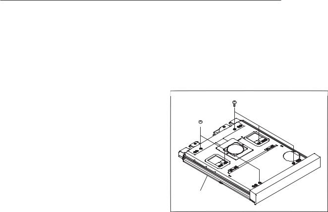
1.Remove the six screws with the tray cover facing downward.
BTP 3 x 10
BTP 3 x 10 
Film tray
UP-DF750 |
1-5 |
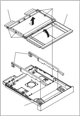
2.Open the tray cover (front) in the direction of the arrow with the tray cover facing upward.
3.Pull the rear (SH) cover once in the direction of the arrow and remove the six hooks, and then lift up and remove the rear (SH) cover.
4.Remove the film position guide.
5.Align the film position guide with the size position of the film used.
Hooks
Rear (SH) cover
Tray cover (front)
Hooks
Film position guides (side)
Film position guide (front)
1-6 |
UP-DF750 |
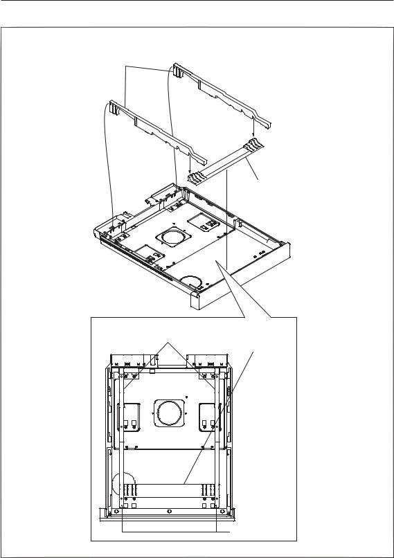
11 x14 inch
Film position guides (side)
Film position guide (front)
Film position
guides (side) Film position guide (front)
11 x 14 inch
6. To install, reverse the removal procedure.
UP-DF750 |
1-7 |

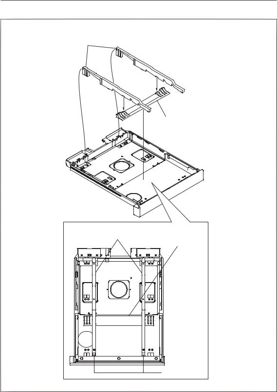
10 x12 inch
Film position guides (side)
Film position guides (side)
6. To install, reverse the removal procedure.
Film position guide (front)
Film position guide (front)
10 x 12 inch
1-8 |
UP-DF750 |
8 x10 inch
Film position guides (side)
Film position guides (side)
6. To install, reverse the removal procedure.
Film position guide (front)
Film position guide (front)
8 x 10 inch
UP-DF750 |
1-9 |

Output tray
m
. Depending on the combination of the film size, it is required to change the configuration of output tray.
. Factory setting is the large size.
. When installing the output tray, securely push it as far as it will go. For more details, refer to the Instruction for Use.
Large size
In the combination of the following film size, it is not required to change the tray installed at the factory. Use the supplied stopper for output tray. The stopper for output tray is used to prevent the film ejected in the upper output tray from going into backward and being difficult to be taken out.
Combination of film size |
Output tray stopper |
|
8 x10 |
8 x10 |
Required |
8 x10 |
10 x12 |
|
|
|
|
8 x10 |
14 x17 |
|
|
|
|
10 x12 |
10 x12 |
|
10 x12 |
14 x17 |
|
11 x14 |
11 x14 |
Not required |
|
|
|
11 x14 |
14 x17 |
|
|
|
|
14 x17 |
14 x17 |
|
n
When using the 11 x14 inch size film, the stopper for output tray may cause the film jamming.
Stack assist |
Stack assist |
|
(14 inch paper |
||
(14 inch paper |
||
eject detection) |
||
eject detection) |
||
|
||
Stack assist 2 |
Stack assist 2 |
|
(11 inch paper |
||
(11 inch paper |
||
eject detection) |
||
eject detection) |
||
|
Guide 10 x 12
1-10 |
UP-DF750 |
Small size
In the combination of the following film size, it is required to change the tray installed at the factory. Use the supplied stopper for output tray. The stopper for output tray is used to prevent the film ejected in the upper output tray from going into backward and being difficult to be taken out.
Combination of film size |
Output tray stopper |
|
8 x10 |
11 x14 |
Required |
10 x12 |
11 x14 |
|
|
|
|
Changing from large size to small size
1.Remove the four screws, then remove the output tray rear. n
Keep the removed output tray rear.
2.Remove the four screws, then remove the two stack assists.
3.Remove the four screws, then remove the two stack assists 2.
4.Remove the four screws, then remove the two guides 10 x12.
 B2.6 x 6
Output tray rear
B2.6 x 6
Stack assist
Guide 10 x 12
Stack
assist 2
B2.6 x 6
B2.6 x 6
Stack assist
Film tray
B2.6 x 6 
Stack assist 2
Guide 10 x 12
B2.6 x 6 |
B2.6 x 6 |
 B2.6 x 6
UP-DF750 |
1-11 |
5.Attach the two stack assists 2 to the position with the four screws.
6.Attach the two stack assists to the position with the four screws.
7.Attach the two guides 10 x12 to the position with the four screws.
Output tray stopper
Stack assist 2 Stack assist 2
Stack assist |
|
|
Stack assist |
|
|
|
|||
|
|
|
Guide 10 x 12 |
|
B2.6 x 6 |
|
Stack assist |
|
B2.6 x 6 |
Stack assist |
B2.6 x 6 |
|
|
|
Stack assist 2 |
|
Guide |
B2.6 x 6 |
10 x 12 |
Guide 10 x 12 |
|
Stack assist 2 |
|
 B2.6 x 6
Output tray
B2.6 x 6 
1-12 |
UP-DF750 |
8. Attach the output tray stopper with the two nylon rivets.
Output tray stopper
Output tray
Nylon rivets
UP-DF750 |
1-13 |
1-6. Setting Procedure
Each setting is as follows.
1. Power On
Check that the system starts after turning on the power, then enter the service mode. (Refer to Section 6-1.)
When performing the setting copy using Memory Stick, execute the System Settings → Memory Card → Load Settings. (Refer to Section 3-22.)
2. Network setting
Perform the network setting such as an IP address via PC or by System Settings. For more details of System Settings, refer to Section 6-2-6.
3. Film loading
1.Load the film in the upper tray and lower tray.
2.Check that the film size and the number of remaining sheets are displayed on the LCD panel.
n
If Tag Mismatch is displayed, the specifications of UP-DF750 do not check to those of the film. Contact your local Sony Sales Office/Service Center.
4. Calibration
Perform calibration for each film and check that LCD becomes READY state. n
If the CAL automatic correction cannot be performed, NG is displayed.
The film can be used without calibration because it is adjusted to specified density.
Perform calibration in the following cases. In addition to the manual calibration, it is possible to set the unit so that the first sheet can be automatically calibrated when new film is loaded. For more details, refer to Section 6-2-3.
. Accurate density control is required.
. The unit is used under the environment where temperature or humidity changes greatly. Perform calibration as required when the print density does not seem to meet the gamma setting.
5. Printing from Modality
After checking the setting of UP-DF750 of Modality, perform the printing from Modality. Check the items below.
. Film size setting
. Max Density and Min Density setting
. AE title name
. Configuration Information setting
. 604DPI/resize (Magnification Type) setting n
When changing the connection with the modality, refer to Section 1-8-3.
6. Gamma setting
When the gamma data is available in advance, setting is performed by FSSS. (Refer to Section 6-5.) If the gamma is specified by Default, change the setting of the main unit. (Refer to Section 6-2-4.)
1-14 |
UP-DF750 |
7. Gamma check and approval
Print out the image specified by the user and get the approval of density setting from the responsible person.
n
If requested by the user, adjust the gamma curve using FSSS. The selection of gamma can be performed by the default setting, Modality ConnectionCustomizing (Refer to Section 1-8-3.) or Configuration Information setting of modality. In the service mode (Refer to Section 6-1.), the selected gamma is indicated as G=x in the lower area of the printed output. So it can be checked. Be sure to perform calibration before printing the image for obtaining the approval of gamma. (Refer to Section 6-2-3.)
8. Check other setting
As for Frame Type, the image frame can be enlarged. The density in the edge of film is not uniform, therefore the image quality of the area outside of the specified size (Caption 2) of each film is not assured. In the case of changing the setting, explain users about this. The factory setting is as follows.
System Settings menu |
|
. Dither: |
ON |
. Mirror: |
OFF |
. L/R Mark: |
OFF |
. Frame Type: |
Caption2 |
. Caption Upper: |
ON (No data) |
Lower: |
OFF (No data) |
. Film Empty Buzzer: |
OFF |
. Setting Position: |
Horizontal |
Calibration menu
. Auto Calibration setting: OFF
1-7. Film Loading Procedure
n
. Handle the film wrapped by the moisture-proof bag with both hands. The contamination on the film surface such as fingerprint and sweat may cause degradation of the printed image quality. Be careful not to touch the print surface.
. When handling the output tray, firmly hold the side of the tray and tray cover.
UP-DF750 |
1-15 |

1-8. DICOM Setting Method
1-8-1. Preparation
This section gives the system administrator information needed to setup the unit on a network, to reset the IP address, to custmize the connection with modality and so on.
And describes the preparation required for the setup, gives an overview of the setup window, explains how to perform the setup related to the IP address, and so on. It also explains how to setup an E-mail warning to notify you automatically and to check the condisition of this unit via a network when any trouble occurs.
Required equipment
. Personal Computer (PC): LAN interface equipped
. Operating system: Microsoft Windows 2000, or Windows XP/Vista
. LAN cable (cross)
. Web browser software: Internet Explorer 6.0 or later
Settings of the Web browser software
Set the Web browser software as follows:
. No proxy
. A blank page is opened when the Web browser software is started.
IP Address
When you use the unit for the first time immediately, it is necessary to set up the DICOM part placed inside the unit, adding an IP address and so on.
Before starting the setup, check the following with the network administrator.
. The IP address this unit will use on the network
. Sub-net mask of the network
. Gateway address, if a gateway is included in the network
To check the IP address
The IP address assigned to this unit can be checked.
1.Turn on the power of this unit.
2.Strat the service mode. (Refer to Section 6-1.)
3.Open the Information menu to check IP address. (Refer to Section 6-2-1.)
1-16 |
UP-DF750 |

1-8-2. Setup
Preparation
1.Start the PC to be used for setup.
2.Open the TCP/IP setting page.
3.Enter the following IP address of the computer and the sub-net mask. IP address of the computer: NNN.NNN.NNN.nnn
NNN.NNN.NNN: Use the same numbers as those of the IP address assigned to this unit on the network from the first NNN to the third NNN.
nnn:Use any numbers from 1 to 254. However, you should not use the same numbers as the numbers of the fourth NNN of the IP address of this unit.
n
NNN.NNN.NNN.NNN: IP address assigned to this unit on the network
Sub-net Mask: 255.255.255.0
4.Restart the PC.
5.Connect this unit and the PC to be used for setup using the network cross cable.
About the setup/status window
This unit can be set up on the setup/status window displayed on the Web browser. The setup/status window has the following pages:
Status window http://NNN.NNN.NNN.NNN
. Summary/Print Job page
Displays the summary and print job status of this unit.
. Printer Status page
Displays the status of this unit.
Setup window http://NNN.NNN.NNN.NNN/PrinterSetup
. Local Settings page
Sets up the IP address, DICOM Local AE title, and so on.
. E-Mail Settings page
Sets up the items related to E-Mail.
ConnectivityCustomizing page http://NNN.NNN.NNN.NNN/PrinterSetup/PrinterSetup.exe/ConnectivityCustomizing Set up the connection with the modality.
n
. When the username and password is required, contact your local Sony Sales Office/Service Center.:
. NNN.NNN.NNN.NNN: IP address assigned to this unit.
UP-DF750 |
1-17 |

Opening the window
1.Start the PC to be used for setup, and then start the Web browser software.
2.Enter the URL for the window to display. NNN.NNN.NNN.NNN: IP address assigned to this unit.
Page selection area
3. Click the desired page in the page selection area.
1-18 |
UP-DF750 |

Network setup
Perform the following settings when the unit is used for the first time, or when the IP address assigned to this unit is changed.
Procedure
1.Enter “http://NNN.NNN.NNN.NNN/PrinterSetup” to open the Local Settings page. n
When the username and password is required, contact your local Sony Sales Office/Service Center.:
2.Perform the required settings related to TCP/IP.
IP Address text box
Sub-net Mask text box Default Gateway text box
(1)Enter the IP address of this unit on the network in the IP Address text box.
(2)Enter the sub-net mask in the Sub-net Mask text box.
(3)Enter the IP address of the default gateway in the Default Gateway text box if a gateway is used on the network.
3.Enter the DICOM Local AE title in the AE Title text box.
Up to 16 characters can be entered. n
When Local AE Title is not blank and its setting is different from Called AE title, Association is rejected. Blank is recommended.
AE Title text box
4.Click the [Save|settings] button. The settings are saved.
UP-DF750 |
1-19 |

1. Summary/Print Job page
This page displays information on this unit.
|
|
|
Printer (printer status) display section
Printer Status: Displays the printer status.
Upper Tray Status: Indicates the status of film sheets loaded in film tray 1. OK: Correct
Set Films/Papers...: Film sheets are not loaded. Set Film/Paper Tray...: Film tray 1 is not inserted.
Lower Tray Status: Indicates the status of film sheets loaded in film tray 2. OK: Correct
Set Films/Papers...: Film sheets are not loaded. Set Film/Paper Tray...: Film tray 2 is not inserted.
Upper Tray Media: Displays the type of blue thermal film loaded in film tray 1. Lower Tray Media: Displays the type of the blue thermal film loaded in film tray 2.
Print Job List display section
Displays when a job is waiting to be printed.
Add test pattern to print job (for the default tray only)
Click this link to print the test pattern. The film sheets loaded in film tray 1 is used for this printing.
Refresh button
Click this button to refresh the window.
1-20 |
UP-DF750 |

2. Printer Status Page
This page displays the status of this unit.
Upper Tray display area
Film/Paper Tray: |
Displays whether or not film tray 1 is inserted. |
Films/Papers: |
Displays whether or not film sheets are loaded in film tray 1. |
Film/Paper Output: |
Displays the status of the film output slot. |
Tag: |
Displays the confirmability status of the IC tag of the film sheets loaded in |
|
the film tray 1. |
Media Type: |
Displays the type of the film sheets loaded in film tray 1. |
Media Size: |
Displays the size of the film sheets loaded in film tray 1. |
Film/Papers Remaining: Displays the remaining amount of film sheets in film tray 1.
UP-DF750 |
1-21 |
Lower Tray display area
Film/Paper Tray: |
Displays whether or not film tray 2 is inserted. |
Films/Papers: |
Displays whether or not film sheets are loaded in film tray 2. |
Film/Paper Output: |
Displays the status of the film output slot. |
Tag: |
Displays the confirmability status of the IC tag of the film sheets loaded in |
|
film tray 2. |
Media Type: |
Displays the type of the film sheets loaded in the film tray 2. |
Media Size: |
Displays the size of the film sheets loaded in film tray 2. |
Film/Papers Remaining: Displays the remaining amount of film sheets in the film tray 2. |
|
Printer Status display area |
|
Motor/Sensor: |
Displays the error status of the motor/sensor system. |
Film /Paper Path: |
Displays the status of the printing path. |
Cover: |
Displays the status of covers (opened or closed). |
Printer Engine Status: Displays the printer operating status (idling, printing and so on)
Printer Statistics display area
Displays the total printings performed by the unit.
Print count with the current thermal head: Displays the total prints after the thermal head has been
|
replaced. |
Lifetime print count: |
Displays the total prints since the unit has been shipped. |
Printer Information display area
Vendor ID, Model Name, Version Number, Resolution: Displays various information on the unit
status.
[Refresh|button]
Click this button to refresh the window.
1-22 |
UP-DF750 |
Loading...