


A-BVP-100-11 (1)
Color Digital Camera
Technical Manual
DFW-SX910/X710
2004 Sony Corporation

Table of Contents |
|
Overview |
|
Main Features ............................................................ |
3 |
System Components................................................. |
5 |
Connection Diagram ................................................. |
6 |
Location of Parts and Operation .............................. |
7 |
Functions |
|
IIDC Standard Features ............................................. |
8 |
Brightness .................................................................. |
8 |
Auto Exposure ............................................................ |
8 |
Sharpness .................................................................. |
8 |
White Balance ............................................................ |
8 |
Hue ............................................................................. |
8 |
Saturation ................................................................... |
8 |
Gamma....................................................................... |
9 |
Shutter ........................................................................ |
9 |
Gain .......................................................................... |
10 |
Trigger Shutter .......................................................... |
10 |
Pan/Tilt ..................................................................... |
11 |
Optical Filter ............................................................. |
11 |
Memory Channels .................................................... |
11 |
Partial Scan .............................................................. |
12 |
IIDC Extended Features .......................................... |
13 |
Memory Shot ............................................................ |
13 |
PAINT ....................................................................... |
14 |
User Memory Area ................................................... |
14 |
Non-IIDC Features ................................................... |
14 |
1394 Bus Synchronization........................................ |
14 |
Exposure Out ........................................................... |
14 |
Control |
|
Camera Command Status Register ....................... |
15 |
Memory Map ............................................................ |
15 |
ConfigROM ............................................................... |
16 |
Control Base Address ............................................. |
18 |
Verifying Supported Video Modes ......................... |
18 |
Video Mode Settings ............................................... |
20 |
Starting/Stopping VideoTransfer (Continuous Shot).. |
20 |
One Shot and Multi Shot......................................... |
20 |
Memory Channel Operation ................................... |
21 |
Feature Controls (Complies with the IIDC Standard) .. |
22 |
Feature Controls (IIDC Extended) .......................... |
27 |
PAINT Control........................................................... |
28 |
Memory Shot Control ............................................... |
28 |
User Memory Control ............................................... |
28 |
Partial Scan Operations .......................................... |
29 |
Appendix |
|
Notes on the Camera Operations .......................... |
32 |
Timing Between External Trigger Signal and Video |
|
Signal Output ........................................................ |
34 |
Specifications .......................................................... |
35 |
CCD Pixel Location (Top View) ............................... |
39 |
Spectral Sensitivity (Relative Response) |
|
Parameters ............................................................ |
40 |
Dimensions .............................................................. |
41 |
DFW-SX910/X710 |
2 |

Overview
Overview
The DFW-SX910 with its 1/2-type PS IT CCD, and the DFW-X710 with its 1/3-type PS IT CCD are highresolution industrial-use digital video camera modules. The IEEE1394–1995 digital interface realizes a transfer speed of 400 Mbps and outputs SXGA (1280 × 960)/YUV (4:2:2)/7.5 fps with the DFW-SX910, XGA (1024 × 768)/YUV (4:2:2)/15 fps with the DFWX710. In addition, the DFW-SX910/X710 also adopts a primary color filter CCD to realize good color reproducibility, as well as a square pixel CCD to eliminate the need for aspect ratio conversion in the image processor.
What is the IEEE1394?
The IEEE1394 is the standard serial bus for sending and receiving digital data. It is prescribed as “IEEE* Std. 1394-1995 IEEE Standard for a High Performance Serial Bus.”
The most outstanding feature of this interface is that it realizes transfer speeds of up to 400 Mbps and can handle large image data size. The interface is also capable of “Isochronous transmission” which transmits data real-time, for up to 64 channels. Connectors can be inserted and disconnected while the unit is turned on, and no terminators and no ID settings such as those necessary for the SCSI interface are required.
* The Institute of Electrical and Electronics Engineers, Inc.
Main Features
The DFW-SX910 video camera module utilizes a 1/2-type PS IT CCD, and the DFWX710 utilizes a 1/3-type PS IT CCD
High-speed digital interface IEEE1394
The transmission speed is 400 Mbps. The DFWSX910 can output a digital image at 7.5 frames per second; the DFW-X710 can output a digital image at 15 frames per second.
High-resolution
The DFW-SX910 (SXGA) has a high-resolution CCD of 1.45 million pixels. The DFW-X710 (XGA) has a high-resolution CCD of 800,000 pixels. Because the CCDs are square pixel CCDs, you don’t need to convert the aspect ratio in your image processing.
External trigger function
The external trigger shutter function allows the image exposure to be coordinated with external equipment and moving objects.
For exposure time, the unit is equipped with Trigger Mode 0, which indicates the length of the exposure using the shutter parameter, and Trigger Mode 1, which controls exposure time by the width of the trigger signal.
It is also able to utilize a software trigger initiated by a command from a program running on a host computer.
DFW-SX910/X710 |
3 |

Overview
Partial scan output image format
You can select and output any rectangle part from a full-size image. This allows you to efficiently capture images at a faster frame rate.
C-mount
Non-compressed YUV4:1:1/ YUV4:2:2/
Mono8 (8 bits each)
Solid aluminum diecast chassis
DFW-SX910/X710 |
4 |
Overview
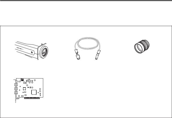
System Components
The DFW-SX910/X710 Video Camera Module system comprises the following components.
|
|
|
|
|
|
|
|
|
|
|
|
|
|
|
|
|
|
|
|
|
|
C-mount Lens |
|
|
|
|
|
|
|
|
|
|
|
|
|
|
|
|
|
|
|
|
|
|
|
|
Video Camera Module |
IEEE1394 Cable |
J6 × 11 MACRO (Canon) |
|||||||||||||||||||
|
(6-pin, 4.5 m) |
25MM HD LENS VF2509 (Canon) |
||||||||||||||||||||
|
DFW-SX910/X710 |
|
|
|||||||||||||||||||
|
|
|
|
|
|
|
|
|
|
|
|
|
|
|
|
|
|
|
|
|
|
|
|
|
|
|
|
|
|
|
|
|
|
|
|
|
|
|
|
|
|
|
|
|
|
|
|
|
|
|
|
|
|
|
|
|
|
|
|
|
|
|
|
|
|
|
|
|
|
|
|
|
|
|
|
|
|
|
|
|
|
|
|
|
|
|
|
|
|
|
|
|
|
|
|
|
|
|
|
|
|
|
|
|
|
|
|
|
|
|
|
|
|
|
|
|
|
|
|
|
|
|
|
|
|
|
|
|
|
|
|
|
|
|
|
|
|
|
|
|
|
|
|
|
|
|
|
|
|
|
|
|
|
|
|
|
|
|
|
|
|
|
|
|
|
|
|
|
|
|
|
|
|
|
|
|
|
|
|
|
|
|
|
|
|
|
|
|
|
|
|
|
|
|
|
|
|
|
|
|
|
|
|
|
|
|
|
|
|
|
|
|
|
|
|
|
|
|
|
|
|
|
|
|
|
|
|
|
|
|
|
|
|
|
|
|
|
|
|
|
|
|
|
|
|
|
|
|
|
|
|
|
|
|
|
|
|
|
|
|
|
|
|
|
|
|
|
|
|
|
|
|
|
|
|
|
|
|
|
|
|
|
|
|
|
|
|
|
|
|
|
|
|
|
|
|
|
|
|
|
|
|
|
|
|
|
|
|
|
|
|
|
|
|
|
|
|
|
|
|
|
|
|
|
|
|
|
|
|
|
|
|
|
|
|
|
|
|
|
|
|
|
|
|
Host Adapter Card (Commercially available)
DFW-SX910/X710 |
5 |
Overview
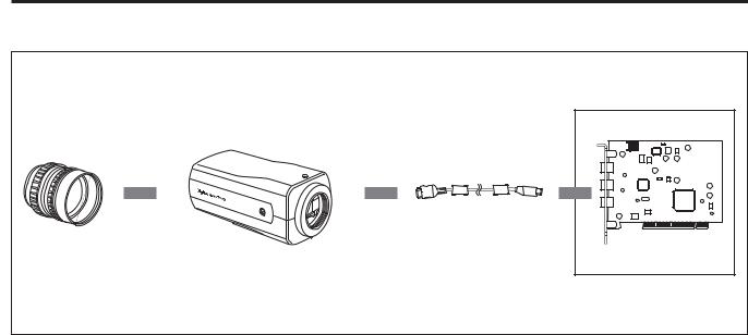
Connection Diagram
C-mount Lens |
DFW-SX910/X710 |
IEEE1394 Cable
Recommended Lens:
J6 × 11 MACRO (Canon) 25MM HD LENS VF2509 (Canon)
Host Adapter Card |
Host Equipment (PC, etc.)
DFW-SX910/X710 |
6 |
Overview
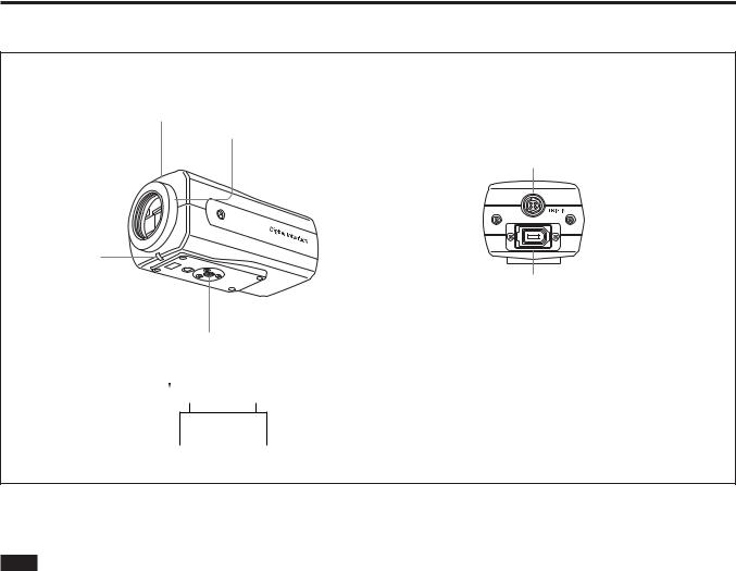
Location of Parts and Operation
Front/Top/Bottom |
Rear Panel |
2
1
5
3
6
4
2 

 1
1
1 Lens mount (C-mount)
Attach any C-mount lens or other optical equipment.
Note
The lens must not project more than 7 mm (9/32 inch) from the lens mount.
1 Lens mount face 2 7 mm (9/32 inch) or less
2 Flange back hole
5 TRIG IN/Exposure OUT connector
Connect the trigger signal generator (trigger output connector) to this connector.
When trigger is OFF, or software trigger is ON, a signal that indicates the exposure time is output from pin 1 of the camera.
For details on the exposure out, see “Exposure Out” (page 14).
Adjust the flange back by adjusting the screw at the bottom of this hole.
3 Pilot lamp
This lamp indicates the camera module operation states:
OFF: Camera power OFF
Green: Camera power ON/Video signal output OFF Orange: Camera power ON/Video signal output ON
4 Tripod hole
Install a tripod into this hole.
6 CAMERA connector
Connect the IEEE1394 camera cable (supplied) to this connector.
DFW-SX910/X710 |
7 |

Functions
Functions
IIDC Standard Features
Following features are defined by the IIDC standard, v1.30. Only the Trigger feature is defined by the IIDC standard, v1.31.
Brightness
This feature makes fine adjustment of the black level possible.
Auto Exposure
This feature automatically adjusts the gain and shutter settings, based on the brightness of the subject. To use this feature, set the camera features and the video format/mode as follows. This feature may not function properly in any other settings.
Standard settings |
|
DFW-SX910 |
Video Format: 2 |
|
Video Mode: 0 |
|
Frame Rate: 7.5 fps |
|
Trigger: OFF |
DFW-X710 |
Video Format: 1 |
|
Video Mode: 3 |
|
Frame Rate: 15 fps |
|
Trigger: OFF |
White Balance
This feature adjusts the color balance of the camera to ensure that a white subject appears white in the video image. Both manual and automatic settings are available.
There are two automatic white balance modes; Auto White Balance and One Push White Balance.
In the Auto White Balance mode, the camera senses any change in lighting and automatically adjusts White Balance accordingly. In the One Push White Balance mode, the White Balance is adjusted automatically once and fixed until you perform the adjustment again. The camera’s internal circuits integrate the image data within a defined area, using an algorithm that approximates the average value to white. Because of this algorithm, depending on the lighting environment, a white subject may appear other than white in the Auto White Balance mode.
We recommend that you shoot a white subject so that white fills the entire screen in the specified lighting environment and then perform the One Push White Balance adjustment. When the calculation is completed, the White Balance in this lighting environment is adjusted.
The range of operation of each mode is as follows. Manual : 2400 to 10000 K or more
Auto/One Push Auto: 2400 to 10000 K or more Additionally, the camera employs a feature which can change the reference point of the White Balance. For details, see “PAINT” on page 14.
Sharpness
The picture can be adjusted using eight levels of sharpness.
Hue
This feature adjusts color tones.
Saturation
This feature adjusts color intensity.
DFW-SX910/X710 |
8 |
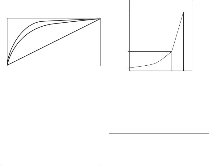
Gamma
Functions
Setting examples
Used for setting gamma compensation to OFF, ON (1), |
3 (003h) : |
14 s (1/100000) |
|||
32 (020h) : 1.005 ms (1/1000) |
|||||
or ON (2). |
|||||
100 (064h) : |
10.005 ms (1/100) |
||||
OFF : Outputs CCD signals for image processing |
|||||
1000 (3E8h) : |
1 s |
|
|||
|
linearly. |
|
|||
|
1010 (3F2h) : |
2 s |
|
||
ON (1) : For obtaining natural gradation taking into |
|
||||
1150 (47Eh) : |
16 s |
|
|||
|
account the characteristics of the monitor. |
|
|||
|
|
|
|
||
ON (2) : For obtaining three-dimensional images with |
|
|
|
||
|
a subject that has a small luminance dynamic |
|
|
|
|
|
range. |
16 s |
|
|
|
|
Gamma ON (2) |
|
|
|
|
|
|
|
2 |
|
|
Output |
Gamma ON (1) |
|
|
|
|
Gamma OFF |
|
|
|
||
|
1 s |
|
|
||
|
|
|
|
||
|
|
1 |
|
|
|
|
Input |
10 s |
|
|
|
|
Concept of Gamma Characteristics |
3 |
1000 |
1150 |
|
Shutter
This feature sets exposure time. Both manual and automatic settings are available.
When the automatic setting is selected, Shutter is adjusted automatically, based on the brightness of the subject.
At this time, the reference level (target point) of the brightness is set in the Auto Exposure register.
With manual setting, the camera uses relative control values indicated by a 12-bit integer and absolute control values indicated using a 32-bit floating point number.
Relative control values for Shutter
The relationship between the parameter and the exposure time is given by the following formulas. Where
P = Parameter (003h ~ 47Eh) |
|
|
|
|||
E = Exposure time (s) |
|
|
|
|||
P >= 3 |
~ P <= 1000 |
|
|
|
||
|
P2 |
|
|
|
||
E = |
|
+ 0.000005 |
|
|
1 |
|
1000000 |
|
|
||||
|
|
|
|
|
|
|
P > 1000 ~ P <= 1150 |
|
|
|
|||
E = (P – 1000)*0.1 + 1.000005 |
|
2 |
||||
|
||||||
For details on Auto Exposure, see page 8.
For long exposure times
When exposure times longer than the currently set frame rate cycle are set, the camera enters the long exposure time mode, and the actual frame rate is slowed in accordance with the exposure time.
Absolute control values for Shutter
Control of exposure time using absolute values is possible. The values are indicated using a 32-bit floating point value. (Unit: sec.)
The control steps are synchronized with the pixel clock, and as the pixel clock is 15.25 MHz, one step is approximately 65.6 ns.
The range for these values extends from 10 microseconds to 17.5 seconds.
Programming example;
union {
DWORD |
dwValue; |
// 1394 is expressed in quadlets, |
float |
fValue; |
// exposure time is indicated in seconds. |
} AbsoluteShutterValue;
AbsoluteShutterValue.fValue = Exposure time;
WriteQuad(AbsoluteShutterOffsetAddress,
AbsoluteShutterValue.dwValue);
WriteQuad is a virtual function used to write in the 1394 register.
DFW-SX910/X710 |
9 |
AbsoluteShutterOffsetAddress is an offset address for the absolute value control. See page 26 for the formula for the offset address.
The change in shutter time will be used when the next exposure starts. The current exposure will complete with the previous shutter setting. This is true for all exposure; short or long. If you intend to reflect the new setting immediately, stop the output and start it again.
Gain
This feature adjusts the brightness of the picture. Both manual and automatic settings are available. The variable range extends from 0 to 18 dB.
When automatic setting is selected, Gain is adjusted automatically, based on the brightness of the subject. At this time, the reference level (target point) of the brightness is set in the Auto Exposure register.
For details on Auto Exposure, see page 8.
Functions
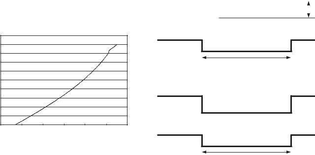
Trigger Shutter
This feature allows you to control the exposure timing via a external signal input (Hardware Trigger) or via a command sent from application software (Software Trigger). There are two trigger modes:
–Trigger Mode 0 where the exposure time is controlled by the shutter parameter
–Trigger Mode 1 where the exposure time is
controlled by the trigger pulse width.
In both modes, the leading edge of the hardware trigger starts the exposure. In Trigger Mode 0, the maximum exposure is limited by the shutter parameter. In Trigger Mode 1, there is no limit to the exposure time.
Software Trigger is defined by IIDC Standard, v1.31.
Trigger Mode 0
70 to 511 |
Gain = 20log10([658+code]/[658–code])– 0.35 |
|||||
512 to 551 |
Gain =(0.0354)(code)– 0.35 |
|
|
|||
20.00 |
|
|
|
|
|
|
18.00 |
|
|
|
|
|
|
16.00 |
|
|
|
|
|
|
14.00 |
|
|
|
|
|
|
12.00 |
|
|
|
|
|
|
10.00 |
|
|
|
|
|
|
8.00 |
|
|
|
|
|
|
6.00 |
|
|
|
|
|
|
4.00 |
|
|
|
|
|
|
2.00 |
|
|
|
|
|
|
0.00 |
|
|
|
|
|
|
0 |
100 |
200 |
300 |
400 |
500 |
600 |
|
|
|
|
|
Input signal |
|
4.0 to 5.0 Vp-p |
|
|
|
|
|||
|
|
|
|
|
|
|
|
|
|

 Trigger width: 10 s or wider
Exposure time
Set the exposure time using the Shutter feature.
Trigger Mode 1
Input signal
Exposure time
Set the exposure time using the width of the trigger signal pulse.
• Input impedance: 10 kΩ
It is possible to trigger the cameras at full frame rate using hardware trigger. (This was not possible with the earlier DFW-SX900/X700 because the trigger in would not be accepted until after the previous images was output from the camera.) It is very important that the exposure not end before the previous image is out of the cameras. If the camera is trigger too fast or there is noise on the trigger line that will cause the exposure to end before previous image is output, you will get double exposure of the image.
DFW-SX910/X710 |
10 |
Pan/Tilt
Pan/Tilt is a feature to move a region of interest (ROI) image (smaller than the full image) vertically and horizontally about the full image of the camera. When the ROI image is defined (use the video mode setup), the ROI is centered in the full image.
Optical Filter
Normally, Optical Filter is the feature which switches electronic optical filters, such as an ND filter or a color conversion filter. However, on this camera, the feature chooses the preset values of White Balance. If 0 is set, White Balance for 3200 K is utilized. If 1 is set, White Balance for 5600 K is utilized.
This feature is effective when the color temperature of the shooting environment is 3200 K or 5600 K.
Memory Channels
The camera is equipped with two channels of nonvolatile memory to hold camera settings. The settings of all camera features and the video mode can be stored. The camera memorizes the channel most recently used to read out the setting information, and retains it, even if the power is turned off. Therefore, the camera loads the information from that channel when the power is turned on.
The video mode settings are loaded only when the power is turned on.
To start up the camera with the desired setting, perform the following procedure.
1Make changes to the camera features or the video mode settings.
2Store the current setting in Memory Channel 1 or Memory Channel 2.
3Load the information that was stored in step 2.
When you start up the camera the next time, the settings that you have just made will be loaded automatically.
Functions
Using the CameraInitialize command, the setting information stored in the channels is cleared and the camera features and the video mode are reset to their initial values. To preserve the information in the channels, be sure not to send the CameraInitialize command while driver software or application software is starting up.
The value saved for Pan/Tilt is initialized when the video mode is changed. To preserve the value, be sure not to change the video mode while driver software or application software is starting up, or before sending the video start command.
DFW-SX910/X710 |
11 |

Functions
Partial Scan
The Partial Scan feature for outputting a small part of the full image called a Region of Interest (ROI). The ROI can be defined as any single contiguous rectangle that can be drawn on an even 16×16 grid of the whole image. The Unit Cell is the smallest region of interest that can be defined as is one of the rectangles on the even 16×16 grid.
DFW-SX910 unit cell = 80×60 pixels DFW-X710 unit cell = 64×48 pixels
Cutting by Partial Scan mode
Direction)(Vertical
Vertical
Horizontal (Horizontal Direction)
The frame rate of the camera can be increased by reducing the number of vertical lines output. In Partial Scan mode, the frame rate is determined by the exposure/shutter time plus the time to transmit the image. In free run mode, the exposure starts after the last image is transmitted. In triggered mode, the exposure can be overlapped with the image output but care must be taken to ensure that the exposure end does not occur before the ouput of the previous image.
To use the Partial Scan feature, set Format7, Mode0.
In Partial Scan mode, you can select from among
Mono8, YUV4:1:1, and YUV4:2:2 as the color coding.
DFW-SX910/X710 |
12 |
IIDC Extended
Features
Following are vender-unique features, which are not defined by the IIDC standard.
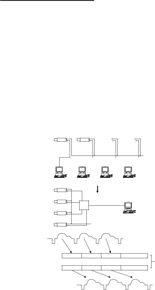
Memory Shot
Memory Shot allows the camera to collect one or more images into on-board image memory without tying up available 1394 bus bandwidth. Normally, a 1394 IIDC camera transmits a new image immediately after the acquisition so the 1394 bus bandwidth is pre-allocated to the camera to ensure deterministic performance. 1394 bus bandwidth is allocated based on resolution and frame rate assigned. Multiple camera configurations frequently demand more bandwidth (or more ISO channels) than available on a single 1394 bus. The user can either reduce the bandwidth required by each cameras by reducing the frame rate or resolution or increase available bandwidth by adding more 1394 busses on one or more computers. Memory Shot offers another alternative to managing the 1394 bus bandwidth in multiple camera configurations. This
Functions
is especially useful in hardware triggered environments. Multiple cameras can be setup to acquire one or more images simultaneously without consuming any 1394 bus bandwidth. The applications software can setup the multiple cameras on a single 1394 bus on one computer for Memory Shot acquisition, query the camera to verify that the image(s) are in the camera on-board memory, and tell each camera to transmit its stored image(s). These cameras have 128 Mbit of frame memory.
It can hold:
1280×960 at YUV4:2:2 is 6 images
1280×960 at YUV4:1:1 is 9 images
1280×960 at MONO8 is 13 images
The number of images (N) that can be holded is defined by the image size and color coding.
N = 16 * 1024 * 1024 (byte) / ( W * H * K ) W: image width (pixels)
H: image hight (pixels)
K: coefficient of color coding
|
|
|
|
|
|
K |
color coding |
|||||||
|
|
|
|
|
|
|
|
|
|
|
|
|
|
|
|
|
|
|
|
|
1 |
|
|
|
|
Mono8/Raw8 |
|||
|
|
|
|
|
|
|
|
|
|
|
|
|
|
|
|
|
|
|
|
|
1.5 |
|
|
YUV4:1:1 |
|||||
|
|
|
|
|
|
|
|
|
|
|
|
|
|
|
|
|
|
|
|
|
2 |
|
|
|
|
YUV4:2:2 |
|||
|
|
|
|
|
|
|
|
|
|
|
|
|
|
|
|
|
|
|
|
|
|
|
|
|
|
|
|
|
|
Trigger input
|
|
|
1394 |
|
|
|
|
1394 |
|
|
|
|
|
1394 |
|
1394 |
||||||||||||||||||||
|
|
|
|
|
|
|
|
|
|
|
|
|
|
|
|
|
|
|
|
|
|
|
|
|
|
|
|
|
|
|
|
|
|
|
|
|
|
|
|
|
|
|
|
|
|
|
|
|
|
|
|
|
|
|
|
|
|
|
|
|
|
|
|
|
|
|
|
|
|
|
|
|
|
|
|
|
|
|
|
|
|
|
|
|
|
|
|
|
|
|
|
|
|
|
|
|
|
|
|
|
|
|
|
|
|
|
|
|
|
|
Conventional system
1394
Power repeater
Trigger input
|
|
|
Images input |
|
|
|
|
from CCD |
|
Acquisition |
image 1 |
image 2 |
image 3 |
|
phase |
||||
|
|
128 Mbit |
||
|
|
|
||
Transmission |
|
|
frame memory |
|
image 1 |
image 2 |
image 3 |
||
phase |
||||
|
|
|
||
|
|
|
You can specify the timing of the |
|
|
|
|
transmission of the stored images. |
|
Images output to |
|
|
||
1394 bus |
|
|
|
|
DFW-SX910/X710 |
13 |
 Loading...