


74HCT283U
Philips 74HCT283U, 74HCT283PW, 74HCT283N, 74HCT283DB, 74HCT283D Datasheet
...
DATA SH EET
Product specification
File under Integrated Circuits, IC06
December 1990
INTEGRATED CIRCUITS
74HC/HCT283
4-bit binary full adder with fast carry
For a complete data sheet, please also download:
•The IC06 74HC/HCT/HCU/HCMOS Logic Family Specifications
•The IC06 74HC/HCT/HCU/HCMOS Logic Package Information
•The IC06 74HC/HCT/HCU/HCMOS Logic Package Outlines

December 1990 2
Philips Semiconductors Product specification
4-bit binary full adder with fast carry 74HC/HCT283
FEATURES
• High-speed 4-bit binary addition
• Cascadable in 4-bit increments
• Fast internal look-ahead carry
• Output capability: standard
• ICC category: MSI
GENERAL DESCRIPTION
The 74HC/HCT283 are high-speed Si-gate CMOS devices
and are pin compatible with low power Schottky TTL
(LSTTL). They are specified in compliance with JEDEC
standard no. 7A.
The 74HC/HCT283 add two 4-bit binary words (A
n
plus Bn)
plus the incoming carry. The binary sum appears on the
sum outputs (∑1 to ∑4) and the out-going carry (C
OUT
)
according to the equation:
CIN+ (A1+ B1) +2(A2+ B2) ++4(A3+ B3) + 8(A4+ B4)=
=∑1+2∑2+4∑3+8∑4+16C
OUT
Where (+) = plus.
Due to the symmetry of the binary add function, the “283”
can be used with either all active HIGH operands (positive
logic) or all active LOW operands (negative logic); see
function table. In case of all active LOW operands the
results ∑1 to ∑4 and C
OUT
should be interpreted also as
active LOW. With active HIGH inputs, CIN must be held
LOW when no “carry in” is intended. Interchanging inputs
of equal weight does not affect the operation, thus CIN, A1,
B1 can be assigned arbitrarily to pins 5, 6, 7, etc.
See the “583” for the BCD version.
QUICK REFERENCE DATA
GND = 0 V; T
amb
=25°C; tr=tf= 6 ns
Notes
1. C
PD
is used to determine the dynamic power dissipation (PD in µW):
PD=CPD× V
CC
2
× fi+∑(CL× V
CC
2
× fo) where:
fi= input frequency in MHz
fo= output frequency in MHz
∑ (CL× V
CC
2
× fo) = sum of outputs
CL= output load capacitance in pF
VCC= supply voltage in V
2. For HC the condition is VI= GND to V
CC
For HCT the condition is VI= GND to VCC− 1.5 V
SYMBOL PARAMETER CONDITIONS
TYPICAL
UNIT
HC HCT
t
PHL
/ t
PLH
propagation delay CL= 15 pF; VCC=5 V
C
IN
to ∑
1
16 15 ns
C
IN
to ∑
2
18 21 ns
C
IN
to ∑
3
20 23 ns
C
IN
to ∑
4
23 27 ns
A
n
or Bn to ∑
n
21 25 ns
C
IN
to C
OUT
20 23 ns
A
n
or Bn to C
OUT
20 24 ns
C
I
input capacitance 3.5 3.5 pF
C
PD
power dissipation capacitance per package notes 1 and 2 88 92 pF
December 1990 3
Philips Semiconductors Product specification
4-bit binary full adder with fast carry 74HC/HCT283
ORDERING INFORMATION
See
“74HC/HCT/HCU/HCMOS Logic Package Information”
.
PIN DESCRIPTION
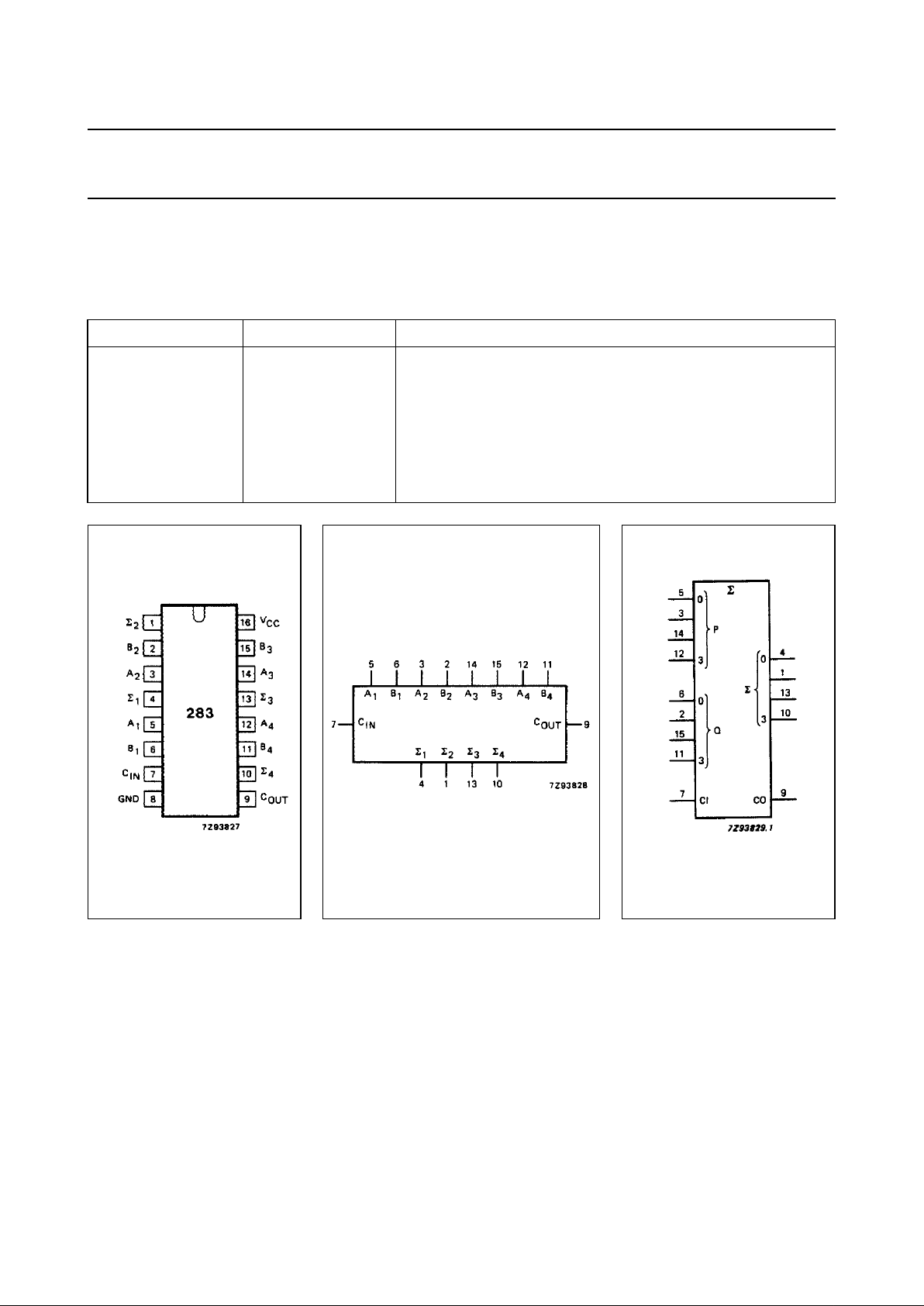
PIN NO. SYMBOL NAME AND FUNCTION
4, 1, 13, 10 ∑
1
to ∑
4
sum outputs
5, 3, 14, 12 A
1
to A
4
A operand inputs
6, 2, 15, 11 B
1
to B
4
B operand inputs
7C
IN
carry input
8 GND ground (0 V)
9C
OUT
carry output
16 V
CC
positive supply voltage
Fig.1 Pin configuration. Fig.2 Logic symbol. Fig.3 IEC logic symbol.
 Loading...