


 Loading...
Televisions
7000 series
65PFL7900
55PFL7900
49PFL7900
Register your product and get support at
www.philips.com/welcome
EN User Manual
ES Manual del Usuario
FR Manuel d’Utilisation
EN For further assistance, call the customer support service in your country.
•To obtain assistance, contact Philips Customer Care Center; In the U.S.A., Canada, Puerto Rico, or the U.S. Virgin Islands
1 866 202 5960
México D.F. and Área Metropolitana; 58 87 97 36 Interior de la Republica; 01 800 839 19 89
ES Para obtener más información, llame al servicio de soporte al cliente de su país.
•Para obtener asistencia, comuníquese con Centro de atención al cliente de Philips;
En los Estados Unidos, en Canadá, Puerto Rico o en las Islas Vírgenes de los Estados Unidos; 1 866 202 5960
México D.F. y Área Metropolitana; 58 87 97 36 Interior de la Republica; 01 800 839 19 89
FR Pour obtenir de l’aide supplémentaire, communiquez avec le centre de service à la clientèle de votre pays.
•Pour obtenir de l’aide, communiquez avec le centre de service à la clientèle Philips au;
Dans le États-Unis, au Canada, à Puerto Rico ou aux Îles Vierges américaines; 1 866 202 5960
México D.F. et Área Metropolitana; 58 87 97 36 Interior de la Republica; 01 800 839 19 89

Contents
1 |
Notice |
5 |
|
|
|
2 |
Important |
7 |
|
Positioning the TV |
7 |
|
Regulatory notices |
7 |
|
Environmental care |
7 |
|
Preparing to move / ship the unit |
7 |
|
|
|
3 |
Getting started |
8 |
|
Features |
8 |
|
Supplied accessories |
8 |
|
Symbols used in this User manual |
8 |
|
Unpacking |
9 |
|
Installing the stands |
10 |
|
Lifting the TV set |
10 |
|
Removing cardboard |
10 |
|
Installing the remote control batteries |
11 |
|
Remote control |
12 |
|
Control panel |
13 |
|
Terminals |
13 |
|
Connecting Antenna or Cable / Satellite / IPTV set-top box |
14 |
|
Plugging in the AC power cord |
14 |
|
Selecting your connection quality |
15 |
|
Connecting your devices |
15 |
|
Initial setup |
19 |
|
|
|
4 |
Use your TV |
21 |
|
Switching on your TV and putting it in standby mode |
21 |
|
Adjusting volume |
21 |
|
Switching channels |
21 |
|
Watching channels from an external device |
22 |
|
Access the Home menu |
22 |
|
Create a list of favorite channels |
23 |
|
Changing Picture format |
23 |
|
TV screen information |
24 |
|
Using options menu |
25 |
|
USB |
26 |
|
|
|
5 Getting more from your TV |
29 |
|
|
Picture and sound setup |
30 |
|
TV settings |
30 |
|
Picture |
30 |
|
Sound |
32 |
|
Features |
33 |
|
Installation |
34 |
2 .English
|
Search for channels |
37 |
|
Install channels |
37 |
|
Channel settings |
37 |
|
Channel installation |
37 |
|
Child lock |
38 |
|
Change PIN |
39 |
|
Digital audio language |
39 |
|
Mono/Stereo |
39 |
|
Connect to network |
40 |
|
Wireless setting |
40 |
|
Wired setting |
40 |
|
Network settings |
41 |
|
Manual network settings |
41 |
|
Connection test |
43 |
|
Setting status |
43 |
|
Home network |
44 |
|
Wake-on-LAN(DIAL) |
44 |
|
Net TV |
44 |
|
Reset network settings |
44 |
|
Update software |
45 |
|
Preparing for the software upgrade |
45 |
|
Downloading the software |
45 |
|
USB upgrade |
45 |
|
Network updates |
46 |
|
Software settings |
46 |
|
Software |
46 |
|
Miracast |
47 |
|
View photos, play music and watch videos using home |
|
|
network |
47 |
|
Net TV |
50 |
|
Pandora operations |
51 |
|
|
|
6 |
Useful tips |
52 |
|
FAQ |
52 |
|
Troubleshooting tips |
53 |
|
|
|
7 |
Information |
55 |
|
Glossary |
55 |
|
Maintenance |
55 |
|
|
|
8 |
Specifications |
56 |
|
|
|
9 |
Warranty |
57 |
|
License |
end of book |
• Displays and illustrations may differ depending on the product you purchase.

3 .English
Register online today at www.philips.com/welcome today to get the most benefits from your purchase.
Registering your model with Philips makes you eligible for all of the valuable benefits listed below, so don't miss out.
Register Online at www.philips.com/welcome to ensure:
*Product safety notification
By registering your product, you'll receive notification - directly from the manufacturer - in the rare case of a product recall or safety defect.
*Additional benefits
Registering your product guarantees that you'll receive all of the privileges to which you're entitled, including special money-saving offers.
Know these safety symbols
CAUTION
RISK OFELECTRIC SHOCK
DO NOTOPEN
CAUTION: TO REDUCE THE RISK OF ELECTRIC SHOCK, DO NOT REMOVE COVER (OR BACK). NO USER-SERVICEABLE PARTS ARE INSIDE. REFER SERVICING TO QUALIFIED SERVICE PERSONNEL.
The caution marking is located on the rear or bottom of the cabinet.
The lightning flash with arrowhead symbol, within an equilateral triangle, is intended to alert the user to the presence of uninsulated “dangerous voltage” within the apparatus’s enclosure that may be of sufficient magnitude to constitute a risk of electric shock to persons.
The exclamation point within an equilateral triangle is intended to alert the user to the presence of important operating and maintenance (servicing) instructions in the literature accompanying the apparatus.
WARNING: To reduce the risk of fire or electric shock, do not expose this apparatus to rain or moisture. Apparatus shall not be exposed to dripping or splashing and no objects filled with liquids, such as vases, shall be placed on the apparatus.
CAUTION: To prevent electric shock, match wide blade of plug to wide slot, fully insert.
ATTENTION: Pour éviter les choc électriques,introduire la lame la plus large de la fiche dans la borne correspondante de la prise et pousser jusqu’au fond.
For fastest support visit us online for chat and self service solutions at www.philips.com/support

4 .English
Important safety instructions
1.Read these instructions.
2.Keep these instructions.
3.Heed all warnings.
4.Follow all instructions.
5.Do not use this apparatus near water.
6.Clean only with dry cloth.
7.Do not block any ventilation openings. Install in accordance with the manufacturer’s instructions.
8.Do not install near any heat sources such as radiators, heat registers, stoves, or other apparatus (including amplifiers) that produce heat.
9.Do not defeat the safety purpose of the polarized or grounding type plug. A polarized plug has two blades with one wider than the other. A grounding type plug has two blades and a third grounding prong. The wide blade or the third prong are provided for your safety. If the provided plug does not fit into your outlet, consult an electrician for replacement of the obsolete outlet.
10.Protect the power cord from being walked on or pinched particularly at plugs, convenience receptacles, and the point where they exit from the apparatus.
1 1. Only use attachments / accessories specified by the manufacturer.
12. Use only with the cart, stand, tripod, bracket, or table specified by the manufacturer, or sold with the apparatus. When a cart is used, use caution when moving the cart / apparatus combination to avoid injury from tip-over.
13.Unplug this apparatus during lightning storms or when unused for long periods of time.
14.Refer all servicing to qualified service personnel. Servicing is required when the apparatus has been damaged in any way, such as power-supply cord or plug is damaged, liquid has been spilled or objects have fallen into the apparatus, the apparatus has been exposed to rain or moisture, does not operate normally, or has been dropped.
Note to the CATV system installer:
This reminder is provided to call the CATV system installer’s attention to Article 820-40 of the NEC that provides guidelines for proper grounding and, in particular, specifies that the cable ground shall be connected to the grounding system of the building, as close to the point of cable entry as practical.
Example of antenna grounding as per NEC - National Electric Code
GROUND CLAMP |
ANTENNA LEAD IN WIRE |
|
|
||
|
ANTENNA DISCHARGE UNIT |
|
|
(NEC SECTION 810-20) |
|
|
GROUNDING CONDUCTORS |
|
|
(NEC SECTION 810-21) |
|
|
GROUND CLAMPS |
|
ELECTRIC SERVICE EQUIPMENT |
POWER SERVICE GROUNDING |
|
ELECTRODE SYSTEM (NEC ART 250, |
||
|
||
|
PART H) |
Wall mount bracket kit
Brand |
Model # |
Screw dimension |
49PFL7900
SANUS VMPL3 M6 x 0.472” (12mm)
55PFL7900
 Do NOT use screws packed with Wall Mount Bracket Kit.
For 65 inch TVs, you need to purchase screws separately with dimensions described below.
65PFL7900 SANUS VMPL3
M6 x 1.181” (30mm)
with spacer
•Your TV meets the VESA standard for wall mounting. Consult with your local dealer for a wall mount bracket which is compatible with your TV model.
•The recommended wall mount bracket kit (sold separately) allows the mounting of the TV on the wall.
•For detailed information on installing the wall mount, refer to the wall mount Instruction book.
•P&F USA is not responsible for any damage to the product or injury to yourself or others if you elect to install the TV wall mount bracket or mount the TV onto the bracket on your own.
•The wall mount bracket must be installed by experts.
P&F USA is not liable for these types of accidents or injuries noted below.
•Install the wall mount bracket on a sturdy vertical wall.
•If installed onto a ceiling or slanted wall, the TV and wall mount bracket may fall which could result in a severe injury.
•Do not use screws that are longer or shorter than their specified length. If screws too long are used this may cause mechanical or electrical damage inside the TV set. If screws too short are used this may cause the TV set to fall.
•Do not fasten the screws by excessive force. This may damage the product or cause the product to fall, leading to an injury.
•For safety reasons use 2 people to mount the TV onto a wall mounting bracket.
•Do not mount the TV onto the wall mounting bracket while your TV is plugged in or turned on. It may result in an electrical shock injury.
When installing the unit on the wall, allow this much space.
Top |
: 1 1.8 inches (30cm) |
|
Left and right side |
: |
5.9 inches (15cm) |
Bottom |
: |
3.9 inches (10cm) |
5 .English
1 Notice
Declaration of conformity
Trade name |
: |
PHILIPS |
Responsible party |
: |
P&F USA, Inc. |
Model |
: 65PFL7900, 55PFL7900, 49PFL7900 |
|
Address |
: PO Box 2248, Alpharetta, GA 30023-2248 U.S.A. |
|
Telephone number |
: |
1 866 202 5960 |
The following FCC/IC RSS applies to the Wireless LAN adapter included in this product.
FCC Caution: Any changes or modifications not expressly approved by the party responsible for compliance could void the user’s authority to operate this equipment.
This transmitter must not be co-located or operating in conjunction with any other antenna or transmitter.
Country Code Statement
For product available in the USA market, only channel 1 1 1 can be operated. Selection of other channels is not possible.
To maintain compliance with FCC RF exposure requirements, use only belt-clips, holsters or similar accessories that do not contain metallic components in its assembly. The use of accessories that do not satisfy these requirements may not comply with FCC RF exposure requirements and should be avoided.
This device complies with Industry Canada license-exempt RSS standard(s). Operation is subject to the following two conditions: (1) this device may not cause interference and (2) this device must accept any interference, including interference that may cause undesired operation of the device.
5150-5250 MHz band is restricted to indoor operations only.
High-power radars are allocated as primary users (i.e. priority users) of the bands 5250-5350 MHz and 5650-5850 MHz and that these radars could cause interference and/or damage to LE-LAN devices.
Compliance with IC requirement RSS-210 A9.4.4
Data transmission is always initiated by software, which is the passed down through the MAC, through the digital and analog baseband, and finally to the RF chip. Several special packets are initiated by the MAC. These are the only ways the digital baseband portion will turn on the RF transmitter, which it then turns off at the end of the packet. Therefore, the transmitter will be on only while one of the aforementioned packets is being transmitted. In other words, this device automatically discontinue transmission in case of either absence of information to transmit or operational failure.
6 .English
CinemaNow and the CinemaNow logo are trademarks of BestBuy Stores L.P. and BestBuy Canada LTD.
Some features may require an always-on broadband internet connection, firmware update and/or a minimum bandwidth. Internet services vary by location.
P&F USA Inc. / P&F MEXICANA, S.A.de C.V. do not warrant access to the portal or to any of the services, content, software and advertising. P&F USA Inc./P&F MEXICANA, S.A. de C.V. or third party content/ service providers may, in their sole discretion, add or remove access to any specific services, content, software and advertising at any time. Although P&F USA Inc. / P&F MEXICANA, S.A. de C.V. will strive to provide a good selection of services, content or software, P&F USA Inc./ P&F MEXICANA, S.A. de C.V. do not warrant continued access to any specific services, and content or software.
P&F USA Inc. / P&F MEXICANA S.A. de C.V. do not warrant Miracast compatibility with all source devices such as smartphones, tablets, laptops, etc. due to large variability in hardware, firmware, drivers, software and implementation of wireless casting applications on these source devices. Although P&F USA Inc. / P&F MEXICANA S.A. de C.V. will strive to enhance compatibility and performance across a range of source devices, P&F USA Inc. / P&F MEXICANA S.A. de C.V. do not warrant compatibility with specific source devices.

2 Important
7 .English
Environmental care
Positioning the TV
End of life directives
Preparing to move / ship the unit
Regulatory notices
AC power plug

2 Getting started
Features
• DTV / Analog TV / CATV
You can use your remote control to select channels which are broadcast in digital format and conventional analog format. Also, cable and satellite subscribers can access their TV channels.
• Information display
YoucandisplayontheTVscreenthetitle,contents(DTVonly)andotherinformationonthecurrent program.
• Autoprogram
This unit automatically scans and memorizes channels available in your area, eliminating difficult setup procedures.
• Net TV
This unit lets you enjoy internet services. Use the remote control to browse the Net TV pages. You can play movies and much more, all from your TV screen.
• Child lock
This feature allows you to block children’s access to inappropriate programs.
• Closed caption decoder
Built-in closed caption decoder displays text for closed caption supported programs.
• MTS / SAP tuner
Audio can be selected from the remote control.
• Auto standby
If there is no input signal and no operation for 15 minutes, the unit will go into standby mode automatically.
• Sleep timer
You can set the unit to go into standby mode after a specific amount of time.
• Choices for on-screen language
Select your on-screen language: English, Spanish or French.
•Stereo sound function
•PLL frequency synthesized tuning
Provides free and easy channel selection and lets you tune directly to any channel using the number and decimal point “•” keys on the remote control.
• Various adjustments for picture and sound
Customizes picture quality suitable for your room and sets your sound preference.
• EasyLink via HDMI link
EasyLink allows your other HDMI link devices to be controlled by the HDMI cable connected to your TV.
•HDMI input
•HDMI-DVI input
If your video device has a DVI output jack, use an HDMI-DVI conversion cable to connect the unit.
•Component video input
•PC input
•AV input
Audio and video input from an external device.
• USB terminal
The picture, music and video files stored on a USB memory stick can be played back on this unit.
•Digital audio output
•Headphone audio output
Headphone 3.5mm stereo jack for personal listening.
8 .English
Supplied accessories
User Manual |
Quick Start guide |
Caution Sheet |
|||||||||||||
|
|
|
|
|
|
|
|
|
|
|
|
|
|
|
|
|
|
|
|
|
|
|
|
|
|
|
|
|
|
|
|
|
|
|
|
|
|
|
|
|
|
|
|
|
|
|
|
|
|
|
|
|
|
|
|
|
|
|
|
|
|
|
|
|
|
|
|
|
|
|
|
|
|
|
|
|
|
|
|
|
|
|
|
|
|
|
|
|
|
|
|
|
|
|
|
|
|
|
|
|
|
|
|
|
|
|
|
|
|
|
|
|
|
|
|
|
|
|
|
|
|
|
|
|
|
|
|
|
|
|
|
|
|
|
|
|
|
|
|
|
|
|
|
TV base and Screws |
Remote Control |
|
and Batteries |
|
(AAA, 1.5V x 2) |
|
|
AAA AAA |
|
Screws packed with this Unit. |
|
|
|
|
|
|
|
Model |
Quantity |
Size |
|
|
|
|
|
65PFL7900 |
6 |
M4 x 0.551”(14mm) |
|
|
|
|
|
55PFL7900 / |
6 |
M4 x 0.472”(12mm) |
|
49PFL7900 |
|
||
|
|
|
|
|
|
|
|
 Note(s)
•Ifyoulosethescrews,pleasepurchasetheabove-mentionedPhillipsheadscrewsatyourlocal store.
•Ifyouneedtoreplacetheseaccessories,pleaserefertothepartnameorNo.withtheillustrations and call our toll free customer support line found on the cover of this User manual.
When using a universal remote control to operate this unit.
•Make sure the component code on your universal remote control is set to our brand. Refer to the instruction book accompanying your remote control for more details.
•We do not guarantee 100% interoperability with all universal remote controls.
Symbols used in this User manual
The following is the description for the symbols used in this User manual. Description refers to:
Digital TV operation
Cable / NTSC (Analog) TV operation
• If neither symbol appears, the operation is applicable to both.
Continued on next page.
9 .English
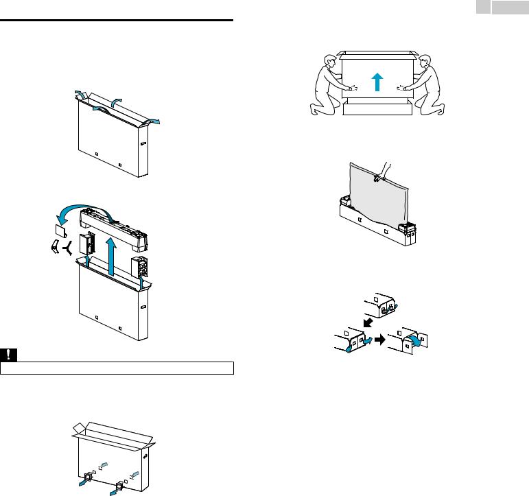
Unpacking
It is recommended that two or more people remove the TV set from the box. Thin TVs can easily bend. To avoid damage to this TV and its screen, it MUST NOT be carried in a horizontal position when being moved.
1Open the top flaps of the box.
4Remove the outer slipbox with care.
5 Support the top of the TV set with a hand to prevent the TV from falling.
2Remove all accessories.
6 Unhinge the retaining tabs and unfold the left and right side of the bottom packaging.
Caution(s)
•DO NOT take the TV set out of the box yet.
3Remove the packing joints* from the box.
*65PFL7900 (x6) 49PFL7900, 55PFL7900 (x4)
Continued on next page.
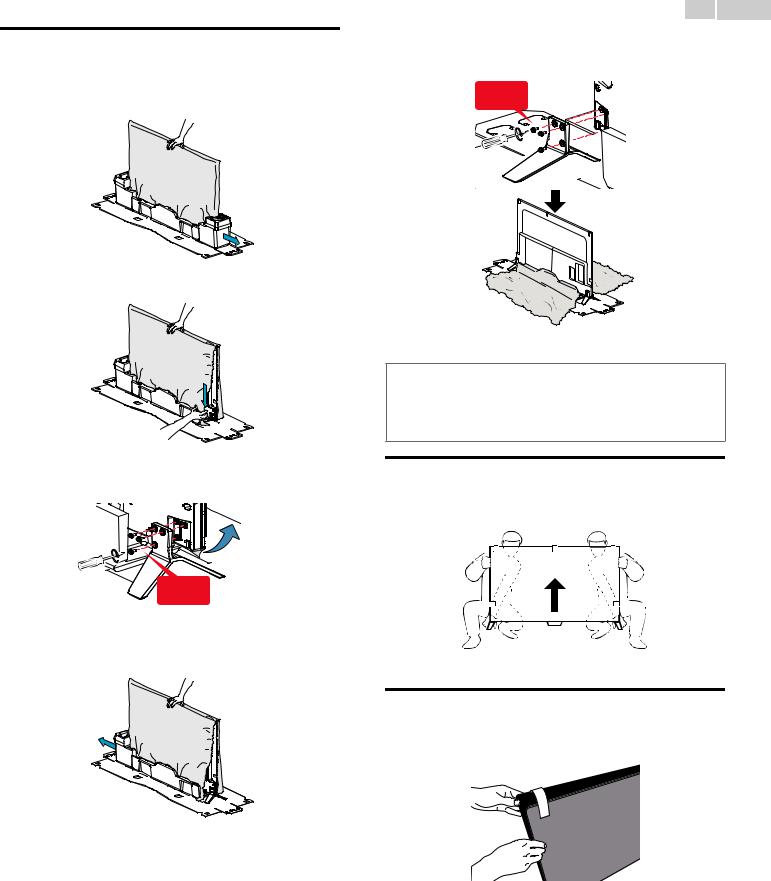
Installing the stands
You must support the top of the TV set at all times to prevent the TV from falling.
1Remove one of the bottom polystyrene foam bases.
2Rip the plastic bag until the bottom corner of the TV is exposed.
3Remove the protective film on the bottom of the TV and fasten the matching stand to the TV with 3 screws (included).
3 screws required
4Remove the other bottom polystyrene foam base and rip the plastic bag on this side as shown in step 2.
10 .English
5Fasten the other stand to the TV with 3 screws.
• Both stands should now be securely fastened.
3 screws required
 Note(s)
•A wide open space is recommended for assembly.
•A Phillips-head screwdriver is required to fasten the stands to the TV set.
•When attaching the stand, ensure that all screws are tightly fastened. If the stand is not properly attached, it could cause the unit to fall, resulting in injuries as well as damage to the unit.
•To remove the stand from this unit, unscrew the Phillips-head screws by reversing the procedure. Be careful not to drop the stand when you remove it.
Lifting the TV set
Carefully lift the TV set as shown in the illustration and place it onto a stable, level surface.
Removing cardboard
Remove the cardboard attached to the screen. You are now ready to set up and enjoy your Philips TV.
Continued on next page.
11 .English
Installing the remote control batteries
1
2
3
Slide the battery cover off the back of the remote control.
Insert the two supplied batteries (AAA, 1.5V). Be sure the + and – ends of the batteries line up with the markings inside the case.
Slide the cover back into position.
Note(s)
•Remove the batteries if not using the remote control for an extended period of time.
Continued on next page.
12 .English
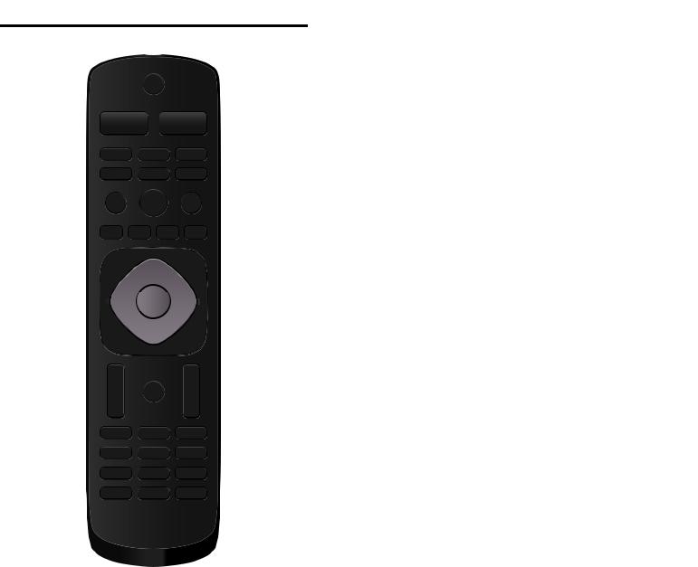
Remote control
(POWER)
Turns the TV on from standby or off to standby.
VUDU
Access directly to VUDU.
|
a |
EasyLink buttons |
||
|
|
|
/ : Searches backward or forward through the disc. |
|
|
|
|
. |
: Starts, pauses or resumes playback. |
s |
b |
|
. |
: Stops the disc playback. |
r |
c |
|
Note(s) |
|
|
•Pause may not work properly on some devices even if they are EasyLink (HDMI CEC) |
|||
|
|
|||
|
|
compliant. |
|
|
q |
d |
SOURCE |
||
|
e |
|
Selects connected devices. |
|
|
(Home) |
|
||
|
f |
|
||
|
|
Displays the main menu. |
||
|
|
|
Apps (APP1 / APP2 / APP3 / APP4) buttons |
|
p |
g |
|
Works as direct access to user specified net apps. |
|
! INFO |
|
|||
|
|
|
||
|
|
|
Displays information about the current program. |
|
|
h |
" OK |
|
|
|
i |
|
Press to decide the command of setting when the Home menu is |
|
|
|
displayed. |
|
|
o |
j |
# (NAVIGATION buttons) |
||
|
Moves the cursor, selects the on-screen menu items. |
|||
|
|
|
||
|
|
$ |
OPTIONS |
|
|
|
|
Displays a list of menu items applicable to the highlighted object or |
|
n |
k |
|
screen. |
|
% CH + / – |
|
|||
|
|
|
||
|
|
|
Selects a channel. |
|
m |
|
& 0 - 9 (NUMBER buttons) |
||
|
|
Used to enter a channel / program number. |
||
|
l |
|
• (DOT) |
: Use with 0-9 to select digital channels. |
|
|
|
|
For example, to enter 2.1, press |
|
|
|
PREV.CH |
: Returns to the previously viewed channel. |
'(MUTE)
Turns the sound on and off.
(VOL + / –
Adjusts the volume.
)BACK
Returns to the previous menu operation.
*FORMAT
Adjusts the picture size on the TV screen.
+NET TV
Access to Net TV menu directly.
,YouTube
Access directly to YouTube.
-NETFLIX
Access directly to Netflix.
Continued on next page.
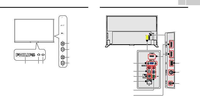
Control panel
 d
d
 e
e
 f
f

 g
g

 h
h
a bc
Power on / Standby indicator
(On : lights in white, Standby : no light)
Remote control sensor
Receives IR signal from remote control.
Ambient light sensor
Alters the brightness of the TV screen automatically by detecting your roomlightinglevel.Donotblockthislightsensorwindowwhichallows proper operation.
(POWER)
Turns the TV on or switches the TV into standby mode.
SOURCE
Selects connected devices.
MENU
Opens the main on-screen menu.
! CH (+) / (–)
Selects a channel. In the menu screen, moves the cursor up ( ) (–) / down ( ) (+).
"VOL (–) / (+)
Adjusts the volume. In the menu screen, moves the cursor left ( ) (–) / right ( ) (+).
VOL (–) : Volume down VOL (+) : Volume up
13 .English
Terminals
i |
o |
j |
p |
|
|
k |
|
l |
q |
|
|
m |
|
n |
|
#PC input jack
VGA cable connection for PC.
$Analog audio (L/R) input jacks
Connect analog audio signals from;
–HDMI-DVI / Analog audio (L/R) jacks signal
–Component video / Analog audio (L/R) jacks signal
–Composite video / Analog audio (L/R) jacks signal
–PC connection / Analog audio (L/R) jacks signal with stereo mini 3. 5mm plug audio cable on PC
%Digital audio output jack
Digital audio (S/PDIF) output to home theaters and other digital audio systems.
&Ethernet port
For internet connection using an Ethernet cable with an RJ-45 connector.
'Component (Y/Pb/Pr) / Composite video (VIDEO) input jack(s) for VIDEO
Composite video input (VIDEO) jack is a shared jack with component video input (Y) jack.
(HDMI input jack(s)
Digital audio and video input from high definition digital devices such as DVD / Blu-ray disc players, cable / satellite set-top boxes, PC’s, etc.
*For HDMI 1 only
In addition to normal HDMI and HDMI-DVI functionality, it outputs TV audio to an HDMI-ARC-compliant device, such as a home theater system.
)USB terminal
Data input from USB memory stick only.
Do not connect any device to this terminal such as digital camera, keyboard, mouse, etc.
*75 ohm cable / Antenna connection
Signal input from an antenna or cable / satellite set-top boxes.
+Headphone audio output jack
Headphone 3.5mm stereo jack for personal listening.
Continued on next page.

Connecting Antenna or Cable / Satellite / IPTV set-top box
Be sure your antenna or another device is connected properly before plugging in the AC power cord.
If connecting to an antenna through an RF cable
Any DTV programs that are broadcast in your area can be received for free through an antenna connection.
|
|
Cable |
IN |
Antenna |
OUT |
|
RF cable |
|
|
|
If connecting Cable / Satellite / IPTV set-top box using an RF cable
If the TV is connected to a cable or set-top box via a coaxial connection, set the TV to channel 3/4 or the channel specified by the service provider.
|
|
RF cable |
IN |
Antenna |
IN |
|
|
OUT |
|
RF cable |
Set-top Box |
|
|
IfconnectingCable/Satellite/IPTVset-topboxusinganHDMI cable
If the TV is connected to a cable / satellite set-top box via an HDMI cable, make sure you select the correct source by using SOURCE.
IN
|
RF cable |
OUT |
IN |
HDMI cable
Set-top Box
If connecting Cable / Satellite / IPTV set-top box using component video input
If the TV is connected to a cable / satellite set-top box via component video input, make sure you select the correct component video source by using SOURCE.
Audio (L/R) cables |
RF cable |
|
|
||
IN |
OUT |
|
IN |
||
IN Component (Y/Pb/Pr) |
Set-top Box |
|
OUT |
||
Video cables |
14 .English
Connecting a Cable / Satellite / IPTV set-top box, Bluray disc / DVD recorder via composite connectors and analog audio
Donotplaceyourrecordertooclosetothescreenbecausesomerecorders can be susceptible to harmful interference from the TV.
|
|
Satellite |
|
|
|
Cable |
|
OUT |
|
Cable |
|
|
|
||
|
|
IN |
|
RF cable |
IN |
Set-top Box |
|
RF cable |
OUT |
OUT |
|
|
|
||
IN |
|
Video + |
|
Audio(L/R) |
|||
|
|||
IN |
|
cables |
|
|
OUT |
IN |
|
|
|
||
Video + Audio(L/R) cables |
|
||
|
Blu-ray Disc / DVD Recorder |
||
 Note(s)
•If you have any question about the DTV’s antenna, visit www.antennaweb.org for further information.
•Depending on your antenna system, you may need different types of combiners (mixers) or separators(splitters)forHDTVsignal.TheminimumRFbandpassonthesedevicesis2,000MHz or 2GHz.
•For your safety and to avoid damage to this unit, please unplug the RF coaxial cable from the antenna input jack before moving the unit.
•If you did use an antenna to receive analog TV, it should also work for DTV reception. Outdoor or attic antennas will be more effective than a set-top box or inside antenna.
•To turn on your reception source easily between antenna and cable, install an antenna selector.
•If you are not receiving a signal from your cable service, contact the cable provider.
Plugging in the AC power cord
Make sure that the AC power cord must be plugged to an AC outlet after all the necessary connections are made.
 Caution(s)
•Connect the analog audio signal cables from the external device to the analog audio L/R input jacks.
•If you have an amplifier, connect the HDMI cable to the HDMI input via your amplifier.
 Note(s)
•Each time you plug in the AC power cord, no operations will be performed for several seconds. This is not a malfunction.
Continued on next page.
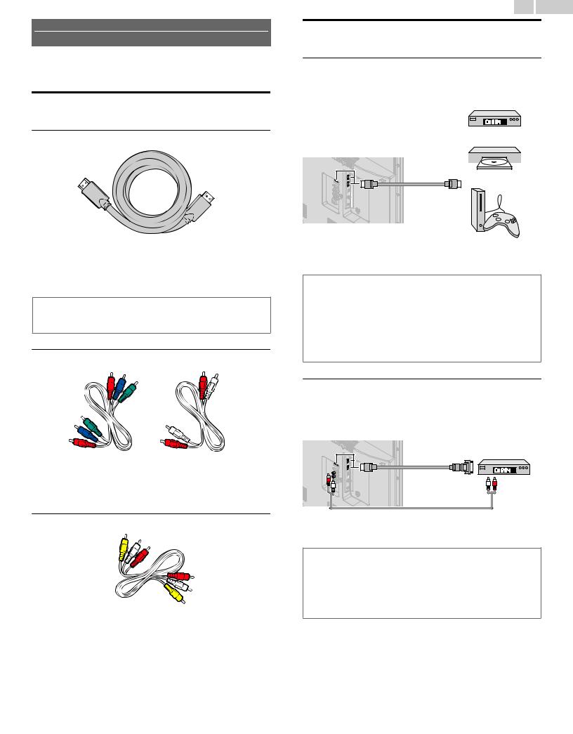
No supplied cables are used with these connections:
•Please purchase the necessary cables at your local store.
Before you connect the AC power cord:
Be sure other devices are connected properly before plugging in the AC power cord.
Selecting your connection quality
HDMI - Highest quality
Supports high-definition digital signals and gives highest picture and sound quality. Video and audio signals are combined in one cable. You must use HDMI for full high-definition video and to enable EasyLink(HDMI CEC).
 Note(s)
•Philips HDMI supports HDCP (High-bandwidth Digital Contents Protection). HDCP is a form of digital rights management that protects high-definition content in Blu-ray discs or DVDs.
•The HDMI-ARC connector on the TV features HDMI-ARC functionality. This allows output of TV audio to an HDMI-ARC-compliant device.
Component (Y Pb Pr) - High quality
Supports high-definition analog signals but gives lower picture quality than HDMI. Component (Y/Pb/Pr) video cables combine red / green / blue video cables with red / white audio (L/R) cables. Match the cable colors when you connect to the TV.
Composite - Basic quality
For analog connections. Composite video / Audio analog cable usually combine a yellow video cable with red / white audio (L/R) cables. With this unit, yellow cable must be connected to Y (green) jack on the component video input jacks.
15 .English
Connecting your devices
HDMI digital connection
HDMI connection offers the highest picture quality.
HDMI (High-Definition Multimedia Interface) transports high-definition digital video and multi-channel digital audio through a single cable.
|
|
Set-top Box |
|
|
or |
|
HDMI cable |
Blu-ray Disc / DVD Player |
|
or |
|
|
|
|
IN |
|
OUT |
HD game console
 Note(s)
•If there are issues with picture/color and/or sound when connecting an external device using the HDMI port, please try switching the HDMI mode. (Refer to HDMI mode p. 35)
•Some HDMI cables and devices may not be compatible with the TV due to different HDMI specifications.
•Use an HDMI cable with the HDMI logo (a certified HDMI cable). High speed HDMI cable is recommended for the better compatibility.
•Theunitaccepts480i/480p/720p/1080i,1080p,2160p24/30/60Hzofvideosignals,32kHz/ 44.1kHz and 48kHz of audio signals.
•This unit accepts LPCM, AC-3, DD+ audio signal.
•This unit accepts only signals in compliance with EIA861.
HDMI-DVI connection
This unit can be connected to your device that has a DVI terminal. Use an HDMI-DVI conversion cable for this connection and it requires audio cable for analog audio signal as well.
|
|
Cable Receiver or |
||
|
|
Satellite Set-top Box with |
||
|
|
the DVI Output jack |
||
IN |
HDMI-DVI |
OUT |
|
|
conversion cable |
OUT |
|||
|
||||
|
|
|||
IN |
|
|
|
|
|
Audio (L/R) cables |
|
||
 Note(s)
•Some HDMI cables and devices may not be compatible with the TV due to different HDMI specifications.
•Use an HDMI cable with the HDMI logo (a certified HDMI cable). High speed HDMI cable is recommended for the better compatibility.
•The unit accepts 480i, 480p, 720p, 1080i, 1080p and 2160p video signals.
•HDMI-DVI connection requires separate audio connections as well and the audio signals are output as analog (L/R) audio.
•DVI does not display 480i image which is not in compliance with EIA/CEA-861/861B.
Continued on next page.
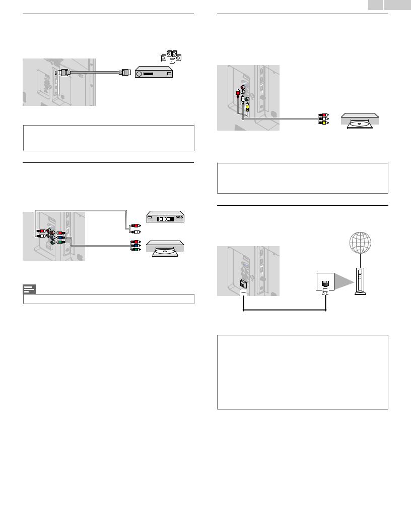
HDMI-ARC connection
HDMI-ARC allows you to use EasyLink to output TV audio directly to a connected audio device, without the need for an additional digital audio cable.
HDMI 1 IN only |
OUT |
HDMI cable |
Digital home theater |
|
|
|
amplifier that supports |
|
HDMI-ARC |
 Note(s)
•The HDMI 1 connector is HDMI Audio Return Channel (ARC) compliant. Use it to output digital audio to an HDMI home theater system.
•Be sure that the device is HDMI CEC and ARC compliant and that the TV is connected to the device using an HDMI cable attached to HDMI-ARC connectors.
Component analog video connection
Component analog video connection offers better picture quality for video devices connected to the unit.
If you connect to the unit’s component video (Y/Pb/Pr) input jacks, connect analog audio cables to the analog audio (L/R) input jacks.
Audio (L/R) cables |
OUT |
|
|
||
IN |
Set-top Box |
|
or |
||
|
||
IN |
|
|
Component (Y/Pb/Pr) |
OUT |
|
Video cables |
Blu-ray Disc / DVD |
|
|
||
|
Recorder |
Note(s)
•The unit accepts 480i, 480p, 720p, 1080i and 1080p of video signals for this connection.
16 .English
Composite analog video connection
Composite analog video connection offers standard picture quality for video devices connected to the unit.
Ifyouconnecttotheunit’scomponent/compositevideo(Y/VIDEO)input jack (green), connect audio cables to the audio (L/R) input jacks. When the audio is monaural, then only connect to the audio L input jack.
IN |
OUT |
Video + Audio(L/R) cables
DVD Player
 Note(s)
•With this unit, yellow cable must be connected to Y (green) jack on the component video input jacks.
•Whenever you connect to the composite video input jack (Y/VIDEO), you must disconnect the component video input jacks (Pb and Pr). If you leave those jacks connected, it may cause an unstable picture.
Connecting the TV to the internet using an Ethernet cable
Internet
LAN |
Ethernet cable |
Network provisioning |
equipment |
 Note(s)
•Please purchase shielded Ethernet cables at your local store and use them when you connect to network equipment.
•After connecting an Ethernet cable, set up necessary network settings. Connect to network p. 40
•Do not insert any cable other than an Ethernet cable to the Ethernet port to avoid damaging the unit.
•If your telecommunications equipment (modem, etc.) does not have broadband router functions, connect a broadband router.
•Ifyourtelecommunicationsequipment(modem,etc.)hasbroadbandrouterfunctionsbutthere is no vacant port, then add a hub.
•For a broadband router, use a router which supports 10BASE-T / 100BASE-TX.
•Do not connect your PC directly to the Ethernet port of this unit.
Continued on next page.
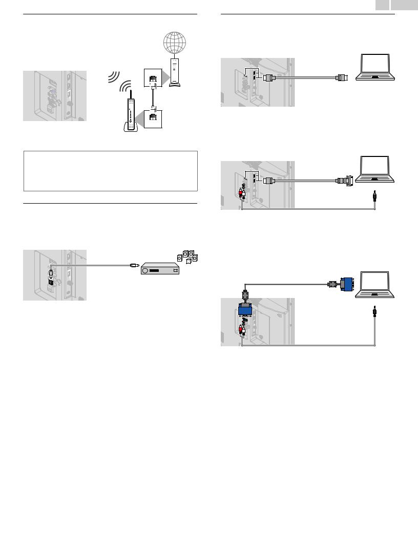
Connecting the TV to the internet using a wireless LAN
Internet
Network provisioning equipment
LAN
Ethernet cable
WLAN
Broadband router
 Note(s)
•After you make the wireless connection, set up the necessary network settings. Connect to network p. 40
•Use a wireless LAN Access Point (AP) (e.g. broadband wireless router) which supports IEEE 802.1 1 a/b/g/n/ac. (n is recommended for stable operation of the wireless network.)
•This unit does not support Ad-hoc mode.
•Other radio devices or obstacles may cause interference to the wireless network connection.
Digital audio output connection
If you connect this unit to an external digital audio device, you can enjoy multi-channel audio like 5.1ch digital broadcasting sound.
Use a digital audio optical cable to connect the unit to external digital audio devices.
|
|
IN |
OUT |
Digital Audio |
|
|
Optical cable |
Digital Home |
|
|
|
|
|
Theater Amplifier |
17 .English
PC connection
HDMI connection
This unit can be connected to your PC that has an HDMI terminal. Use an HDMI cable for this digital connection.
IN |
OUT |
HDMI cable |
PC |
HDMI-DVI connection
This unit can be connected to your PC that has a DVI terminal.
Use an HDMI-DVI conversion cable for this video digital connection and it requires stereo mini 3.5mm plug audio cable for analog audio signal as well.
|
|
OUT |
IN |
HDMI-DVI |
PC |
conversion cable |
|
|
|
OUT |
|
IN |
|
|
|
|
Stereo Mini 3.5 mm Plug Audio cable
VGA connection
This unit is equipped with a PC input jack. If you connect this unit to your PC, you can use this unit as a PC monitor.
Use a VGA cable for this video connection and it requires a stereo mini 3. 5mm plug audio cable for analog audio signal as well.
|
VGA cable |
|
PC |
IN |
OUT |
IN |
Stereo Mini 3.5 mm Plug Audio cable
Continued on next page.

18 .English
The following PC-input video signals can be displayed:
Format |
Resolution |
Refresh rate |
VGA |
640 x 480 |
|
SVGA |
800 x 600 |
|
XGA |
1,024 x 768 |
60Hz |
WXGA |
1,280 x 768 |
|
1,360 x 768 |
|
|
|
|
|
FHD |
1,920 x 1,080 |
|
UHD *1 |
3,840 x 2,160 |
24/30/60Hz *2 |
4,096 x 2,160 |
|
|
|
|
Other formats or non-standard signals will not be displayed correctly.
*1 UHD format is available only when using the HDMI connection and HDMI-DVI connection.
*2 Refresh rate for VGA connection is only 60Hz.
 Note(s)
•Please purchase a VGA cable that has a ferrite core (0.6 inches (15mm) or more in diameter).
•Please purchase a HDMI-DVI conversion cable that has a ferrite core.
•The following operations may reduce noise.
–Attach a ferrite core to the AC power cord of your PC.
–Unplug the AC power cord and use the built-in battery of your portable / laptop PC.
•Some HDMI cables and devices may not be compatible with the TV due to different HDMI specifications.
•Use an HDMI cable with the HDMI logo (a certified HDMI cable). High speed HDMI cable is recommended for the better compatibility.
•The unit accepts 480i, 480p, 720p, 1080i, 1080p and 2160p video signals only when using the HDMI connection and HDMI-DVI connection.
•HDMI-DVI connection requires separate audio connections as well and the audio signals are output as analog (L/R) audio.
•DVI does not display 480i image which is not in compliance with EIA/CEA-861/861B.
USB memory stick
This unit offers easy playback of picture, music and video files.
Insert the USB memory stick into the USB terminal shown below.
For a complete list of file formats and specifications supported, refer to
USB Section p. 26
 Note(s)
•The unit recognizes only a USB memory stick.
•Do not use a USB hub or an extension cable to connect an external hard disk drive to the unit. (Not supported.)
•Always insert a USB memory stick directly to this unit.
•A USB memory stick is not supplied with this unit.
•We do not guarantee that all USB memory sticks can be supported by this unit.
•Be sure to keep a backup copy of the original files on your USB device before you play them back on this unit. We have no responsibilities for damage or loss of your USB stored data.
•To protect your USB memory stick files from being erased place the write protect sliding tab in the protect position (if available).
•When you are ready to remove a USB memory stick, set the unit to go into standby mode to avoid any damage to your data and the unit.
•A USB memory stick that requires its own driver or the device with a special system such as fingerprint recognition are not supported.
•This unit is not allowed to use the USB memory stick which requires an external power supply (500mA or more).
Continued on next page.
Loading...