


 Loading...
65BDL4150D
V1.01
www.philips.com/welcome
User Manual (English)
65BDL4150D
Safety Instructions
Safety precautions and maintenance
WARNING:Use of controls,adjustments or procedures other than those specified in this documentation may result in exposure to shock, electrical hazards and/or mechanical hazards.
Read and follow these instructions when connecting and using your display:
Operation:
•Keep the display out of direct sunlight and away from stoves or any other heat sources.
•Remove any object that could fall into ventilation holes or prevent proper cooling of the display’s electronics.
•Do not block the ventilation holes on the cabinet.
•When positioning the display, make sure the power plug and outlet are easily accessible.
•When turning off the display by detaching the power cord, wait 6 seconds before re-attaching the power cord for normal operation.
•Ensure the use of an approved power cord provided by Philips at all times. If your power cord is missing, please contact your local service center.
•Do not subject the display to severe vibration or high impact conditions during operation.
•Do not knock or drop the display during operation or transportation.
•The eye bolt is for usage in short-time maintenance and installation.We suggest not to use the eye bolt for more than 1 hour. Prolong usage is prohibited. Please keep a clear safety area under the display while using the eye bolt.
Maintenance:
•To protect your display from possible damage, do not put excessive pressure on the LCD panel.When moving your display, grasp the frame to lift; do not lift the display by placing your hand or fingers on the LCD panel.
•Unplug the display if you are not going to use it for an extensive period of time.
•Unplug the display if you need to clean it with a slightly damp cloth.The screen may be wiped with a dry cloth when the power is off. However, never use organic solvent, such as, alcohol, or ammonia-based liquids to clean your display.
•To avoid the risk of shock or permanent damage to the set, do not expose the display to dust, rain, water or an excessively moist environment.
•If your display becomes wet, wipe it with dry cloth as soon as possible.
•If a foreign substance or water gets in your display, turn the power off immediately and disconnect the power cord.Then remove the foreign substance or water, and send the unit to the maintenance center.
•Do not store or use the display in locations exposed to heat, direct sunlight or extreme cold.
•In order to maintain the best performance of your display and ensure a longer lifetime, we strongly recommend using the display in a location that falls within the following temperature and humidity ranges.
-- Temperature: 0-40°C 32-104°F -- Humidity: 20-80% RH
•LCD panel temperature need to be 25 degrees Celsius at all time for better luminance performance.
IMPORTANT: Always activate a moving screen saver program when you leave your display unattended. Always activate a periodic screen refresh application if the unit will display unchanging static content. Uninterrupted display of still or static images over an extended period may cause “burn in”, also known as “after-imaging” or “ghost imaging”, on your screen.This is a well-known phenomenon in LCD panel technology. In most cases, the “burned in” or “after-imaging” or “ghost imaging” will disappear gradually over a period of time after the power has been switched off.
WARNING: Severe “burn-in” or “after-image” or “ghost image” symptoms will not disappear and cannot be repaired.This is also not covered under the terms of your warranty.
Service:
•The casing cover should be opened only by qualified service personnel.
•If there is any need for repair or integration, please contact your local service center.
•Do not leave your display under direct sunlight.
If your display does not operate normally, having followed the instructions set out in this document, please contact a technician or your local service center.
ii
65BDL4150D
Read and follow these instructions when connecting and using your display:
•Unplug the display if you are not going to use it for an extensive period of time.
•Unplug the display if you need to clean it with a slightly damp cloth.The screen many be wiped with a dry cloth when the power is off. However, never use alcohol, solvents or ammonia-based liquids.
•Consult a service technician if the display does not operate normally when you have followed the instructions in this manual.
•The casing cover should be opened only by qualified service personnel.
•Keep the display out of direct sunlight and away from stoves or any other heat sources.
•Remove any object that could fall into the vents or prevent proper cooling of the display’s electronics.
•Do not block the ventilation holes on the cabinet.
•Keep the display dry.To avoid electric shock, do not expose it to rain or excessive moisture.
•When turning off the display by detaching the power cable or DC power cord, wait for 6 seconds before re-attaching the power cable or DC power cord for normal operation..
•To avoid the risk of shock or permanent damage to the set do not expose the display to rain or excessive moisture.
•When positioning the display, make sure the power plug and outlet are easily accessible.
•IMPORTANT: Always activate a screen saver program during your application. If a still image in high contrast remains on the screen for an extended period of time, it may leave an ‘after-image’ or ‘ghost image’ on the front of the screen.This is a well-known phenomenon that is caused by the shortcomings inherent in LCD technology. In most cases the afterimage will disappear gradually over a period of time after the power has been switched off. Be aware that the after-image symptom cannot be repaired and is not covered under warranty.
EU Declaration of Conformity
This device complies with the requirements set out in the Council Directive on the Approximation of the Laws of the Member States relating to Electromagnetic Compatibility (2014/30/EU), Low-voltage Directive (2014/35/EU), RoHS directive (2011/65/EU), and Radio Equipment Directive (2014/53/ EU).
This product has been tested and found to comply with the harmonized standards for Information Technology Equipment, these harmonized standards published under Directives of Official Journal of the European Union.
ESD Warnings
When user close to the monitor may cause the equipment discharge and reboot to the display of main menu.
Warning:
This equipment is compliant with Class A of EN55032/CISPR 32. In a residential environment this equipment may cause radio interference.
Federal Communications Commission (FCC) Notice (U.S. Only)
NOTE: This equipment has been tested and found to comply with the limits for a Class A digital device, pursuant to part 15 of the FCC Rules.These limits are designed to provide reasonable protection against harmful interference when the equipment is operated in a commercial environment.This equipment generates, uses, and can radiate radio frequency energy and, if not installed and used in accordance with the instruction manual, may cause harmful interference to radio communications. Operation of this equipment in a residential area is likely to cause harmful interference in which case the user will be required to correct the interference at his own expense.
Changes or modifications not expressly approved by the party responsible for compliance could void the user’s authority to operate the equipment.
Use only an RF shielded cable that was supplied with the display when connecting this display to a computer device.
To prevent damage which may result in fire or shock hazard, do not expose this appliance to rain or excessive moisture.
This device complies with Part 15 of the FCC Rules. Operation is subject to the following two conditions: (1) This device may not cause harmful interference, and (2) this device must accept any interference received, including interference that may cause undesired operation.
Envision Peripherals Inc.
490 N McCarthy Blvd, Suite #120 Milpitas, CA 95035
USA
iii
65BDL4150D
Europe – EU Declaration of Conformity
This device complies with the essential requirements of the Radio Equipment Directive (2014/53/EU).The following test methods have been applied in order to prove presumption of conformity with the essential requirements of the Radio Equipment Directive (2014/53/EU):
- EN60950-1/EN62311/EN300328/EN301893/EN301489
Europe Statement
IMPORTANT NOTE:
The device is restricted to indoor use only when operating in the 5150 to 5350MHz frequency range.
|
AT |
BE |
BG |
HR |
CY |
CZ |
DK |
|
|
|
|
|
|
|
|
|
EE |
FI |
FR |
DE |
EL |
HU |
IE |
|
|
|
|
|
|
|
|
|
IT |
LV |
LT |
LU |
MT |
NL |
PL |
|
|
|
|
|
|
|
|
|
PT |
RO |
SK |
SI |
ES |
SE |
UK |
|
|
|
|
|
|
|
|
Radiation Exposure Statement:
This equipment complies with CE radiation exposure limits set forth for an uncontrolled environment.This equipment should be installed and operated with minimum distance 20cm between the radiator & body.
The frequency, mode and the maximum transmitted power in EU are listed below: 2412-2472MHz(802.11g 6Mbps): 19.98dBm
2402-2480MHz (EDR 3Mbps): 9.65dBm
2402-2480MHz (LE 1Mbps): 9.80dBm
5180-5240/5260-5320/5500-5700MHz (802.11 ac VHT40 MCS0/NSS1): 22.95dBm
Taiwan:
大功率或變更原設計之特性及功能。
並改善至無干擾時方得繼續使用。
Caution:
Any changes or modifications not expressly approved by the party responsible for compliance could void the user’s authority to operate this equipment. This transmitter must not be co-located or operating in conjunction with any other antenna or transmitter.
Operations in the 5GHz products are restricted to indoor usage only.
Radiation Exposure Statement:
This equipment complies with FCC radiation exposure limits set forth for an uncontrolled environment.This equipment should be installed and operated with minimum distance 20cm between the radiator & your body.
iv
65BDL4150D
Canada:
Industry Canada statement:
This device complies with RSS-247 of the Industry Canada Rules. Operation is subject to the following two conditions: (1) This device may not cause harmful interference, and (2) this device must accept any interference received, including interference that may cause undesired operation.
Ce dispositif est conforme à la norme CNR-247 d’Industrie Canada applicable aux appareils radio exempts de licence. Son fonctionnement est sujet aux deux conditions suivantes: (1) le dispositif ne doit pas produire de brouillage préjudiciable, et (2) ce dispositif doit accepter tout brouillage reçu, y compris un brouillage susceptible de provoquer un fonctionnement indésirable.
Radiation Exposure Statement:
This equipment complies with ISED radiation exposure limits set forth for an uncontrolled environment.This equipment should be installed and operated with minimum distance 20cm between the radiator & your body.
Déclaration d’exposition aux radiations:Cet équipement est conforme aux limites d’exposition aux rayonnements ISED établies pour un environnement non contrôlé. Cet équipement doit être installé et utilisé avec un minimum de 20 cm de distance entre la source de rayonnement et votre corps.
Polish Center forTesting and Certification Notice
The equipment should draw power from a socket with an attached protection circuit (a three-prong socket). All equipment that works together (computer, display, printer, and so on) should have the same power supply source.
The phasing conductor of the room’s electrical installation should have a reserve short-circuit protection device in the form of a fuse with a nominal value no larger than 16 amperes (A).
To completely switch off the equipment, the power supply cable must be removed from the power supply socket, which should be located near the equipment and easily accessible.
A protection mark “B” confirms that the equipment is in compliance with the protection usage requirements of standards PN-93/T-42107 and PN-89/ E-06251.
v
65BDL4150D
Electric, Magnetic and Electromagnetic Fields (“EMF”)
1.We manufacture and sell many products targeted at consumers, which, like any electronic apparatus, in general have the ability to emit and receive electromagnetic signals.
2.One of our leading Business Principles is to take all necessary health and safety measures for our products, to comply with all applicable legal requirements and to stay well within the EMF standards applicable at the time of producing the products.
3.We are committed to develop, produce and market products that cause no adverse health effects.
4.We confirm that if its products are handled properly for their intended use, they are safe to use according to scientific evidence available today.
5.We play an active role in the development of international EMF and safety standards, enabling us to anticipate further developments in standardization for early integration in its products.
Information for U.K. only
(B) |
(A) |
WARNING -THIS APPLIANCE MUST BE EARTHED. Important:
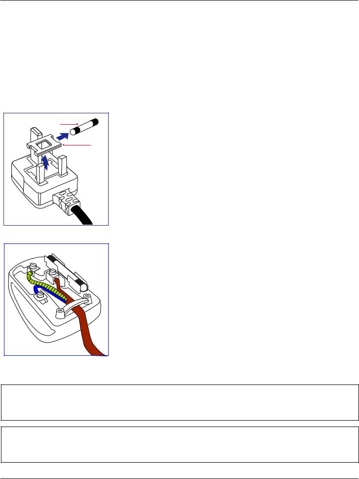
This apparatus is supplied with an approved moulded 13A plug.To change a fuse in this type of plug proceed as follows:+
1.Remove fuse cover and fuse.
2.Fit new fuse which should be a BS 1362 5A,A.S.T.A. or BSI approved type.
3.Refit the fuse cover.
If the fitted plug is not suitable for your socket outlets, it should be cut off and an appropriate 3-pin plug fitted in its place.
If the mains plug contains a fuse, this should have a value of 5A. If a plug without a fuse is used, the fuse at the distribution board should not be greater than 5A.
NOTE: The severed plug must be destroyed to avoid a possible shock hazard should it be inserted into a 13A socket elsewhere.
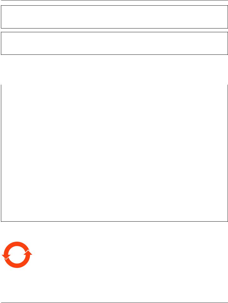
How to connect a plug
The wires in the mains lead are coloured in accordance with the following code: BLUE - “NEUTRAL” (“N”)
BROWN - “LIVE” (“L”)
GREEN & YELLOW - “EARTH” (“E”)
1. The GREEN & YELLOW wire must be connected to the terminal in the plug which is marked with the letter “E” or by the Earth symbol or coloured GREEN or GREEN & YELLOW.
2.The BLUE wire must be connected to the terminal which is marked with the letter “N” or coloured BLACK.
3.The BROWN wire must be connected to the terminal which marked with the letter “L” or coloured RED.
Before replacing the plug cover, make certain that the cord grip is clamped over the sheath of the lead - not simply over the three wires.
North Europe (Nordic Countries) Information
Placering/Ventilation
VARNING:
FÖRSÄKRA DIG OM ATT HUVUDBRYTARE OCH UTTAG ÄR LÄTÅTKOMLIGA, NÄR DU STÄLLER DIN UTRUSTNING PÅPLATS.
Placering/Ventilation
ADVARSEL:
SØRG VED PLACERINGEN FOR, AT NETLEDNINGENS STIK OG STIKKONTAKT ER NEMT TILGÆNGELIGE.
vi
65BDL4150D
Paikka/Ilmankierto
VAROITUS:
SIJOITA LAITE SITEN, ETTÄ VERKKOJOHTO VOIDAAN TARVITTAESSA HELPOSTI IRROTTAA PISTORASIASTA.
Plassering/Ventilasjon
ADVARSEL:
NÅR DETTE UTSTYRET PLASSERES, MÅ DU PASSE PÅ AT KONTAKTENE FOR STØMTILFØRSEL ER LETTE Å NÅ.
China RoHS
质的名称和含量。
|
|
|
|
|
|
|
|
|
|
|
|
|
|
|
|
|
|
|
|
|
|
|
|
|
|
||||||
|
(Pb) |
(Hg) |
(Cd) |
|
(Cr (VI)) |
(PBB) |
(PBDE) |
|
|
|
|
|
|
|
|
|
○ |
○ |
○ |
|
○ |
○ |
○ |
|
|
|
|
|
|
|
|
|
× |
○ |
○ |
|
○ |
○ |
○ |
|
|
|
|
|
|
|
|
* |
× |
○ |
○ |
|
○ |
○ |
○ |
|
|
|
|
|
|
|
|
|
× |
○ |
○ |
|
○ |
○ |
○ |
|
|
|
|
|
|
|
|
/ |
× |
○ |
○ |
|
○ |
○ |
○ |
|
|
|
|
|
|
|
|
|
X |
○ |
○ |
|
○ |
○ |
○ |
|
|
|
|
|
|
|
|
SJ/T 11364
*: O: GB/T 26572 X: GB/T 26572
“×” GB/T 26572 RoHS
10
( )
vii

65BDL4150D
$
|
|
|
|
|
|
||
|
|
|
|
|
|
|
|
|
|
|
|
|
|
||
|
|||||||
|
(Pb) |
(Hg) |
(Cd) |
(Cr+6) |
(PBB) |
(PBDE) |
|
|
○ |
○ |
○ |
○ |
○ |
○ |
|
|
|
|
|
|
|
|
|
|
○ |
○ |
○ |
○ |
○ |
○ |
|
|
|
|
|
|
|
|
|
|
|
○ |
○ |
○ |
○ |
○ |
|
|
|
|
|
|
|
|
|
|
|
○ |
○ |
○ |
○ |
○ |
|
|
|
|
|
|
|
|
|
|
○ |
○ |
○ |
○ |
○ |
○ |
|
|
|
|
|
|
|
|
|
|
|
○ |
○ |
○ |
○ |
○ |
|
|
|
|
|
|
|
|
|
|
|
○ |
○ |
○ |
○ |
○ |
|
|
|
|
|
|
|
|
|
|
|
○ |
○ |
○ |
○ |
○ |
|
|
|
|
|
|
|
|
|
|
|
○ |
○ |
○ |
○ |
○ |
|
|
|
|
|
|
|
|
|
|
|
○ |
○ |
○ |
○ |
○ |
|
|
|
|
|
|
|
|
|
1. ○2.
:
:
(1)30 10
(2)2 2 1
:
, , , ,
Turkey RoHS:
Türkiye Cumhuriyeti: EEE Yönetmeliğine Uygundur
Ukraine RoHS:
Обладнання відповідає вимогам Технічного регламенту щодо обмеження використання деяких небезпечних речовин в електричному та електронному обладнанні, затвердженого постановою Кабінету Міністрів України від 3 грудня 2008 № 1057
viii
65BDL4150D
End-of-Life Disposal
Your new Public Information Display contains materials that can be recycled and reused. Specialized companies can recycle your product to increase the amount of reusable materials and to minimize the amount to be disposed of.
Please find out about the local regulations on how to dispose of your old display from your local Philips dealer.
(For customers in Canada and U.S.A.)
This product may contain lead and/or mercury. Dispose of in accordance to local-state and federal regulations. For additional information on recycling contact www.eia.org (Consumer Education Initiative)
Waste Electrical and Electronic Equipment-WEEE
Attention users in European Union private households
This marking on the product or on its packaging illustrates that, under European Directive 2012/19/EU governing used electrical and electronic appliances, this product may not be disposed of with normal household waste.You are responsible for disposal of this equipment through a designated waste electrical and electronic equipment collection.To determine the locations for dropping off such waste electrical and electronic, contact your local government office, the waste disposal organization that serves your household or the store at which you purchased the product.
Attention users in United States:
Please dispose of according to all Local, State and Federal Laws. For the disposal or recycling information, contact: www.mygreenelectronics.com or www.eiae.org.
End of Life Directives-Recycling
Your new Public Information Display contains several materials that can be recycled for new users.
Please dispose of according to all Local, State, and Federal laws.
As an ENERGY STAR Partner, we have determined that this product meets the ENERGY STAR guidelines for energy efficiency.
Restriction on Hazardous Substances statement (India)
This product complies with the “E-Waste (Management) Rules, 2016” CHAPTER V, rule 16, sub-rule (1) .Whereas New Electrical and Electronic Equipment and their components or consumables or parts or spares do not contain Lead, Mercury, Cadmium, Hexavalent Chromium, polybrominated biphenyls and polybrominated diphenyl ethers beyond a maximum concentration value of 0.1% by weight in homogenous materials for lead, mercury, hexavalent chromium, polybrominated biphenyls and polybrominated diphenyl ethers and of 0.01% by weight in homogenous materials for cadmium. except of exemptions set in Schedule 2 of the Rule.
E-Waste Declaration for India
This symbol on the product or on its packaging indicates that this product must not be disposed of with your other household waste. Instead it is your responsibility to dispose of your waste equipment by handing it over to a designated collection point for the recycling of waste electrical and electronic equipment .The separate collection and recycling of your waste equipment at the time of disposal will help to conserve natural resources and ensure that it is recycled in a manner that protects human health and the environment. For more information about E -waste please visit http://www.india.philips.com/about/sustainability/recycling/index.page and to know where you can drop off your waste equipment for recycling in India please contact on below given contact details.
Helpline number: 1800-425-6396 (Monday to Saturday, 9 a.m. to 5:30 pm)
E-mail: india.callcentre@tpv-tech.com
ix
65BDL4150D
Batteries
For EU:The crossed-out wheeled bin implies that used batteries should not be put to the general household waste! There is a separate collection system for used batteries, to allow proper treatment and recycling in accordance with legislation.
Please contact your local authority for details on the collection and recycling schemes. For Switzerland:The used battery is to be returned to the selling point.
For other non-EU countries: Please contact your local authority for correct method of disposal of the used battery.
According to EU directive 2006/66/EC, the battery can’t be disposed improperly.The battery shall be separated to collect by local service.
Após o uso, as pilhas e/ou baterias deverão ser entregues ao estabelecimento comercial ou rede de assistência técnica autorizada.
Information for EAC |
|
|
|
|
|
Month and year of manufacturing |
please refer information in Rating label. |
|
|
|
|
Name and location of manufacturer |
ООО“Профтехника” |
|
Адрес:3-й Проезд Марьиной рощи,40/1 офис 1.Москва,127018,Россия |
||
|
||
|
|
|
|
Наименование организации:ООО“Профтехника” |
|
|
Адрес:3-й Проезд Марьиной рощи,40/1 офис 1.Москва,127018,Россия |
|
Importer and information |
Контактное лицо:Наталья Астафьева, |
|
|
+7 495 640 20 20 |
|
|
nat@profdisplays.ru |
Information for FAC:
“Подтверждение соответствия Мининформсвязи России: Декларация соответствия № Д-PD-4342 от 01.09.2016 года, действительна до 01.09.2024 года, зарегистрирована в Федеральном агенстве связи 14.09.2016 года”
x
65BDL4150D
Table Of Contents
1. |
Unpacking and Installation........................................................ |
1 |
|
|
1.1. |
Transportation and Unpacking............................................. |
1 |
|
1.2. |
Package Contents........................................................................ |
4 |
|
1.3. |
Installation Notes......................................................................... |
4 |
|
1.4. |
Mounting on a Wall..................................................................... |
5 |
|
1.5. Mounting in Portrait Orientation........................................ |
6 |
|
|
1.6. Installing the optional table stand........................................ |
7 |
|
2. |
Parts and Functions................................................................... |
8 |
|
|
2.1. |
Control Panel................................................................................. |
8 |
|
2.2. |
Input/Output Terminals............................................................. |
9 |
|
2.3. |
Remote Control........................................................................ |
11 |
|
2.4. |
SD card Cover............................................................................ |
15 |
|
2.5. |
4G Module.................................................................................... |
15 |
3. |
Connecting External Equipment.......................................... |
16 |
|
3.1.Connecting External Equipment (DVD/VCR/
|
VCD)................................................................................................ |
16 |
3.2. |
Connecting a PC....................................................................... |
16 |
3.3. |
Connecting Audio Equipment........................................... |
17 |
3.4.Connecting Multiple Displays in a Daisy-chain
|
|
Configuration .............................................................................. |
18 |
|
3.5. |
IR connection .............................................................................. |
19 |
|
3.6. |
IR Pass - through Connection ............................................... |
20 |
4. |
Operation................................................................................. |
21 |
|
|
4.1. |
Watch the Connected Video Source ............................ |
21 |
|
4.2. |
Change Picture Format .......................................................... |
21 |
|
4.3. |
Overview ....................................................................................... |
21 |
|
4.4. |
Media Player ................................................................................. |
23 |
|
4.5. |
Browser ........................................................................................... |
26 |
|
4.6. |
PDF Player ..................................................................................... |
29 |
|
4.7. |
CMND & Play ............................................................................. |
31 |
|
4.8. |
Custom App ................................................................................. |
31 |
5. |
Setting |
........................................................................................ |
33 |
|
5.1. |
Wi - Fi ............................................................................................... |
33 |
|
5.2. .......................................................................................... |
Ethernet |
33 |
5.3.More (available when 4G module is connected)...33
5.4. |
Signage Display........................................................................... |
33 |
5.5. |
Display............................................................................................. |
41 |
5.6. |
Apps.................................................................................................. |
41 |
5.7. |
Security........................................................................................... |
41 |
5.8. |
Date & time.................................................................................. |
42 |
5.9. |
Developer options................................................................... |
42 |
5.10. |
About............................................................................................... |
42 |
5.11. |
Supplementary............................................................................ |
43 |
6. |
OSD Menu................................................................................ |
45 |
|
|
6.1. |
Navigating the OSD Menu................................................. |
45 |
|
6.2. |
OSD Menu Overview............................................................ |
45 |
7. |
Supported Media Formats..................................................... |
54 |
|
8. |
Input Mode............................................................................... |
56 |
|
9. |
Pixel Defect Policy.................................................................. |
58 |
|
|
9.1. |
Pixels and Sub-Pixels............................................................... |
58 |
|
9.2. |
Types of Pixel Defects + Dot Definition..................... |
58 |
|
9.3. |
Bright Dot Defects................................................................... |
58 |
|
9.4. |
Dark Dot Defects..................................................................... |
59 |
|
9.5. |
Proximity of Pixel Defects.................................................... |
59 |
|
9.6. |
Pixel Defect Tolerances.......................................................... |
59 |
|
9.7. |
MURA.............................................................................................. |
59 |
10. |
Cleaning and Troubleshooting.............................................. |
60 |
|
|
10.1. |
Cleaning.......................................................................................... |
60 |
|
10.2. |
Troubleshooting......................................................................... |
61 |
11. |
Technical Specifications.......................................................... |
63 |
|
xi
65BDL4150D
1.Unpacking and Installation
1.1.Transportation and Unpacking
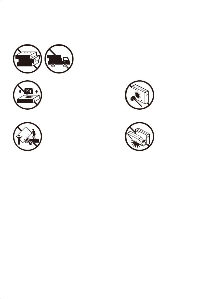
Notice for transportation
•Always keep the carton in a vertical position. Do NOT place the carton in any other direction.
|
|
|
|
|
|
|
|
|
|
|
|
|
|
|
|
|
|
|
|
|
|
|
|
|
|
|
|
|
|
|
|
|
|
|
|
|
|
|
|
|
|
|
|
|
|
|
|
|
|
|
|
|
|
|
|
|
|
|
|
|
|
|
|
|
|
|
|
|
|
|
|
|
|
|
|
|
|
|
|
|
|
|
|
|
|
|
|
|
|
|
|
|
|
|
|
|
|
|
|
|
|
|
|
|
• Do NOT place any object on the carton. |
• Do NOT apply shock/vibration to the product. |
|||||||||||||
|
|
|
|
|
|
|
|
|
|
|
|
|
|
|
|
|
|
|
|
|
|
|
|
|
|
|
|
|
|
• Move the carton by stacker.
•Do NOT drop the product. Strong impacts may damage the components inside.
1
65BDL4150D
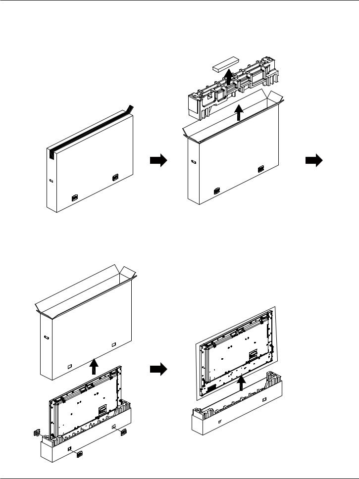
Notice for transportation
1.Remove the strap around the carton.
2.Use a blade to cut the tape on the top and open the carton.
3.Take out the cushions carefully.
4.Remove the plastic carton lockers and the top carton.
2

65BDL4150D
5. Move the display from the carton by two adults with both hands.
•Do not touch the screen of display to avoid possible scratches. Move the display by holding the handles.
• Keep the display vertically when moving it.
90° |
90° |
• Place the display vertically and its weight should spread evenly on the surface.
3

65BDL4150D
Before installing the display
•This product is packed in a carton, together with the standard accessories.
•Any other optional accessories will be packed separately.
•Move the display by at least two (2) adults.
•After opening the carton, ensure that the contents are complete and in good condition.
1.2.Package Contents
Please verify that you received the following items with your package content:
•LCD display
•Quick start guide
•Remote Control and AAA batteries
•Power cord
•RS232 cable
•RS232 daisy chain cable
•IR sensor cable
•HDMI cable
•Dipole Antenna x2
•SD card cover x1
•M3 screw x1
•M2 screw x2
•Logo
Quick start guide 

 Remote Control and AAA Batteries
* The supplied power cord varies depending on destination.
Power Cord |
RS232 Cable |
RS232 Daisy Chain Cable |
IR Sensor Cable |
HDMI Cable |
Dipole Antenna x2 |
SD card cover M3 |
M2 |
Logo |
*Items may differ in different locations
*Display design and accessories may differ from the images shown..
NOTES:
•For all other regions, apply a power cord that conforms to the AC voltage of the power socket and has been approved by and complies with the
safety regulations of the particular country (Type H05W-F, 2G or 3G, 0.75 or 1 mm2 should be used).
•Keep the packaging materials appropriately after unpacking the product.
1.3.Installation Notes
•Only use the power cable provided with this product. If an extension cord is required, please consult your service agent.
•The product should be installed on a flat surface, or the product may tip over. Leave a space between the rear of the product and the wall for proper ventilation. Do not install the product in a kitchen, bathroom or a place exposed to moisture, failure to do so may shorten the life of the internal parts.
•Do not install the product where it is 3000m and higher in altitude. Failure to do so may result in malfunctions.
4
65BDL4150D
1.4.Mounting on a Wall
To mount this display on a wall, a standard wall-mounting kit (commercially available) is required. It is recommended that you use a mounting interface that complied with TUV-GS and /or UL1678 standard in North America.
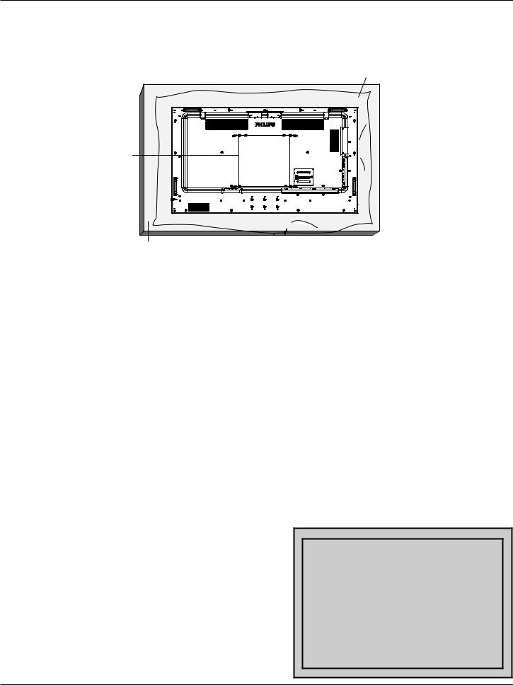
Protective Sheet
VESA Grid
Table
1.Prepare a flat and horizontal surface that is larger than the display and spread a thick protective sheet on it to facilitate your operation without scratching the screen.
2.Ensure you have all accessories for all types of mounting (wall mount, ceiling mount, table stand, etc).
3.Follow the instructions that came with the base mounting kit. Failure to follow the correct mounting procedures could result in damage to the equipment, or injury to the user or installer.The product warranty does not cover the damage caused by improper installation.
4.For the wall-mounting kit, use the M6 mounting screws (with a length 10 mm longer than the thickness of the mounting bracket) and tighten them securely.
5.Weight of the unit without base=36.5 kg.The equipment and its associated mounting facilities still remain secure during the test. Use only the UL listed Wall Mount Bracket with a minimum weight/load of 36.5 kg.
1.4.1. VESA Grid
65BDL4150D |
400(H) x 400(V) mm |
Caution:
To prevent the display from falling:
•For wall or ceiling mounting, we recommend that you install the display with metal brackets which are commercially available. For detailed instructions about the installation, refer to the guide provided with the bracket.
•To prevent the display from falling in case of earthquake or other natural disaster, please consult the manufacturer of the bracket for the mounting location.
•As this product is high and heavy, the installation of this product is recommended to be performed by four technicians.
Ventilation Requirements for enclosure locating
Leave a space of 100 mm at the top, rear, right and left of the display for ventilation.
|
100 mm |
100 mm |
100 mm |
|
100 mm |
5
65BDL4150D
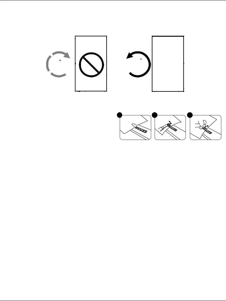
1.5.Mounting in Portrait Orientation
This display can be installed in portrait position.
1.If the table stand is attached, remove it first.
2.Rotate the display counter-clockwise by 90°.The “


 ” logo should be on the RIGHT side when facing the display.
90 |
90 |
1.5.1. How to remove the logo
1. Prepare a piece of paper with a cutting area of logo as a protector to |
1 |
2 |
3 |
|
prevent the front bezel from scratching. |
||||
|
|
|
2. Use a knife and carefully remove the logo sticker with the paper placing beneath.
3. Tear off the logo sticker.
NOTE: We recommend you contact a professional technician when installing the display on a wall.We are not responsible for any damage to the product if the installation is not performed by a professional technician.
6
65BDL4150D
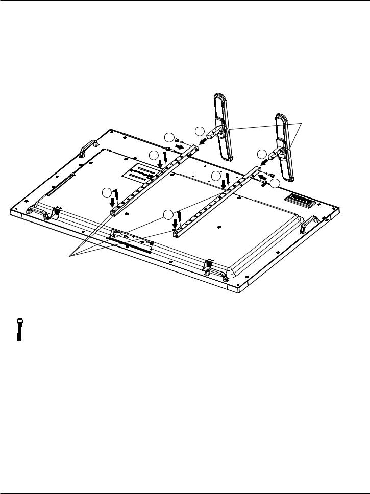
1.6.Installing the optional table stand
1.You can order the optional table stand for this display by the Model Number: BM05922.
2.Installing process:
(1)Ensure the display is powered off.
(2)Spread a protective sheet on a flat surface.
(3)Hold the handles and place the display face-down on the protective sheet.
(4)Assemble the tube to the display as shown below.
(5)Insert the stand to the tube and fix the stand by using the thumb screw.
1 


Fasten the longest screw (Length=50mm) in Hole #2 & Hole#12 of tube to fix it on the display.
|
3 |
2 |
|
|
|
1 |
|
2 |
|
|
1 |
|
|
3 |
|
1 |
|
Make sure to have the small step facing the front of the display.
NOTE:
Screws longest length=50mm
There are 4 kinds of screw in the package.
Please use the longest one to fix the universal stand.
7
65BDL4150D
2.Parts and Functions
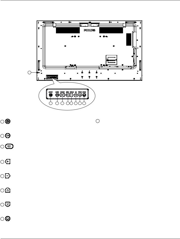
2.1.Control Panel
9
1 |
2 |
3 |
4 |
5 |
6 |
7 |
8 |
1
Use this button to turn the display on or put the display to standby mode.
2
Switch the audio mute ON/OFF.
3
Choose the input source.
•Used as [OK] button in the On-Screen-Display menu.
4
Increase the adjustment while OSD menu is on, or increase the audio output level while OSD menu is off.
5
Decrease the adjustment while OSD menu is on, or decrease the audio output level while OSD menu is off.
6
Move the highlight bar up to adjust the selected item while OSD menu is on.
7
Move the highlight bar down to adjust the selected item while OSD menu is on.
8
Return to previous menu while OSD menu is on, or to activate the OSD menu when OSD menu is off.
9Remote control sensor and power status indicator
•Receives command signals from the remote control.
•Indicates the operating status of the display without OPS: -- Lights green when the display is turned on
-- Lights red when the display is in standby mode
-- When {SCHEDULE} is enabled, the light blinks green and red
-- If the light blinks red, it indicates that a failure has been detected
-- Lights off when the main power of the display is turned off
* Use an IR sensor cable for better remote control performance. (Please refer to the instructions on 3.5)
8
65BDL4150D
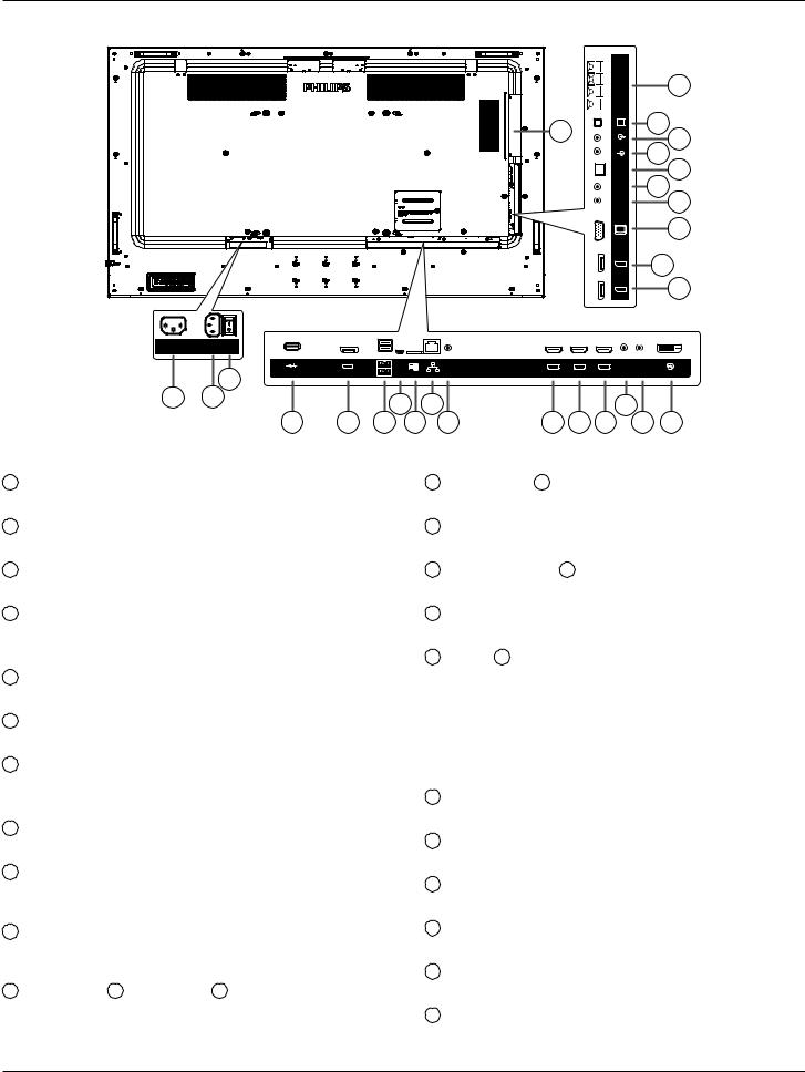
2.2.Input/Output Terminals
100-240V
50-60Hz 2.5A
|
|
USB 2.0 |
3 |
USB |
DP OUT |
Service Port |
||
|
|
USB 3.0 |
1 2
4 5 6
1AC OUT
AC power supply to the AC IN jack of a media player.
2AC IN
AC power input from the wall outlet.
3MAIN POWER SWITCH
Switch the main power on/off.
4USB SERVICE PORT
Connect to USB storage for main board Firmware update. NOTE: It’s for updating firmware only.
5DisplayPort OUT
Android DisplayPort out.
6USB PORT
Connect your USB storage device.
7USB SERVICE PORT
Connect to USB storage for Android ADB Firmware update. NOTE: It’s for updating firmware only.
8MICRO SD CARD
Connect your MICRO SD CARD.
9RJ-45
LAN control function for the use of remote control signal from control center.t for installing the optional OPS module
10RS232C
Android RS232 network input reserved for customized protocol usage from System Integrator.
11HDMI1 IN / 12 HDMI2 IN / 13 HDMI3 IN
HDMI video/audio input.
|
|
|
|
|
EXT. SPK |
|
|
26 |
|
|
|
|
|
|
TERMINAL |
|
|
|
|
|
|
27 |
|
|
SPEAKER |
25 |
24 |
||
|
|
|
|
|
SWITCH |
||||
|
|
|
|
|
AUDIO OUT |
23 |
|||
|
|
|
|
|
AUDIO IN |
||||
|
|
|
|
|
SPDIF |
|
|
22 |
|
|
|
|
|
|
OUT |
21 |
|
||
|
|
|
|
|
IR-OUT |
20 |
|||
|
|
|
|
|
IR-IN |
|
|
||
|
|
|
|
|
VGA IN |
|
|
19 |
|
|
|
|
|
|
DP OUT |
|
18 |
||
|
|
|
|
|
DP IN |
|
|
17 |
|
OTG |
RS232 |
|
|
|
RS232 |
RS232 |
|
|
|
HDMI1 IN |
HDMI2 IN |
HDMI3 IN |
IN |
OUT |
DVI IN |
||||
MICRO SD |
LAN |
||||||||
|
|
|
|
|
|
|
|||
7 |
9 |
|
|
|
14 |
|
|
||
8 |
10 |
11 12 13 |
15 |
16 |
|||||
14RS232C IN / 15 RS232C OUT
RS232C network input / output for the loop-through function.
16DVI IN
DVI-D video input.
17DisplayPort IN / 18 DisplayPort OUT
DisplayPort video input / output.
19VGA IN (D-Sub)
VGA video input.
20IR IN / 21 IR OUT
IR signal input / output for the loop-through function.
NOTES:
•This display’s remote control sensor will stop working if the jack [IR IN] is connected.
•To remotely control your A/V device via this display, refer to page 20 for IR Pass Through connection.
22SPDIF OUT
Digital audio output
23AUDIO IN
Audio input for VGA source (3.5mm stereo phone).
24AUDIO OUT
Audio output to external AV device.
25SPEAKER SWITCH
Internal speaker on/off switch.
26SPEAKERS OUT
Audio output to external speakers.
27OPS SLOT
Slot for installing the optional OPS module that use fire enclosure.
9
65BDL4150D
2.2.1. Inserting the batteries in the remote control
The remote control is powered by two 1.5V AAA batteries.
To install or replace the batteries:
1. Press and then slide the cover to open it.
2. Insert the batteries with the correct polarity (+) and (–). 3. Replace the cover.
Caution:
Incorrect use of batteries may cause leakage or explosion. Be sure to follow the instructions below:
•Insert “AAA” batteries with the correct polarity (+ and -).
•Do not mix battery types.
•Do not use a new battery with a used one together. Otherwise, it may cause leakage or shorten the life of the batteries.
•Remove the dead batteries immediately to avoid battery leakage in the battery compartment. Do not touch exposed battery acid, as it may cause injury to your skin.
NOTE: Remove the batteries from the battery compartment when not using for an extended period of time.
2.2.2. Handling the remote control
• Do not drop or apply shock to the remote control.
• Do not allow any liquid to get inside the remote control. If water has entered the remote control, wipe the remote control with a dry cloth immediately.
• Do not place the remote control near heat and steam sources.
• Do not attempt to disassemble the remote control, unless you need to place batteries in the remote control.
2.2.3. Operating range of the remote control
Point the top front of the remote control at the remote sensor on the display when you press the buttons.
Use the remote control within a distance of less than 5m/16ft from the display’s sensor, and a horizontal and vertical angle of less than 30°.
NOTE:
1.The remote control may not function properly when the remote control sensor on the display is under direct sunlight or strong illumination, or when there is an object between the remote control and the remote sensor of the display.
2.Push out the lens to have better remote control performance and easy to observe the light
information of power status. |
30 |
30 |
3. Pull back the lens before mounting the display for video wall application. 4. Pull/Push the lens until hearing the click sound.
10
65BDL4150D
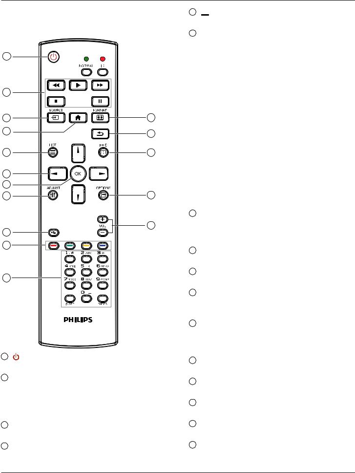
2.3.Remote Control
2.3.1. General functions
1 |
|
|
2 |
|
|
3 |
|
12 |
4 |
|
13 |
|
|
|
5 |
|
14 |
6 |
|
|
7 |
|
|
8 |
|
15 |
9 |
|
16 |
|
|
|
10 |
|
|
11 |
|
|
1 |
[ |
] POWER button |
|
Turn the power On/Off. |
|
2[PLAY] buttons
Control playback of media files.(for Media Input only)
Freeze feature
Pause: hot key for freezing all inputs content. Play: hot key for unfreezing all input content.
3[ ] SOURCE button
Root Menu: Go to the OSD of Video source.
4[ ] HOME button
Root Menu: Go to the OSD of Main Menu. Others: Exit from the OSD.
5[ ] LIST button
Reserved.
6NAVIGATION buttons [ ]
]
Root Menu: Go to the OSD of Smart picture.
Main Menu: Move the selected item up to make adjustment.
IR Daisy Chain Menu: Increase the controlled Group ID number.
[ ]
]
Root Menu: Go to the OSD of Audio source.
Main Menu: Move the selected item bar down to make adjustment. IR Daisy Chain Menu: Decrease the controlled Group ID number.
[ ]
]
Main Menu: Go to the previous level of menu. Source Menu: Exit from the source menu. Volume Menu: Decrease the volume.
[ ]
]
Main Menu: Go to the next level of menu or set selected option. Source Menu: Go to the selected source.
Volume Menu: Increase the volume.
7[ ] button
Root Menu: Go to the OSD of IR daisy chain in Primary/Secondary mode.
Main Menu: Confirm an entry or selection.
8[
 ] ADJUST button
Go to the OSD of Auto Adjust (for VGA only).
9[ ] MUTE button
Sound mute on or off.
10[ ] [
] [ ] [
] [ ] [
] [ ] COLOR buttons
Choose a task or option. (for Media Input only) [ ] Hot key for Window selection function.
11[Number/ ID SET/ ENTER] button
Enter text for network setting.
Press to set the display ID. Refer to 2.3.2. ID Remote Control for more details.
12[ ] FORMAT button
Change Image Zoom Mode [Full][4:3][1:1][16:9][21:9][Custom].
13[ ] BACK button
Return to the previous page or exit from the previous function.
14[ ] INFO button
Show Information OSD.
15[ ] OPTIONS button
Reserved.
16[ ] [
] [ ] VOLUME button
Adjust volume level.
11
65BDL4150D
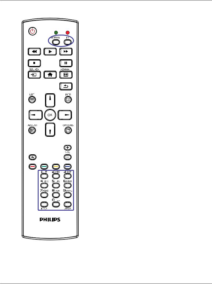
2.3.2. ID Remote Control
Set remote control ID number when using several displays.
Press the [ID] button and the red LED blinks twice.
1.Press [ID SET] button for more than 1 second to enter the ID Mode.The red LED lights up.
Press the [ID SET] button again will exit the ID Mode.The red LED lights off.
Press the digit numbers [0] ~ [9] to select the display to be controlled. For example: press [0] and [1] for display No.1, press [1] and [1] for display No.11.
The numbers available are [01] ~ [255].
2.If no button is pressed within 10 seconds, it will exit from the ID mode.
3.If a wrong button is pressed, wait for 1 second until the red LED lights off and then turns on again, then press the correct digits.
4.Press [ENTER] button to confirm your selection.The red LED blinks twice and then lights off.
NOTE:
•Press [NORMAL] button.The green LED blinks twice, indicating that the display is under normal operation.
•It is necessary to set up the ID number for each display before selecting its ID number.
12
Loading...