


Dryview 5800
Table of contents
 Loading...
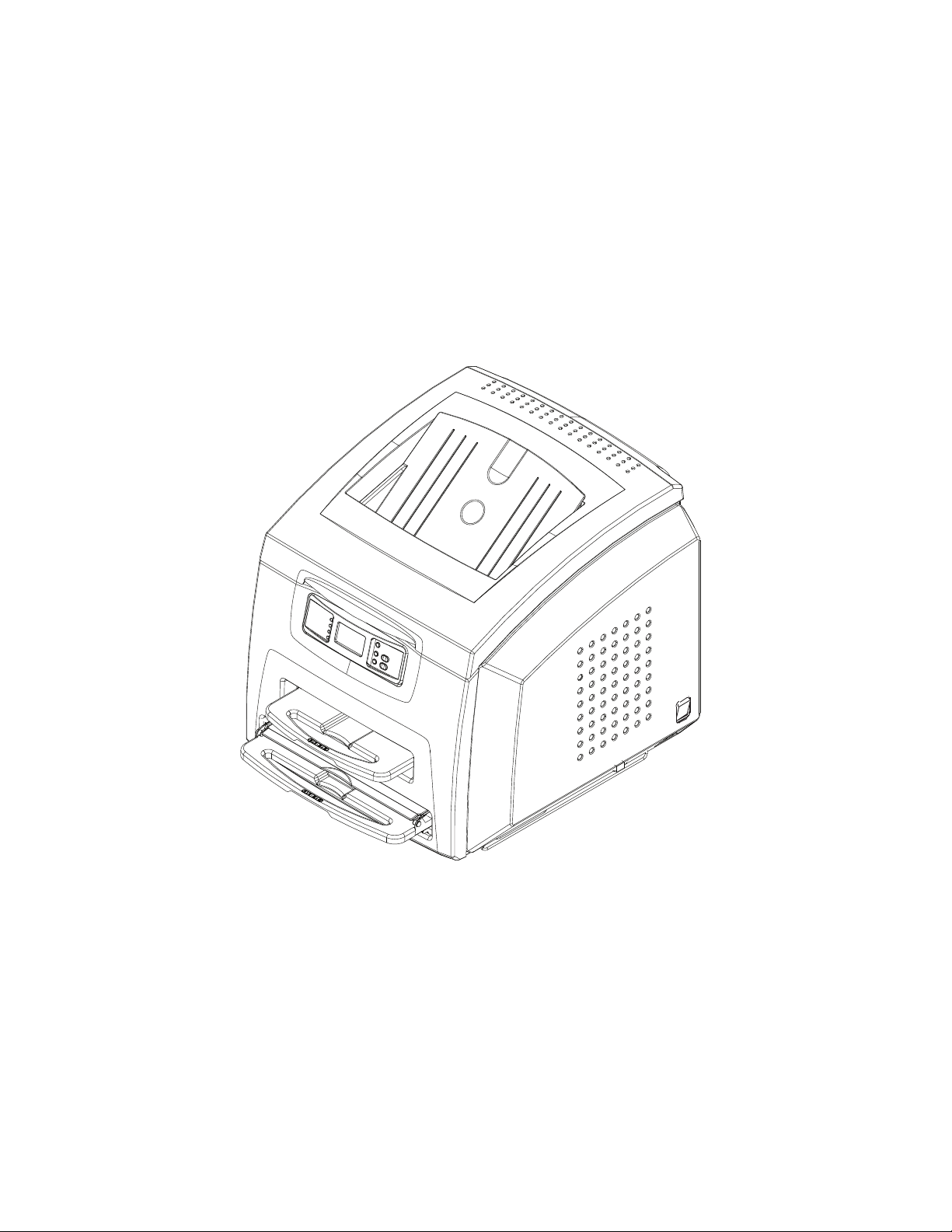
KODAK DRYVIEW 5800 Laser Imager
and
CARESTREAM DRYVIEW 5850 Laser Imager
User’s Guide

150 Verona Street
Rochester, New York 14608
© Carestream Health, Inc., 2009
DRYVIEW is a trademark of Carestream Health, Inc.
The Kodak trademark and trade dress are used under license
from Kodak.
Pub No. 2G0733
Rev. C

Table of Contents
1 Overview - - - - - - - - - - - - - - - - - - - - - - - - - - - - - - - - - - - - - - - - - - - - - - - - - - - - - - - - - 1-1
DRYVIEW 5800 and 5850 Laser Imagers - - - - - - - - - - - - - - - - - - - - - - - - - - - - - - - - - - - - - - - - - 1-1
How the Laser Imagers Work - - - - - - - - - - - - - - - - - - - - - - - - - - - - - - - - - - - - - - - - - - - - - - - - - 1-2
System Components - - - - - - - - - - - - - - - - - - - - - - - - - - - - - - - - - - - - - - - - - - - - - - - - - - - - - - - 1-3
Print Sequence - - - - - - - - - - - - - - - - - - - - - - - - - - - - - - - - - - - - - - - - - - - - - - - - - - - - - - - - - - - 1-4
Automatic Image Quality Control - - - - - - - - - - - - - - - - - - - - - - - - - - - - - - - - - - - - - - - - - - - - - - 1-5
Agency Compliance - - - - - - - - - - - - - - - - - - - - - - - - - - - - - - - - - - - - - - - - - - - - - - - - - - - - - - - - 1-5
User Guide Conventions - - - - - - - - - - - - - - - - - - - - - - - - - - - - - - - - - - - - - - - - - - - - - - - - - - - - - 1-5
2 Using and Maintaining the Imager - - - - - - - - - - - - - - - - - - - - - - - - - - - - - - - - - - - - - - - 2-1
Operator Control of the Imager - - - - - - - - - - - - - - - - - - - - - - - - - - - - - - - - - - - - - - - - - - - - - - - - 2-1
Turning Imager Power ON and OFF - - - - - - - - - - - - - - - - - - - - - - - - - - - - - - - - - - - - - - - - - - - - - 2-1
Local Panel and Display Screen - - - - - - - - - - - - - - - - - - - - - - - - - - - - - - - - - - - - - - - - - - - - - - - - 2-2
Local Panel Layout - - - - - - - - - - - - - - - - - - - - - - - - - - - - - - - - - - - - - - - - - - - - - - - - - - - - - - 2-2
Display Screen Icons - - - - - - - - - - - - - - - - - - - - - - - - - - - - - - - - - - - - - - - - - - - - - - - - - - - - - 2-3
Web Portal - - - - - - - - - - - - - - - - - - - - - - - - - - - - - - - - - - - - - - - - - - - - - - - - - - - - - - - - - - - - - - 2-5
Levels of User Access - - - - - - - - - - - - - - - - - - - - - - - - - - - - - - - - - - - - - - - - - - - - - - - - - - - - 2-5
Accessing the Web Portal - - - - - - - - - - - - - - - - - - - - - - - - - - - - - - - - - - - - - - - - - - - - - - - - - - 2-6
Operations - - - - - - - - - - - - - - - - - - - - - - - - - - - - - - - - - - - - - - - - - - - - - - - - - - - - - - - - - - - - - - 2-8
Unloading and loading the Film Tray - - - - - - - - - - - - - - - - - - - - - - - - - - - - - - - - - - - - - - - - - - 2-8
Inserting the Film Saver and Removing the Film Tray - - - - - - - - - - - - - - - - - - - - - - - - - - - - - 2-11
Removing Print Jobs From the Unprintable Jobs Queue - - - - - - - - - - - - - - - - - - - - - - - - - - - - 2-11
Calibration Prints - - - - - - - - - - - - - - - - - - - - - - - - - - - - - - - - - - - - - - - - - - - - - - - - - - - - - - 2-12
Running a Calibration Print - - - - - - - - - - - - - - - - - - - - - - - - - - - - - - - - - - - - - - - - - - - - - - - 2-12
Calibration Failure - - - - - - - - - - - - - - - - - - - - - - - - - - - - - - - - - - - - - - - - - - - - - - - - - - - - - 2-12
Working with Quality Test Prints - - - - - - - - - - - - - - - - - - - - - - - - - - - - - - - - - - - - - - - - - - - 2-13
Requesting a Test Print at the Imager - - - - - - - - - - - - - - - - - - - - - - - - - - - - - - - - - - - - - - - 2-13
Requesting a Test Print at the Web Portal - - - - - - - - - - - - - - - - - - - - - - - - - - - - - - - - - - - - 2-13
Operator Maintenance - - - - - - - - - - - - - - - - - - - - - - - - - - - - - - - - - - - - - - - - - - - - - - - - - - - - - 2-14
Changing the Charcoal Filter - - - - - - - - - - - - - - - - - - - - - - - - - - - - - - - - - - - - - - - - - - - - - - 2-14
3 Troubleshooting - - - - - - - - - - - - - - - - - - - - - - - - - - - - - - - - - - - - - - - - - - - - - - - - - - - - 3-1
Error and Alarm Indications - - - - - - - - - - - - - - - - - - - - - - - - - - - - - - - - - - - - - - - - - - - - - - - - - - 3-1
DICOM Printer Status Messages - - - - - - - - - - - - - - - - - - - - - - - - - - - - - - - - - - - - - - - - - - - - - - - 3-1
Printer Status Messages - - - - - - - - - - - - - - - - - - - - - - - - - - - - - - - - - - - - - - - - - - - - - - - - - - - - - 3-2
Film Supply Status Messages - - - - - - - - - - - - - - - - - - - - - - - - - - - - - - - - - - - - - - - - - - - - - - - - - 3-3
Job Manager Status Messages - - - - - - - - - - - - - - - - - - - - - - - - - - - - - - - - - - - - - - - - - - - - - - - - - 3-5
Condition Codes - - - - - - - - - - - - - - - - - - - - - - - - - - - - - - - - - - - - - - - - - - - - - - - - - - - - - - - - - - 3-6
Clearing Film Jams - - - - - - - - - - - - - - - - - - - - - - - - - - - - - - - - - - - - - - - - - - - - - - - - - - - - - - - 3-13
Film Jam - Code 2x-116 - - - - - - - - - - - - - - - - - - - - - - - - - - - - - - - - - - - - - - - - - - - - - - - - - - 3-14
Film Jam - Code 2x126 - - - - - - - - - - - - - - - - - - - - - - - - - - - - - - - - - - - - - - - - - - - - - - - - - - 3-17
Film Jam - Code 26325 - - - - - - - - - - - - - - - - - - - - - - - - - - - - - - - - - - - - - - - - - - - - - - - - - - 3-19
Film Jam - Codes 26326 or 26543 - - - - - - - - - - - - - - - - - - - - - - - - - - - - - - - - - - - - - - - - - - - 3-19
Film Jam - Code 26544 - - - - - - - - - - - - - - - - - - - - - - - - - - - - - - - - - - - - - - - - - - - - - - - - - - 3-21
Calling for Support - - - - - - - - - - - - - - - - - - - - - - - - - - - - - - - - - - - - - - - - - - - - - - - - - - - - - - - 3-22
May 6, 2009 2G0733 i

4 Film Technical Information - - - - - - - - - - - - - - - - - - - - - - - - - - - - - - - - - - - - - - - - - - - - 4-1
General Description - - - - - - - - - - - - - - - - - - - - - - - - - - - - - - - - - - - - - - - - - - - - - - - - - - - - - - - - 4-1
Spectral Sensitivity - - - - - - - - - - - - - - - - - - - - - - - - - - - - - - - - - - - - - - - - - - - - - - - - - - - - - - 4-1
Image Quality - - - - - - - - - - - - - - - - - - - - - - - - - - - - - - - - - - - - - - - - - - - - - - - - - - - - - - - - - 4-1
Environmental Impact - - - - - - - - - - - - - - - - - - - - - - - - - - - - - - - - - - - - - - - - - - - - - - - - - - - - 4-2
Storing and Handling Undeveloped Film - - - - - - - - - - - - - - - - - - - - - - - - - - - - - - - - - - - - - - - 4-2
Handling Developed Film - - - - - - - - - - - - - - - - - - - - - - - - - - - - - - - - - - - - - - - - - - - - - - - - - 4-2
Archiving Developed Film - - - - - - - - - - - - - - - - - - - - - - - - - - - - - - - - - - - - - - - - - - - - - - - - - 4-3
Exposing to Moisture - - - - - - - - - - - - - - - - - - - - - - - - - - - - - - - - - - - - - - - - - - - - - - - - - - - - 4-3
Dissipating Odor - - - - - - - - - - - - - - - - - - - - - - - - - - - - - - - - - - - - - - - - - - - - - - - - - - - - - - - 4-3
Dissipating Heat - - - - - - - - - - - - - - - - - - - - - - - - - - - - - - - - - - - - - - - - - - - - - - - - - - - - - - - - 4-3
Recycling Film - - - - - - - - - - - - - - - - - - - - - - - - - - - - - - - - - - - - - - - - - - - - - - - - - - - - - - - - - 4-3
5 Specifications - - - - - - - - - - - - - - - - - - - - - - - - - - - - - - - - - - - - - - - - - - - - - - - - - - - - - - 5-1
Location - - - - - - - - - - - - - - - - - - - - - - - - - - - - - - - - - - - - - - - - - - - - - - - - - - - - - - - - - - - - - - - 5-1
Equipment Specifications - - - - - - - - - - - - - - - - - - - - - - - - - - - - - - - - - - - - - - - - - - - - - - - - - 5-1
Operating Space Requirements - - - - - - - - - - - - - - - - - - - - - - - - - - - - - - - - - - - - - - - - - - - - - - 5-1
Other Location Considerations - - - - - - - - - - - - - - - - - - - - - - - - - - - - - - - - - - - - - - - - - - - - - - 5-2
Environmental Requirements - - - - - - - - - - - - - - - - - - - - - - - - - - - - - - - - - - - - - - - - - - - - - - - - - 5-3
Temperature - - - - - - - - - - - - - - - - - - - - - - - - - - - - - - - - - - - - - - - - - - - - - - - - - - - - - - - - - - 5-3
Relative Humidity - - - - - - - - - - - - - - - - - - - - - - - - - - - - - - - - - - - - - - - - - - - - - - - - - - - - - - 5-3
Altitude - - - - - - - - - - - - - - - - - - - - - - - - - - - - - - - - - - - - - - - - - - - - - - - - - - - - - - - - - - - - - - 5-3
Surface Condition - - - - - - - - - - - - - - - - - - - - - - - - - - - - - - - - - - - - - - - - - - - - - - - - - - - - - - - 5-3
Environmental Effects - - - - - - - - - - - - - - - - - - - - - - - - - - - - - - - - - - - - - - - - - - - - - - - - - - - - - - 5-3
Laser Specifications - - - - - - - - - - - - - - - - - - - - - - - - - - - - - - - - - - - - - - - - - - - - - - - - - - - - - - - 5-3
Power Requirements - - - - - - - - - - - - - - - - - - - - - - - - - - - - - - - - - - - - - - - - - - - - - - - - - - - - - - - 5-4
Network Requirements - - - - - - - - - - - - - - - - - - - - - - - - - - - - - - - - - - - - - - - - - - - - - - - - - - - - - 5-4
Film - - - - - - - - - - - - - - - - - - - - - - - - - - - - - - - - - - - - - - - - - - - - - - - - - - - - - - - - - - - - - - - - - - 5-4
Film Types - - - - - - - - - - - - - - - - - - - - - - - - - - - - - - - - - - - - - - - - - - - - - - - - - - - - - - - - - - - 5-4
Film Sizes - - - - - - - - - - - - - - - - - - - - - - - - - - - - - - - - - - - - - - - - - - - - - - - - - - - - - - - - - - - - 5-5
Film Storage - - - - - - - - - - - - - - - - - - - - - - - - - - - - - - - - - - - - - - - - - - - - - - - - - - - - - - - - - - 5-5
Glossary - - - - - - - - - - - - - - - - - - - - - - - - - - - - - - - - - - - - - - - - - - - - - - - - - - - - - - - - - - - G-1
Appendix A: Warranty and Limitation of Liability - - - - - - - - - - - - - - - - - - - - - - - - - - - - A-1
Important Notice to Purchaser - - - - - - - - - - - - - - - - - - - - - - - - - - - - - - - - - - - - - - - - - - - - - - - - - A-1
End User License Agreement (EULA) - - - - - - - - - - - - - - - - - - - - - - - - - - - - - - - - - - - - - - - - - - - A-2
Carestream Health, Inc. Software End User License Agreement - - - - - - - - - - - - - - - - - - - - - - - - A-2
End-User License Agreement for Microsoft Desktop Operating Systems - - - - - - - - - - - - - - - - - - A-4
ii 2G0733 May 6, 2009

1 Overview
DRYVIEW 5800 and 5850 Laser Imagers
The 5800 and 5850 Laser Imagers are continuous-tone laser imagers
with an internal photothermographic film processor. Heat, rather than
photo chemicals, is used to develop the film. The Laser Imagers receive
digital images from medical image source devices (modalities) over a
network. The format that the Imager accepts is DICOM.
The Laser Imagers print images on KODAK DRYVIEW Laser Imaging
Film. Each film package contains 100 sheets of film. The Imagers can
accept any type and size of film as described in Chapter 5 of this
manual.
Intended Use The KODAK DRYVIEW 5800 Laser Imager provides high quality hard
copy film output from digital imaging source modalities for use in
medical imaging diagnosis and referral. Electronic image information
signals are managed and transformed optically to expose KODAK
DRYVIEW media. The system is intended for use with a variety of
digital modalities including, but not limited to, CT (Computerized
Tomography), MR (Magnetic Resonance) and CR (Computed
Radiology) for diagnostic use by medical radiologists and
communications to referring physicians and their patients.
The CARESTREAM DRYVIEW 5850 Laser Imager is intended to
provide high-resolution hard copy images from digital imaging source
output signals. The device is intended for use with KODAK DRYVIEW
media including DVM (DRYVIEW Mammography Films). The imager
will interface with a variety of digital modalities, including, but not
limited to, CR (Computed Radiology), DR (Digital Radiology), CT
(Computerized Tomography), MRI (Magnetic Resonance Imaging), and
FFDM (Full Field Digital Mammography). Image resizing is used to
preserve true geometric size images. The images are to be used for
medical diagnosis and referral to physicians and their patients.
Note: The DRYVIEW 5850 automatically performs interpolation
(image resizing) to ensure a true geometric size image match
between the modality detector and the printed film. For
example, for those modalities where the detector pixel size is
less than 50 microns, the DRYVIEW 5850 automatically
resizes the detector image matrix downward to ensure true
geometric size images on the printed film. For those modalities
where the detector pixel size is greater than 50 microns, the
DRYVIEW 5850 automatically resizes the detector image
matrix upward to ensure true geometric size images on the
printed film.
May 6, 2009 2G0733 1-1
Overview
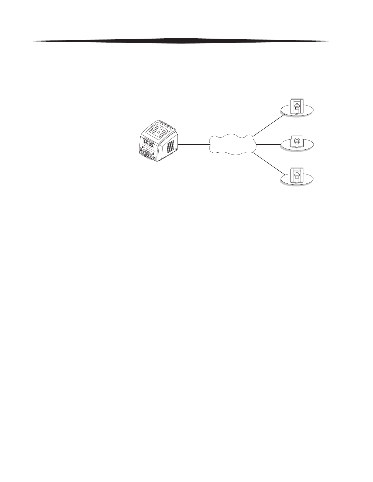
5800 or 5850 Laser Imager
Network
Modality
Modality
Modality
How the Laser Imagers Work
The Imagers are network printers connected on a network along with one or
more medical imaging devices. They print images sent over the network
from medical imaging devices or workstations sending images concurrently.
The Imagers have hard-disk storage for a large number of digital images. As
images arrive, they are stored on the hard disk and placed in a print queue
(sequenced for printing) based on time of receipt and priority. Because the
Imagers can store images, they can continue to accept incoming print jobs
even when the film cartridge is empty or the Imager is temporarily unable to
print. Images that require a different film size or film type than is currently
in the Imager are placed in a separate “waiting for media” queue and a code
on the Local Panel reminds the operator to change film.
During normal operation, the Imager requires very little operator attention.
The Imager prints automatically in response to print requests from the
associated image devices. Information sent along with print requests, such
as film size, density and priority, control the print operations. Main operator
responsibilities include loading film and monitoring for malfunctions.
1-2 2G0733 May 6, 2009

System Components
1
2
3
4
5
Overview
1 Film trays. Your Imager is configured with two film trays. Each
film tray holds a different size of DRYVIEW Laser Imaging
Film. Both film trays must be installed in order for the Imager to
operate.
2 Film feed transport. The film feed transport orients and centers
the film while moving the film from the film tray to the imaging
portion of the Imager.
3 Film imaging. The optics module writes the image onto the film
while the film is moved through the exposure transport area.
4 Film processor. The film processor uses heat to develop the
image written onto the film by the laser in the optics module.
5 Local panel. The local panel contains the display screen.
May 6, 2009 2G0733 1-3

Overview
1
2
3
4
5
Print Sequence
When the Imager receives a print request, it determines the requested film
size and type and then it selects the appropriate film tray.
Each time the Imager receives a print request, the following print sequence
occurs:
1. Suction cups in the pickup area lift a single sheet of film out of the
tray and feed the film into the transport rollers.
2. The transport rollers move the film up into the registration transport
area, where film registration takes place.
3. As the film moves through the exposure transport, the optics module
writes the image onto the film, then moves the film into the film
processor.
1-4 2G0733 May 6, 2009
4. As the film passes over the processor drum, the heat generated by the
drum develops the film.
5. The film transport rollers move the exposed film to the exit area.

Automatic Image Quality Control
CAUTION:
LASER WARNING:
An internal densitometer is a key element in the Automatic Image Quality
Control (AIQC) process. The densitometer enables the Imager to
automatically adjust image processing parameters to produce the best image.
The Imager adjusts these parameters each time it prints a calibration film.
A calibration film is printed when:
• The film tray is inserted in the Imager with film of a new lot number.
• A calibration film is requested from the local panel or web portal.
• A film tray is inserted into the Imager for which a current calibration
is not stored.
Agency Compliance
See the Safety Manual for the KODAK DRYVIEW 5800 Laser Imager and
CARESTREAM DRYVIEW 5850 Laser Imager, 2G0734.
Overview
User Guide Conventions
The following special messages emphasize information or indicate potential
risks to personnel or equipment.
NOTE: Notes provide additional information, such as expanded
explanations, hints, or reminders.
IMPORTANT: Important notes highlight critical policy information that
Cautions point out procedures that you must follow precisely to
avoid damage to the system or any of its components, loss of data,
or corruption of files in software applications.
DANGER: Danger identifies procedures that you must follow
Laser warnings warn personnel that access to laser radiation is
possible and all personnel must avoid direct exposure to the beam.
affects how you use this guide and this product.
precisely to avoid injury to yourself or others.
May 6, 2009 2G0733 1-5

2 Using and Maintaining the
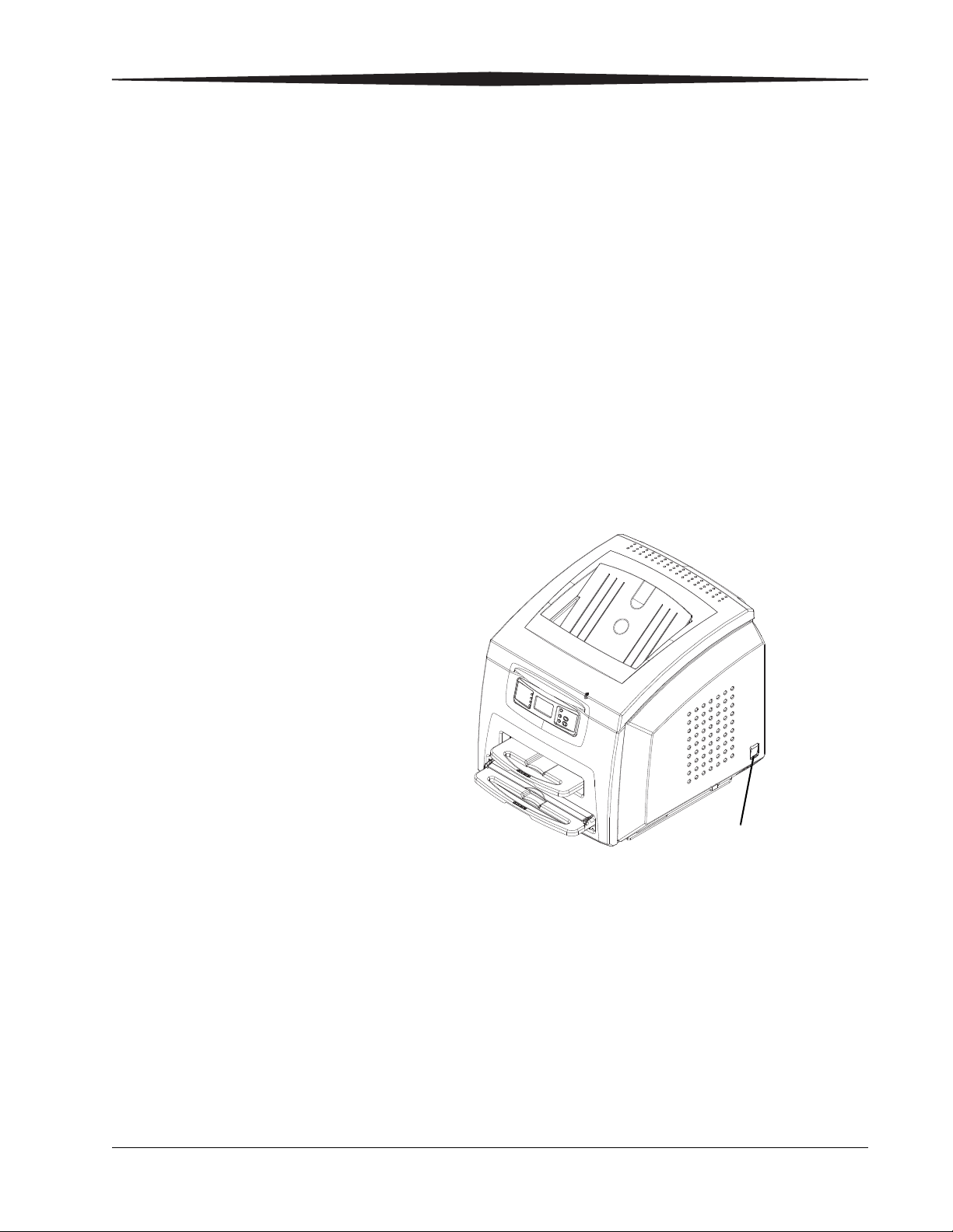
Power switch
Imager
Operator Control of the Imager
During normal operation, the Imager receives and automatically prints
images sent by modalities over a network. Very little operator control is
required. The main responsibilities of the operator are described in the
following section, along with overview information about using the
Imager.
Turning Imager Power ON and OFF
There is a power switch located at the back right of the Imager.
In the event of a power loss, the Imager shuts down. Films in process
will not be completed and will remain where they are located in the
Imager.
The Imager will restart after power is restored. After self-test, the
Imager clears any films in process and automatically reprints any films
that were in process when power was interrupted.
May 6, 2009 2G0733 2-1
Using and Maintaining the Imager
1
2
3
4
567
8
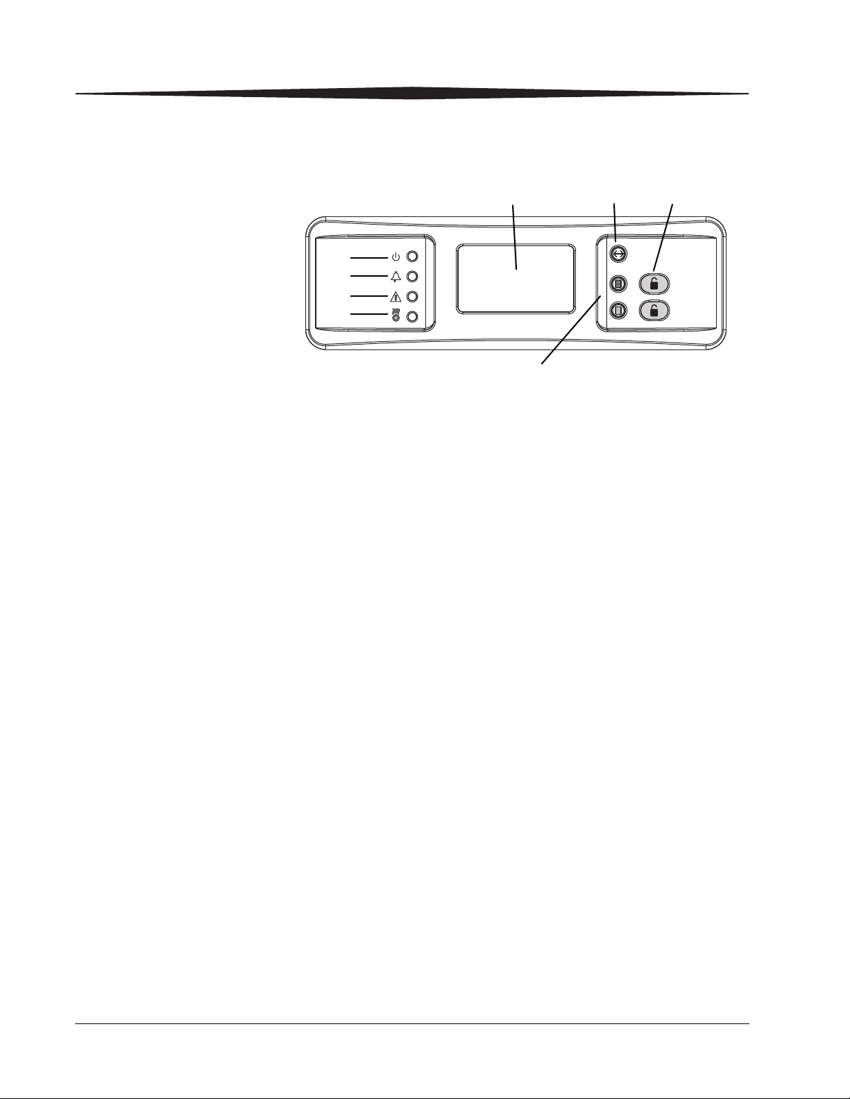
Local Panel and Display Screen
Local Panel / Display Screen
1 Ready LED. This LED, when steady on indicates that the Imager is ready for printing.
When flashing, the Imager is processing and printing films. When unlit, the Imager is not
ready to print.
2 Error LED. When lit, this LED indicates that the Imager has an error. An error code
appears on the display screen.
3 Attention LED. When lit, this LED indicates a condition that requires attention, such as
"out of film". The Imager can still process and print films from unaffected film trays.
4 Warming LED. When lit, this LED indicates that the Imager is warming up. A timer is
also shown on the display screen indicating the amount of time, in minutes, before the
Imager reaches operating temperature.
5 Display screen. Displays codes and icons that indicate the status and operating condition
of the Imager.
6 Menu Selection Button. In Menu Selection Mode, you can work with menus on the
Display Screen, and the functionality of buttons on the right side of the Local Panel
change. To enter Menu Selection Mode, press and hold the Menu Selection Button (#6
on the graphic above) for 5 seconds. The following screens are available:
• Test Print screen: Select a test print (only SMPTE is available for 5800 Imager.
Other prints are available for mammography quality control for the 5850 Imager.)
• Maintenance Reset screen: Reset maintenance items such as reset print counts,
jobs to delete, etc.).
7 Unlock buttons. Used to unlock the film trays. Note that the trays will not unlock unless
a film saver is installed in trays that have film.
{
Note: These buttons are used to select or cancel when in Menu Selection Mode. See
the Icons table on page 2-4.
8 Calibration buttons. Initiate a manual film calibration for upper and lower film trays.
NOTE: These buttons are used to move up or down in a menu when in Menu
2-2 2G0733 May 6, 2009
Selection Mode. See the Icons table on page 2-4.
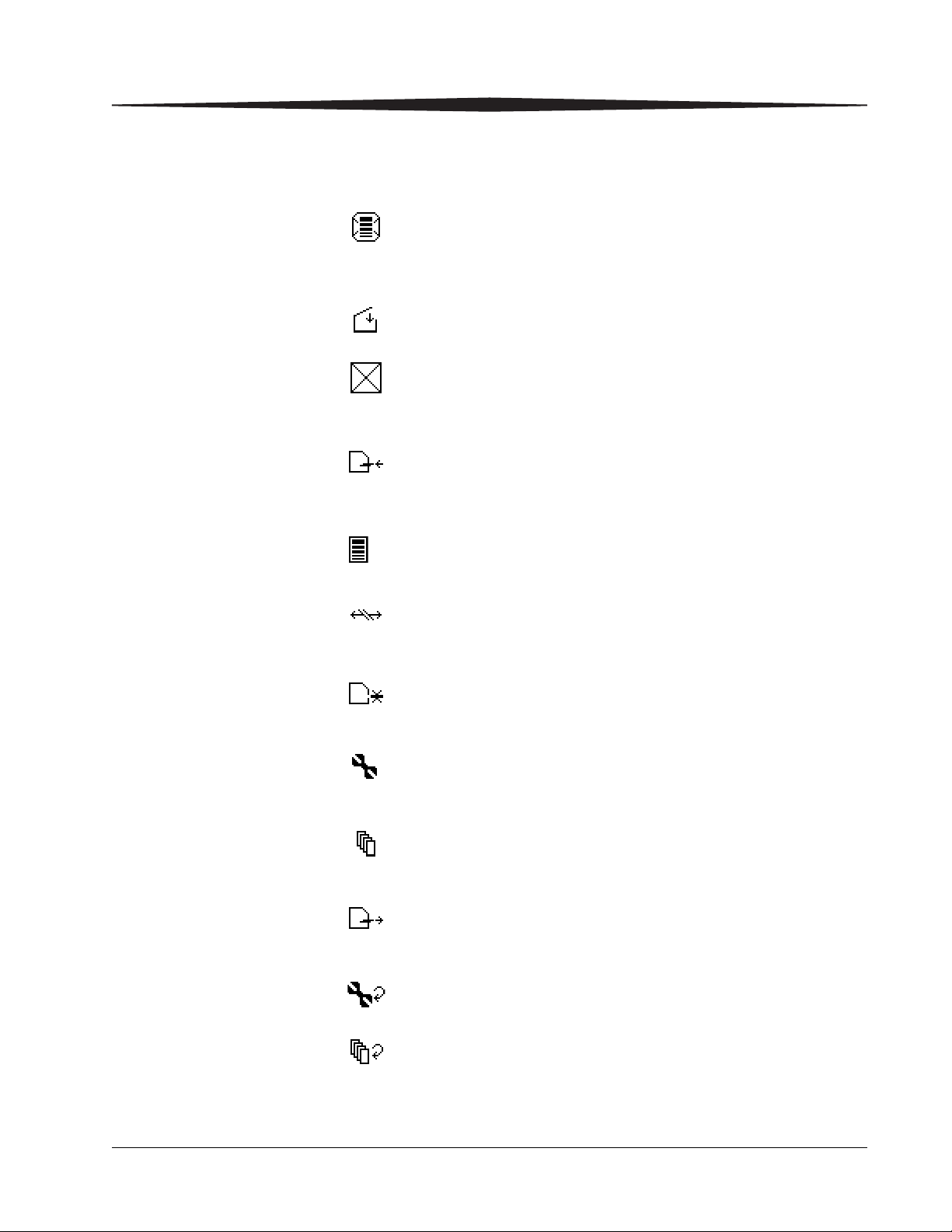
Display Screen Icons
Using and Maintaining the Imager
Icon Description
This icon indicates that film calibration is required. The Imager is
unable to print jobs from this tray until a successful calibration
occurs.
This icon indicates that a door is open on the Imager.
This icon indicates an error with the film tray. An error code will
also be shown on the display screen. The film tray cannot be used
until the error is corrected.
This icon indicates that you should insert the film saver into the
film tray.
This icon appears when the film fails calibration and indicates
that the Imager has been placed in manual mode.
This icon indicates that the DICOM network connection to the
Imager is offline.
This icon indicates that a film tray is not installed. Both film trays
must be installed in order for the Imager to operate.
This icon indicates that preventive maintenance is due.
This icon indicates that one or more jobs are present in the
Unprintable Job Queue.
This icon indicates that the film saver must be removed from the
film tray.
This icon indicates that a reset of the print counts to preventive
maintenance is due.
This icon indicates there are prints in the queue that are waiting to
be deleted.
May 6, 2009 2G0733 2-3

Using and Maintaining the Imager
Icons in Menu Selection Mode
Icon Description
This icon indicates that a user-initiated system restart is in
process.
This icon indicates that the Imager has been placed in service
mode.
This icon indicates that the Imager is warming up. The amount of
time remaining until the Imager reaches operating temperature is
also shown on the display screen.
The following icons appear on the Display Screen when you are
in Menu Selection Mode. These icons represent the changed
functionality of the buttons on the right side of the Local Panel.
While in Menu Selection Mode, press the button (#6 in the
graphic on page 2-2) to display the Test Print or Maintenance
Reset screen.
These icons indicate that the buttons shown by #8 in the graphic
on page 2-2 have changed functionality. Rather than being used
as Calibration buttons, you now use these buttons to move up or
down in the menu on the Display Screen.
This icon indicates that the button shown by the upper #7 in the
graphic on page 2-2 is no longer an Unlock button. Instead, use
the button to select the currently highlighted menu item.
This icon indicates that the button shown by the lower #7 in the
graphic on page 2-2 is no longer an Unlock button. Instead, use
the button to cancel the selection.
2-4 2G0733 May 6, 2009

Web Portal
Using and Maintaining the Imager
The Web Portal is your interface to additional functions on the Imager. In
the Web Portal, you can view and manage the Imager's connections over the
network, configure features, view and correct error messages and general
status, etc.
After you have accessed the Web Portal, you can check the status of the
Imager and check the media and status of the film trays.
With a user account, you can log on to the Web Portal to perform more
advanced functions such as:
• Setting up and working with network configuration for the imager
and connected image sources.
• Retrieving logs, statistics, and system status.
• Performing diagnostic utilities, including backup and restore.
Levels of User Access
IMPORTANT: For information about creating user accounts, refer to the
Web Portal Help system.
There are four levels of user access to the Imager.
Level 1: Operator - Activities include printing, clearing of some errors, and
removing film jams and deleting jobs. A password is not required
for this level of access.
Level 2: Key Operator - Activities include printing, clearing of some
errors, removing film jams, performing minor setup, and deleting
jobs. Access to Level 2 requires a Level 2 ID and password.
Level 3: Local Service - Local Service providers are Carestream Health
trained and certified self-maintenance customers. Level 3 First Call
Service provides access to all Level 1 and 2 features and functions.
In addition, First Call activities include preventive maintenance with
the ability to reset some imaging parameters. Access to Level 3
requires a Level 3 ID and password.
Level 4: Full Service - Full Service providers are Carestream Health Field
Engineers, Technical Support staff, and certified service partners.
Level 4 Full Service requires licensing for a specified period. Full
Service providers have access to all Level 1, 2, and 3 service
features. The providers can also access the laser imager through a
service computer or through a remote computer connected to the
network. Access to Level 4 requires a Service ID and password.
May 6, 2009 2G0733 2-5
Using and Maintaining the Imager
Accessing the Web Portal
To access the Web Portal you will need a desktop or laptop computer that is
connected to the network.
1. On a desktop or laptop computer, start WINDOWS Internet Explorer.
2. In the address field, type: http://<IP address>
Note: <IP address> is the IP address of the Imager.
3. Click Go.
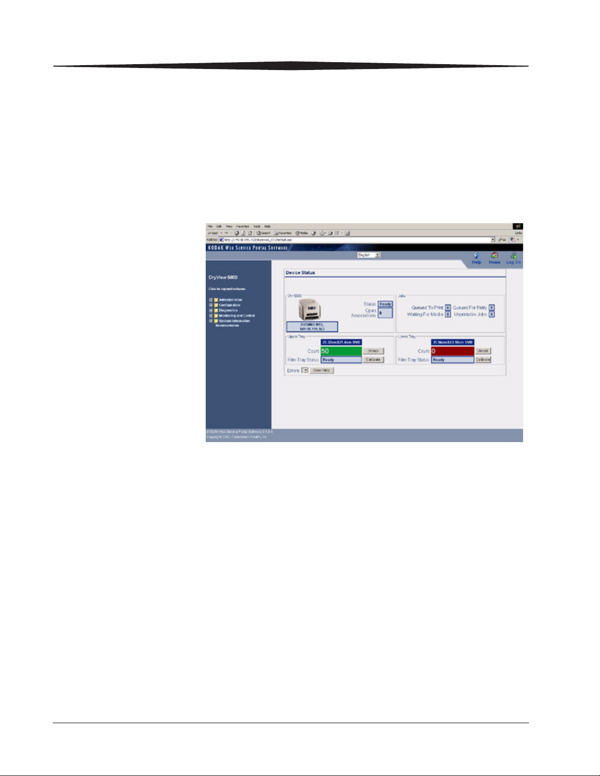
The main window for the Web Portal appears.
The center panel displays the screens where you view and perform
tasks. On-line help is available by selecting “Documentation” from
the left panel. The left panel displays links to all other screens.
2-6 2G0733 May 6, 2009

Using and Maintaining the Imager
To log on to the Web Portal as a Level 2 or Level 3 user, do the following.
1. Click the Log On icon.
The following window appears.
2. Enter your User ID and password.
NOTE: The Imager comes with a default User ID and password for Level
2 and Level 3 users.
• for Level 2: User ID = KeyOperator; Password = DV5800
• for Level 3: User ID = LocalService; Password = DV5800
NOTE: The password is the same for the 5800 and 5850 Laser Imagers.
3. Click Login.
The items on the left side of the display will differ according to your
level of access.
May 6, 2009 2G0733 2-7
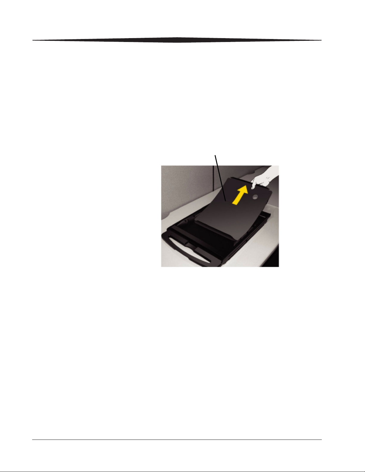
Using and Maintaining the Imager
Film insert
Operations
Unloading and loading the Film Tray
IMPORTANT: Leave the Imager powered on while loading or unloading
the film tray.
When 100 sheets of film have been used, a 0 film count appears on the
display screen.
1. Press the “unlock” button on the local panel to release the film tray.
2. Remove the film tray from the Imager.
3. Remove the old film insert from the tray and discard in a manner
suitable to local ordinances.
NOTE: Before loading a new package of film, clean any particles from the
inside surface of the film tray, including the ramp and top edge of
the tray.
2-8 2G0733 May 6, 2009
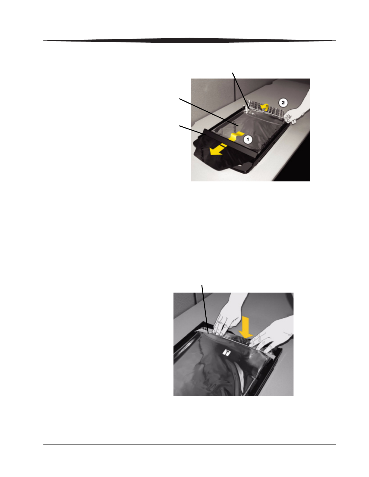
Using and Maintaining the Imager
Bag holder
Diverter
Film
package
Bag holder
4. Pull the diverter (plastic bar) and bag holder (silver bar) into the up
position.
5. Press the new film package down in the tray with the label facing up.
6. Pull the front flap of the film package forward and place it under the
diverter (1).
7. Set the back end of the film package under the bag holder (2).
8. Press down firmly using both hands so the film package sits flat
against the bottom of the tray.
9. Swing the bag holder of the film tray back in place.
May 6, 2009 2G0733 2-9
Using and Maintaining the Imager
Tear strip
Plastic bag
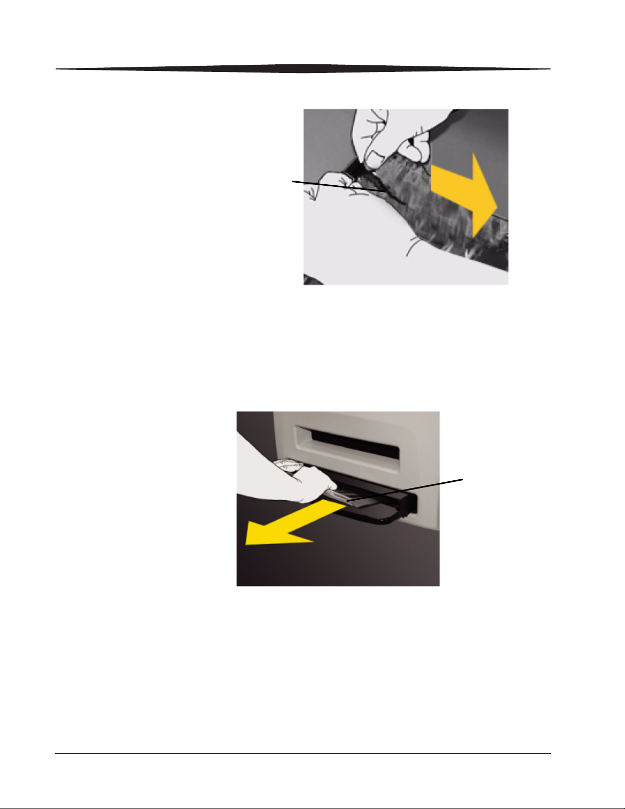
10. Remove the tear strip from the plastic bag.
11. Swing the diverter of the film tray back in place.
IMPORTANT:Do not install the Film Saver onto the film tray.
12. Slide the tray back into the Imager slot.
13. To remove the plastic bag so the Imager can access the film, pull the
plastic bag tail firmly and smoothly. The entire film bag will slide
out.
2-10 2G0733 May 6, 2009
Using and Maintaining the Imager
H221_0002BC
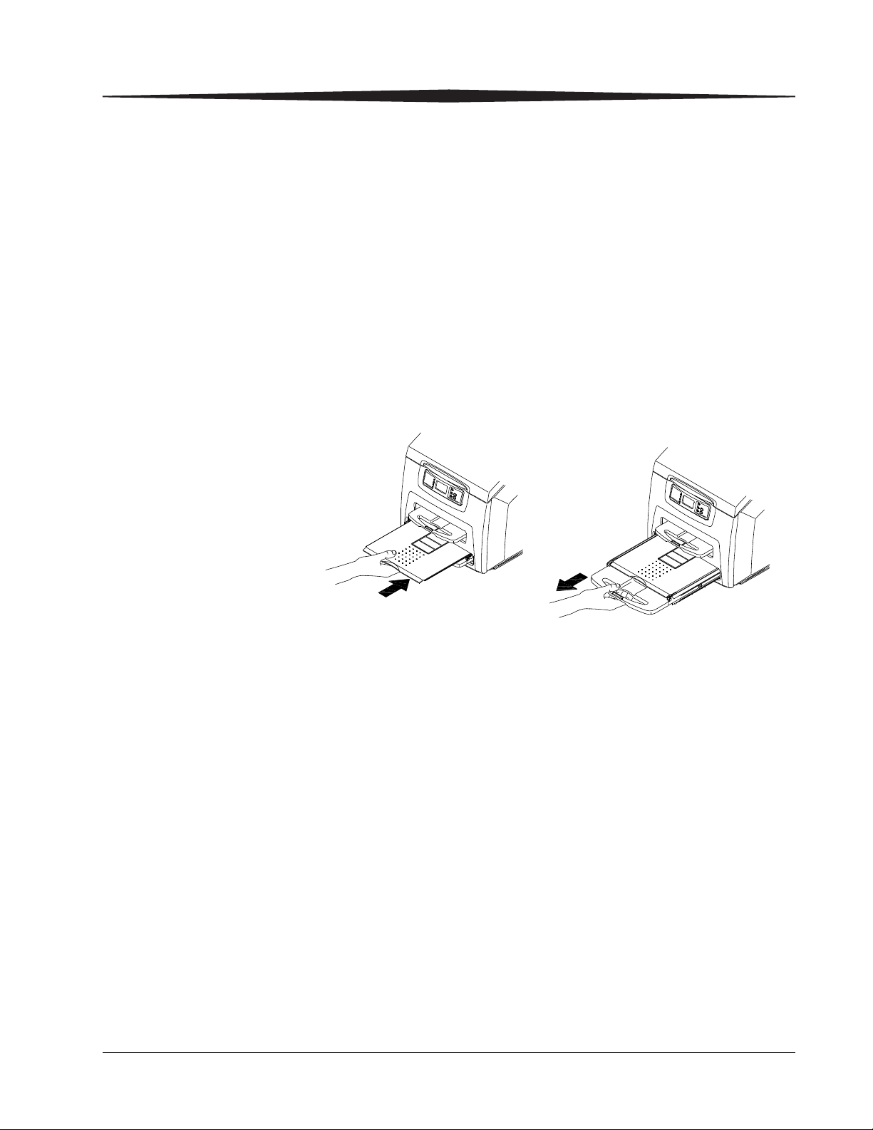
Inserting the Film Saver and Removing the Film Tray
A film saver must be inserted into a film tray before:
• the hood is opened.
• any panel on the Imager is removed.
• a film tray with film in it is removed.
1. Insert the film saver as shown below.
2. If the film tray has not been unlocked, press the "unlock" button on
the local panel.
NOTE: The film tray must be removed within 30 seconds after pressing
the "unlock" button. Otherwise, the film tray will re-lock
automatically.
3. Remove the film tray as shown below.
Removing Print Jobs From the Unprintable Jobs Queue
Inserting the Film Saver
Note: The film saver can be stored under the film tray until required.
When there are jobs in the unprintable jobs queue that can not be printed,
condition code 20703 and an icon show on the display screen. To remove
these jobs from the print queue, do the following.
1. Press and hold the Menu Selection Button for 5 seconds. Release the
button and the Test Print Menu displays.
2. Press and release the Menu Selection Button again to display the
Error Reset Menu.
3. Check that the 20703 error is highlighted on the display screen, then
press the Enter button.
The icon and condition code are cleared, and the display screen returns to
normal operation.
May 6, 2009 2G0733 2-11

Using and Maintaining the Imager
Calibration Prints Imager calibration is performed by printing a calibration print. A calibration
print has a step wedge pattern with a series of 26 stripes of increasing
optical density. The only purpose of a calibration print is to calibrate the
Imager. The Imager prints a calibration print when:
• A manual film calibration is requested.
• A film tray containing film with new sensitometric characteristics
(speed, contrast) is loaded.
• A film tray for which a current calibration is not stored is inserted into
the Imager.
You can discard all calibration prints.
Running a Calibration Print
You may occasionally have to request that the Imager print a calibration
print to calibrate the Imager. You may be asked to do this if you call for
service. You should also run a calibration print if a "Not Calibrated" status
message appears on the Web Portal Home screen, or if a calibration error
code (2x-624, 2x-631, or 2x-632) appears on the display screen.
To request a calibration print from the local panel, press the calibration
button for the applicable film tray (see “Local Panel / Display Screen”).
To request a calibration print from the Web Portal:
1. Access the Web Portal (see “Accessing the Web Portal”).
2. Click Calibrate, for the applicable film tray.
Calibration Failure Occasionally, the Imager may fail calibration and will notify the operator
with an error code on the display screen and a code and message on the Web
Portal. The most common cause is a film-related problem. Depending on the
cause, the Imager may be able to continue operating, but would display the
“manual mode” icon.
2-12 2G0733 May 6, 2009
Using and Maintaining the Imager
Working with Quality Test Prints
Requesting a Test Print at the Imager
Requesting a Test Print at the Web Portal
The Imager can print an internally generated density test print with a
SMPTE pattern. Density test prints can be used as a quality assurance tool to
verify the uniformity of films printed by the Imager. The 5850 Laser Imager
provides additional test prints for mammography quality control.
You can request a test print at the Imager or from the Web Portal.
1. At the Imager, press the Setup button for approximately 5 seconds.
The Test Print menu displays.
2. Select the desired test print, and press the Enter button to initiate the
test print.
3. Select Cancel to exit from the Test Print menu.
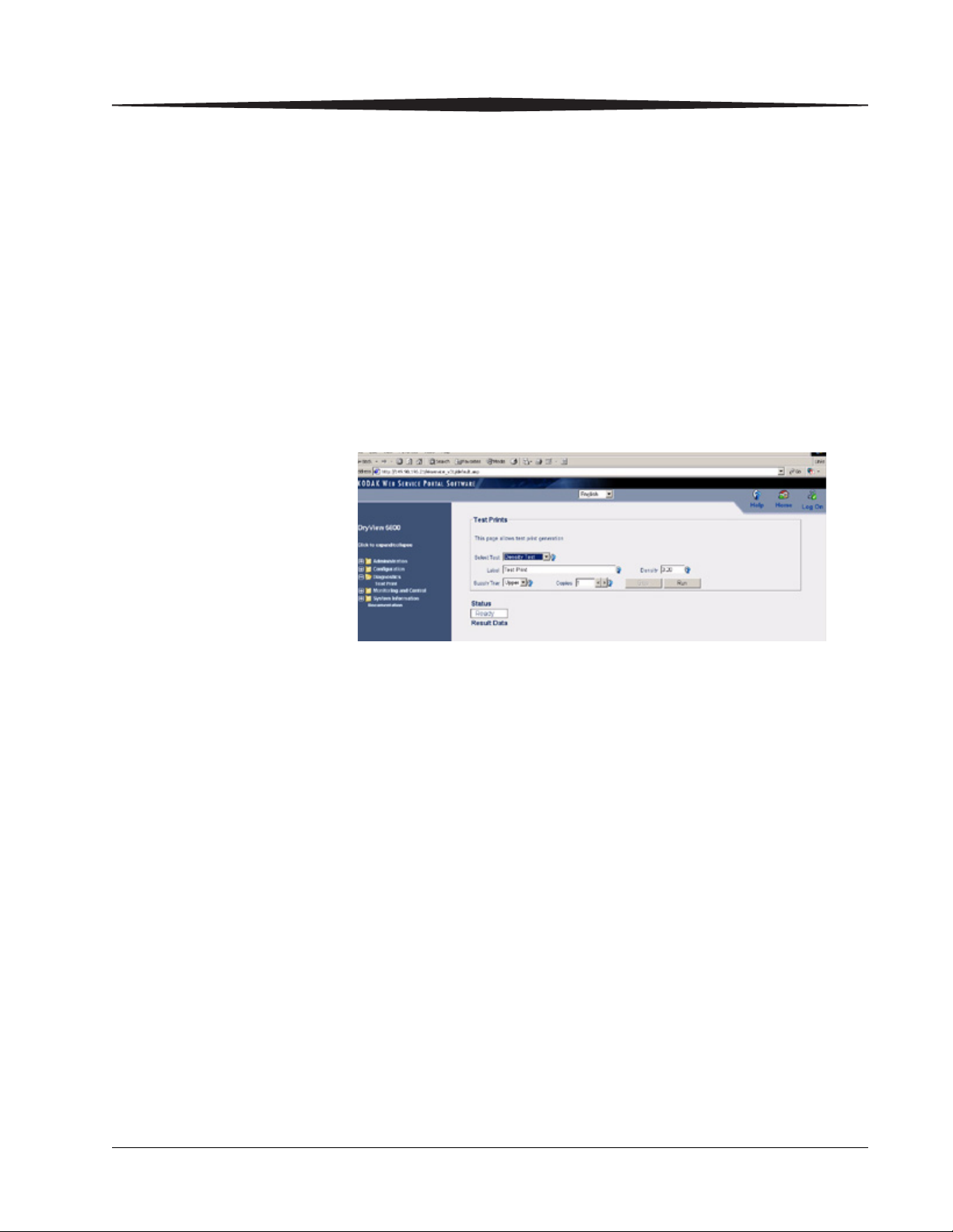
1. Access the Web Portal (see “Accessing the Web Portal”).
2. Select Diagnostics>Test Print.
3. For “Select Test,” use the drop-down menu to select the desired test.
For example, for the SMPTE pattern, select Density Test.
4. Enter an optional label to be printed on the test film.
5. Enter the desired density (0.1 to 3.2).
6. Use the drop-down menu to select the film tray.
7. Select the number of copies to be printed.
8. Click Run.
May 6, 2009 2G0733 2-13
Using and Maintaining the Imager
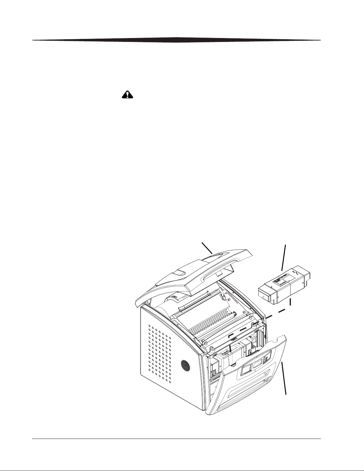
Hood
Front panel
Charcoal filter
Operator Maintenance
Changing the Charcoal Filter
In the U.S., exhausted charcoal filters are considered to be
non-hazardous waste according to the US Environmental
Protection Agency Resource Conservation Recovery Act (RCRA).
Municipality owned and licensed solid waste management facilities
are an appropriate disposal option. Contact your local or state
solid waste authorities to determine if additional disposal
requirements apply. In other regions, contact local or regional
solid waste authorities for proper disposal guidance.
The preventive maintenance filter must be changed every 7,500 films. When
it is time to replace the filter, condition code 20449 and an icon show on the
display screen.
1. Remove the film trays see (“Inserting the Film Saver and Removing
the Film Tray”).
2. Turn the Imager OFF.
2-14 2G0733 May 6, 2009
Loading...