


 Loading...
|
|
{InstallationInstructs}{Production}{Health Group}{ExternalAndInternal} |
Publication No. II4366-1 |
|
15DEC06 |
|
Supersedes II4366-1 |
|
23NOV04 |
Confidential |
|
Restricted |
|
Information |
|
|
INSTALLATION INSTRUCTIONS |
|
for the |
|
Kodak DirectView CR 500 SYSTEM |
Service Code: 4366
 Important
Qualified service personnel must install this equipment.
H195_0016BC
© EASTMAN KODAK COMPANY, 2006 |
HEALTH GROUP |

INSTALLATION INSTRUCTIONS
15DEC06 II4366-1 Page
2 of 91
PLEASE NOTE The information contained herein is based on the experience and knowledge relating to the subject matter gained by Eastman Kodak Company prior to publication.
No patent license is granted by this information.
Eastman Kodak Company reserves the right to change this information without notice, and makes no warranty, express or implied, with respect to this information. Kodak shall not be liable for any loss or damage, including consequential or special damages, resulting from any use of this information, even if loss or damage is caused by Kodak’s negligence or other fault.
This equipment includes parts and assemblies sensitive to damage from electrostatic |
|
discharge. Use caution to prevent damage during all service procedures. |
|
Table of Contents |
|
Description |
Page |
Safety . . . . . . . . . . . . . . . . . . . . . . . . . . . . . . . . . . . . . . . . . . . . . . . . . . . . . . . . . . . . . . . . |
4 |
Installation . . . . . . . . . . . . . . . . . . . . . . . . . . . . . . . . . . . . . . . . . . . . . . . . . . . . . . . . . . . . |
7 |
Connecting the UNINTERRUPTED POWER SUPPLY (UPS). . . . . . . . . . . . |
7 |
Removing the Packing Material. . . . . . . . . . . . . . . . . . . . . . . . . . . . . . . . . . . |
8 |
Setting the Optional ISOLATION TRANSFORMER . . . . . . . . . . . . . . . . . . . |
9 |
Connecting the Equipment . . . . . . . . . . . . . . . . . . . . . . . . . . . . . . . . . . . . . . |
11 |
Installing the Optional MODEM . . . . . . . . . . . . . . . . . . . . . . . . . . . . . . . . . . . |
19 |
Installing the DVD/CD WRITER . . . . . . . . . . . . . . . . . . . . . . . . . . . . . . . . . . . |
20 |
Connecting the Power . . . . . . . . . . . . . . . . . . . . . . . . . . . . . . . . . . . . . . . . . . |
23 |
Setting the Configurations Options . . . . . . . . . . . . . . . . . . . . . . . . . . . . . . . |
24 |
Doing the Setup. . . . . . . . . . . . . . . . . . . . . . . . . . . . . . . . . . . . . . . . . . . . . . . . |
25 |
Checking the MIMDUI Configuration of the LOCALHOST . . . . . . . . . |
25 |
Adding the CD/DVD DESTINATION to the MIM . . . . . . . . . . . . . . . . . . |
27 |
Setting the Configuration of the DVD DRIVE. . . . . . . . . . . . . . . . . . . . |
32 |
Instructing the Customer in Using CD/DVDs. . . . . . . . . . . . . . . . . . . . |
33 |
Setting the Network User Interface . . . . . . . . . . . . . . . . . . . . . . . . . . . . |
34 |
Setting the “Regional IP Parameters” . . . . . . . . . . . . . . . . . . . . . . . . . |
36 |
Setting the “Global Parameters” . . . . . . . . . . . . . . . . . . . . . . . . . . . . . . |
37 |
Setting the MONITOR . . . . . . . . . . . . . . . . . . . . . . . . . . . . . . . . . . . . . . . |
43 |
Enabling Full Resolution Image Viewing . . . . . . . . . . . . . . . . . . . . . . . |
44 |
Installing and Setting the Optional Features . . . . . . . . . . . . . . . . . . . . |
44 |
Setting the HIS/RIS Parameters. . . . . . . . . . . . . . . . . . . . . . . . . . . . . . . |
46 |
Adding a PRINTING DEVICE . . . . . . . . . . . . . . . . . . . . . . . . . . . . . . . . . |
50 |
Adding a STORAGE DEVICE . . . . . . . . . . . . . . . . . . . . . . . . . . . . . . . . . |
65 |
Enabling the BAR CODE READER . . . . . . . . . . . . . . . . . . . . . . . . . . . |
72 |

INSTALLATION INSTRUCTIONS
15DEC06 II4366-1 Page
3 of 91
Storing the Setup Data . . . . . . . . . . . . . . . . . . . . . . . . . . . . . . . . . . . . . . |
75 |
Installing the Kodak DirectView REMOTE OPERATIONS PANEL (ROP) 76 |
|
Setting the Configurations for the ROPs . . . . . . . . . . . . . . . . . . . . . . . |
76 |
Setting the Configuration for the ROP to More than One CR SYSTEM |
78 |
Installing the Kodak REMOTE PATIENT DATA ENTRY STATION . . . |
79 |
Setting the Configuration for the Remote Key Operator . . . . . . . . . . |
81 |
Setting the Configuration for the RPDES. . . . . . . . . . . . . . . . . . . . . . . |
82 |
Operating the RPDES . . . . . . . . . . . . . . . . . . . . . . . . . . . . . . . . . . . . . . . |
83 |
Making a SHORTCUT for the RPDES . . . . . . . . . . . . . . . . . . . . . . . . . . |
84 |
Setting the “User Name” and “Password” . . . . . . . . . . . . . . . . . . . . . |
85 |
Checking the Operation . . . . . . . . . . . . . . . . . . . . . . . . . . . . . . . . . . . . . . . . . |
87 |

INSTALLATION INSTRUCTIONS |
Safety |
|
|
15DEC06 II4366-1 Page
4 of 91
Section 1: Safety
This information defines the safety and information icons used in this publication.
Radiation
This icon is used for conditions that could cause personal injury from radiation.
Use of controls, adjustments or performance of procedures other than those specified herein can result in hazardous radiation exposure.
 Laser Warning
This icon is used for conditions when a laser beam could cause injury to a person.
This equipment uses a visible red LASER. Prevent direct exposure to the beam from the LASER. Radiation from the LASER can be accessed when the equipment is operated with the TOP, SIDE, BACK PANELS, and the inner LIGHT LOCK COVER removed.
CAAUTION
Classs3Blaaser radiation whenopen.. Avoidexposure tobeam..
H195H1950004AC0004AC
This equipment is a Class I Laser equipment. This equipment complies with DHHS regulation
21 CFR Chapter I Subchapter J and IEC 60825-1.

INSTALLATION INSTRUCTIONS |
Safety |
|
|
15DEC06 II4366-1 Page
5 of 91
 Caution
This icon is used for conditions that could cause injury to a person, or damage to the equipment or software data.
The READER is 90 kg (200 lb). Use more than one person to lift and place on the TABLE.
The ERASE LAMPS have a small quantity of mercury. If an ERASE LAMP breaks, special clean-up is necessary because of health and environmental concerns. Ventilate the area.
Clean up the area using a mercury VACUUM CLEANER, or other device, to prevent dust and vapor. Store the waste in closed containers.
Used ERASE LAMPS must be discarded in accordance with federal, state and local regulations.

 ESD
ESD
Possible damage from electrostatic discharge.
This icon is used for conditions that could cause damage to the equipment.
Electrostatic discharge (ESD) is a primary source of:
•equipment failure
•equipment repairs
A person cannot detect an electrostatic charge of less than 3,500 V, but 30 V can cause damage to components in the equipment.

INSTALLATION INSTRUCTIONS |
Safety |
|
|
15DEC06 II4366-1 Page
6 of 91
Preventive Measures
•Check for an ESD WARNING LABEL before doing any procedure involving ESD-sensitive components. All sensitive components have graphic LABELS which include instructions.
Use all label instructions.
•Wear a GROUNDING STRAP when you touch ESD-sensitive components. Check that the
CLIP remains fastened to a ground that has a clean surface with no paint.
•Repair components in an ESD-protection area or use a PORTABLE GROUNDING MAT.
•When moving ESD-sensitive components from area to area, insert and transport the components in the special material made for the transport of these components.
 Important
This icon is used for important information.
 Note
Note
This icon is used for additional information.

INSTALLATION INSTRUCTIONS |
Installation |
|
|
15DEC06 II4366-1 Page
7 of 91
Section 2: Installation
Connecting the UNINTERRUPTED POWER SUPPLY (UPS)
Figure 1 UPS LABEL
 Important
•The UPS is in the accessory carton with the UPS LABEL.
•You must start to charge the UPS before unpacking the CR 500 SYSTEM.
1Locate the accessory carton with the UPS.
2Unpack the UPS.
 Caution
Dangerous Voltage
3 Connect the UPS to the main power at the site.
 Note
Note
The UPS starts to charge.
INSTALLATION INSTRUCTIONS |
Installation |
|
|
15DEC06 II4366-1 Page
8 of 91
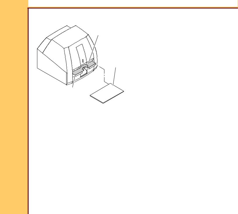
Removing the Packing Material
PROTECTIVE
FILM COVER
SHIPPING
HOLDER
CASSETTE INTERFACE
PLATEN
H195_1120ACA
H195_1120AC
1Remove the SHIPPING HOLDER.
2Cut the PROTECTIVE FILM COVER and remove from the CASSETTE INTERFACE PLATEN.

INSTALLATION INSTRUCTIONS |
Installation |
|
|
15DEC06 II4366-1 Page
9 of 91
Setting the Optional ISOLATION TRANSFORMER
OUTPUT
230 V Switch 
115 V Switch 
SET ONLY WITH
POWER OFF
230
OUTPUT SWITCH
240V |
100V |
220V |
110V |
200V |
120V |
|
|
INPUT |
|
240V |
100V |
|
|
|
220V |
|
110V |
|
200V |
120V |
|
|
INPUT SWITCH
optional ISOLATION
TRANSFORMER
H195_0088BCA
H195_0088BC
 Important
•You must set the 2 SWITCHES to the correct voltage for your region.
•You must install the ISOLATION TRANSFORMER for “Medical Electrical Equipment” installations, IEC 60601-1-1. See SPECIFICATIONS for the Kodak DirectView CR 500 SYSTEM, 1F5928.
1If necessary, use the following tables to set the INPUT and OUTPUT SWITCHES on the optional ISOLATION TRANSFORMER to the correct input and output voltage for your region.

INSTALLATION INSTRUCTIONS |
Installation |
|
|
15DEC06 II4366-1 Page 10 of 91
 Important
For systems using the optional ISOLATION TRANSFORMER with the Belkin
UNINTERRUPTIBLE POWER SUPPLY (UPS), you must use the Belkin 230 V UPS.
Table 1 Setting the SWITCHES for the optional ISOLATION TRANSFORMER with the Belkin 230 V UPS
Line |
INPUT |
OUTPUT |
Voltage |
SWITCH |
SWITCH |
|
|
|
110 |
110 |
230 |
|
|
|
115 |
110 |
230 |
|
|
|
120 |
120 |
230 |
|
|
|
127 |
120 |
230 |
|
|
|
220 |
220 |
230 |
|
|
|
230 |
220 |
230 |
|
|
|
240 |
240 |
230 |
|
|
|
Table 2 Setting the SWITCHES for the optional ISOLATION TRANSFORMER with the Desk Power 120 or 230 V UPS
Line |
INPUT |
OUTPUT |
Voltage |
SWITCH |
SWITCH |
|
|
|
110 |
110 |
115 |
|
|
|
115 |
110 |
115 |
|
|
|
120 |
120 |
115 |
|
|
|
127 |
120 |
115 |
|
|
|
220 |
220 |
230 |
|
|
|
230 |
220 |
230 |
|
|
|
240 |
240 |
230 |
|
|
|
|
INSTALLATION INSTRUCTIONS |
|
Installation |
||
|
|
|
|
|
|
15DEC06 |
Table 3 Setting the SWITCHES for the ISOLATION TRANSFORMER with the |
||||
II4366-1 |
|||||
Page |
Delta UPS - Japan only |
||||
11 of 91 |
|
|
|
|
|
|
|
Line |
INPUT |
OUTPUT |
|
|
|
Voltage |
SWITCH |
SWITCH |
|
|
|
|
|
|
|
|
100 |
100 |
115 |
|
|
|
|
|
|
|
|
|
200 |
200 |
115 |
|
|
|
|
|
|
|
|
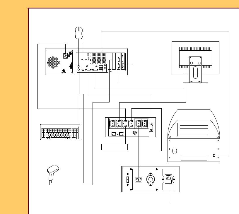
Connecting the Equipment
Figure 2 CR 500 SYSTEM - with Belkin 120 V UPS
MOUSE |
|
|
|
|
|
|
D |
|
|
A |
|
|
|
MONITOR |
C |
|
|
|
|
B |
|
|
|
|
|
|
|
F |
|
COMPUTER |
E |
K |
G |
|
|
|
|
H |
READER |
L |
|
|
J |
|
|
|
|
|
|
KEYBOARD |
|
|
|
|
|
UPS |
|
|
|
P |
O |
|
|
|
|
|
|
|
|
optional BAR |
M |
I |
|
|
|
|
|
|
|
CODE READER |
|
|
|
|
|
|
MODEM |
|
|
H195_0035DC |
|
|
|
|

|
INSTALLATION INSTRUCTIONS |
|
|
|
|
Installation |
|
15DEC06 |
Figure 3 |
CR 500 SYSTEM - with the Belkin 230 V UPS |
|||||
II4366-1 |
|||||||
Page |
|
|
|
|
|
|
|
12 of 91 |
|
MOUSE |
|
|
|
|
|
|
|
|
|
|
|
||
|
|
|
|
|
D |
|
|
|
|
A |
|
|
|
|
MONITOR |
|
|
C |
|
|
|
|
|
|
|
B |
|
|
|
|
|
|
|
|
|
|
|
F |
|
|
|
|
|
|
|
|
G |
|
|
COMPUTER |
|
|
|
|
|
|
|
|
|
E |
K |
|
H |
|
|
|
|
|
|
||
|
|
|
|
|
|
|
READER |
|
|
|
|
|
UPS |
|
|
|
|
L |
P |
O |
|
|
|
|
|
KEYBOARD |
|
|
|
|
J |
|
|
|
|
|
|
|
|
|
|
|
|
M |
I |
|
|
|
|
optional BAR |
|
|
MODEM |
|
|
|
|
CODE READER |
|
|
|
|
|
|
|
|
|
|
240V |
100V |
|
|
|
|
|
|
220V |
110V |
|
|
|
|
|
|
200V |
120V |
|
|
|
|
|
|
optional ISOLATION |
N |
|
|
|
|
|
|
TRANSFORMER |
H195_0037DC |
|

|
INSTALLATION INSTRUCTIONS |
|
|
|
|
|
Installation |
|
15DEC06 |
Figure 4 |
CR 500 SYSTEM - with the Desk Power 120 V UPS - RS-232 Connection |
||||||
II4366-1 |
||||||||
Page |
|
|
|
|
|
|
|
|
13 of 91 |
|
MOUSE |
|
D |
|
|
|
|
|
|
|
|
|
|
|
|
|
|
|
A |
|
|
|
|
|
MONITOR |
|
|
C |
|
|
|
|
|
|
|
|
B |
|
|
|
|
|
|
|
|
|
|
|
F |
|
|
|
|
|
COMPUTER |
|
|
K |
G |
|
|
|
|
|
|
|
|
|
|
|
|
|
|
|
|
E |
|
|
|
|
|
|
|
|
|
|
H |
READER |
|
|
|
|
|
|
|
|
|
|
|
L |
|
|
UPS |
|
J |
|
|
|
|
|
|
|
|
||
|
|
KEYBOARD |
|
|
|
|
|
|
|
|
|
P |
O |
I |
|
|
|
|
|
optional BAR |
|
|
M |
|
|
|
|
|
CODE READER |
|
|
|
|
|
|
|
|
|
|
|
|
|
|
|
|
|
|
|
|
MODEM |
|
|
|
|
|
|
|
|
240V |
100V |
|
|
|
|
|
|
|
220V |
110V |
|
|
|
|
|
|
|
V |
21 |
|
|
|
|
|
|
|
020 |
V0 |
|
|
|
H195_0089DC |
|
|
optional ISOLATION |
N |
|
||
|
|
|
TRANSFORMER |
|
|
|||
|
|
|
|
|
|
|
||
|
INSTALLATION INSTRUCTIONS |
|
|
|
|
Installation |
15DEC06 |
Figure 5 CR 500 SYSTEM - with the Desk Power 230 V UPS - RS-232 Connection |
|||||
II4366-1 |
||||||
Page |
|
|
|
|
|
|
14 of 91 |
MOUSE |
|
|
|
|
|
|
|
|
|
|
||
|
|
|
D |
|
|
|
|
A |
|
|
|
|
MONITOR |
|
C |
|
|
|
|
|
|
B |
|
|
|
|
|
|
|
|
|
F |
|
|
|
COMPUTER |
E |
K |
|
|
|
|
|
|
|
|
||
|
|
|
|
G |
|
|
|
|
|
|
|
|
|
|
|
|
|
|
|
H |
|
|
|
|
|
|
READER |
|
|
|
UPS |
|
|
J |
|
L |
|
|
|
|
|
|
|
|
|
|
|
|
|
KEYBOARD |
|
|
|
|
|
|
|
|
|
I |
|
|
|
optional BAR |
|
MODEM |
M |
|
|
|
|
|
|
|
|
|
|
CODE READER |
|
|
|
|
|
|
P |
|
O |
|
|
|
|
|
|
|
240V |
100V |
|
|
|
|
|
220V |
110V |
|
|
|
|
|
200V |
120V |
|
|
|
|
|
optional ISOLATION |
N |
|
|
H195_0090DC |
|
|
TRANSFORMER |
|
|

|
INSTALLATION INSTRUCTIONS |
|
|
|
Installation |
15DEC06 |
Figure 6 CR 500 SYSTEM - IBM Model 8212 Computer - with the Desk Power 120 V UPS - |
||||
II4366-1 |
|||||
Page |
USB Connection |
|
|
|
|
15 of 91 |
|
|
|
|
|
|
|
|
|
|
D |
|
|
|
F |
MOUSE |
|
|
COMPUTER |
|
|
|
MONITOR |
|
|
|
|
|
|
|
A |
|
|
|
|
|
|
com1 |
com3 |
B |
|
|
|
|
|
|
|
|
|
|
com4 |
|
|
|
|
|
|
K |
|
|
E |
|
|
|
G |
|
|
|
|
|
|
|
|
|
|
|
H |
|
|
|
|
|
READER |
|
|
|
UPS |
|
|
|
L |
P |
O |
|
|
|
KEYBOARD |
|
|
|
J |
|
|
|
|
|
|
|
|
|
M |
I |
|
|
optional BAR |
|
MODEM |
|
|
|
CODE READER |
|
|||
|
|
|
|
||
|
|
|
240V |
100V |
|
|
|
|
220V |
110V |
|
|
|
|
V |
21 |
|
|
|
|
002 |
V0 |
|
|
|
|
optional ISOLATION |
N |
|
|
|
|
TRANSFORMER |
H195_0095DC |
|

|
INSTALLATION INSTRUCTIONS |
|
|
|
Installation |
15DEC06 |
Figure 7 CR 500 SYSTEM - IBM Model 8212 Computer - with the Desk Power 230 V UPS - |
||||
II4366-1 |
|||||
Page |
USB Connection |
|
|
|
|
16 of 91 |
|
|
|
|
|
|
|
|
|
|
D |
|
|
|
F |
MOUSE |
|
|
COMPUTER |
|
|
|
MONITOR |
|
|
|
|
|
|
|
A |
|
|
|
|
|
|
com1 |
com3 |
B |
|
|
|
|
|
|
|
|
|
|
com4 |
|
|
|
|
|
|
K |
|
|
E |
|
|
|
G |
|
|
|
|
|
|
|
|
|
|
|
H |
|
|
|
|
|
READER |
|
|
|
UPS |
|
|
|
L |
P |
O |
|
|
|
KEYBOARD |
|
|
|
J |
|
|
|
|
|
|
|
|
|
M |
I |
|
|
optional BAR |
|
|
MODEM |
|
|
CODE READER |
|
|
||
|
|
|
240V |
100V |
|
|
|
|
220V |
110V |
|
|
|
|
V0 02 |
21 |
|
|
|
|
V0 |
|
|
|
|
|
optional ISOLATION |
N |
|
|
|
|
TRANSFORMER |
H195_0096DC |
|
|
|
|
|
||

INSTALLATION INSTRUCTIONS |
Installation |
|
|
15DEC06 II4366-1 Page 17 of 91
Figure 8 CR 500 SYSTEM - Japan only with the Delta UPS
MOUSE
D
A |
MONITOR |
|
C |
||
B |
||
|
F |
COMPUTER |
K |
|
E |
||
G |
||
|
H |
|
|
READER |
|
L |
|
|
KEYBOARD |
|
|
I |
|
|
|
MODEM |
|
|
|
|
|
|
J |
|
|
P |
O |
|
|
|
optional BAR |
|
|
|
|
CODE READER |
M |
|
|
|
|
240V |
100V |
|
|
|
|
220V |
110V |
|
|
|
00V2 |
120V |
|
|
|
ISOLATION |
N |
|
H195_0091DC |
|
TRANSFORMER |
||
|
|
|||
 Caution
•On computers with 2 COM PORTS on the MOTHER BOARD, COM 1 is next to the
MONITOR CONNECTOR.
•Dangerous Voltage

INSTALLATION INSTRUCTIONS |
Installation |
|
|
15DEC06 II4366-1 Page 18 of 91
1 Connect:
Item |
CABLE |
From: |
To: |
|
Notes |
A |
POWER |
COMPUTER |
UPS |
|
|
|
|
|
|
|
|
B |
MOUSE |
MOUSE |
COMPUTER |
|
|
|
|
|
|
|
|
C |
MODEM - optional |
MODEM |
COMPUTER COM 2 |
• |
2.4 GHz only |
|
|
|
|
• |
Only used on |
|
|
|
|
|
PCs with a RS- |
|
|
|
|
|
232 UPS |
|
|
|
|
|
|
D |
INTERNAL |
COMPUTER |
READER |
|
|
|
NETWORK |
|
|
|
|
|
|
|
|
|
|
E |
UPS |
COM 1 |
UPS |
Use only the top |
|
|
COMMUNICATION |
|
|
USB Port. |
|
|
|
|
|
|
|
F |
HOSPITAL |
network |
COMPUTER |
|
|
|
NETWORK |
|
|
|
|
|
|
|
|
|
|
G |
MONITOR |
MONITOR |
MONITOR |
|
|
|
|
|
CONNECTOR |
|
|
|
|
|
|
|
|
H |
MONITOR POWER |
MONITOR |
UPS |
|
|
|
|
|
|
|
|
I |
MODEM POWER - |
MODEM |
UPS |
|
|
|
optional |
|
|
|
|
|
|
|
|
|
|
J |
SYSTEM POWER |
CR 500 SYSTEM |
UPS |
|
|
|
|
|
|
|
|
K |
MODEM - optional |
MODEM |
COMPUTER COM 4 |
3.0 GHz only |
|
|
|
|
|
|
|
L |
KEYBOARD |
KEYBOARD |
KEYBOARD |
|
|
|
|
|
CONNECTOR |
|
|
|
|
|
|
|
|
M |
POWER |
UPS |
• power source |
Do not connect at |
|
|
|
|
• ISOLATION |
this time. |
|
|
|
|
|
|
|
|
|
|
TRANSFORMER |
|
|
|
|
|
|
|
|
N |
POWER |
ISOLATION |
power source |
Do not connect at |
|
|
|
TRANSFORMER |
|
this time. |
|
|
|
|
|
|
|
INSTALLATION INSTRUCTIONS |
Installation |
|
|
15DEC06 II4366-1 Page 19 of 91
Item |
CABLE |
From: |
To: |
Notes |
O |
BARCODE READER - |
BARCODE |
COMPUTER COM 3 |
|
|
optional |
READER |
|
|
|
|
|
|
|
P |
BARCODE READER - |
BARCODE |
KEYBOARD |
|
|
optional |
READER |
CONNECTOR |
|
|
|
|
|
|
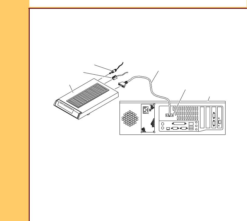
Installing the Optional MODEM
POWER ADAPTER
RS-232 CABLE
telephone line
MODEM
COM 2
COMPUTER
H195_0032BCA
H195_0032BC
1Remove the MODEM from the carton.
2Connect:
•POWER ADAPTER to the back of the MODEM
•telephone line to the MODEM
•RS-232 CABLE to:
–MODEM
–COM 2 for 2.4 GHz computer only
–Com 4 for 3.0 GHz computer only

INSTALLATION INSTRUCTIONS |
Installation |
|
|
15DEC06 II4366-1 Page 20 of 91
 Caution
Dangerous Voltage
3Connect the POWER ADAPTER to the power source.
4Energize the MODEM.
Installing the DVD/CD WRITER
CPU COVER |
Caution |
2 BUTTONS |
|
Dangerous Voltage |
|
1 |
De-energize the computer. |
2 |
Press the 2 BUTTONS. |
3 |
Remove the CPU COVER from the |
|
CPU. |
CPU |
H195_1092ACA |
H195_1092AC |
INSTALLATION INSTRUCTIONS |
Installation |
|
|
15DEC06 II4366-1 Page
21 of 91
DVD WRITER
JUMPER
PIN 7
H195_0055BCA
H195_0055BC
4 Move the JUMPER to PIN 7 on the DVD WRITER.

INSTALLATION INSTRUCTIONS |
Installation |
||
15DEC06 |
|
|
|
II4366-1 |
|
|
|
Page |
|
|
|
22 of 91 |
|
|
|
|
|
DVD WRITER |
|
|
|
|
POWER |
|
|
|
CABLE |
|
|
|
IDE CABLE |
|
|
2 SCREWS |
H195_0054HCA |
|
|
H195_0054HC |
|
5 |
Install: |
|
|
|
• |
DVD WRITER |
|
|
• |
2 SCREWS |
|
6 |
Connect the CABLES: |
|
|
|
• |
IDE |
|
|
• |
POWER |
|
7 |
Install the CPU COVER. |
|
|

INSTALLATION INSTRUCTIONS |
Installation |
|
|
15DEC06 II4366-1 Page 23 of 91
Connecting the Power
 Caution
Dangerous Voltage
1 Does your system have an ISOLATION TRANSFORMER installed?
Yes |
No |
|
a. Connect: |
a. Connect the UPS POWER CABLE to the |
|
• UPS POWER CABLE to the |
power source. |
|
b. Continue with Step 2. |
||
ISOLATION TRANSFORMER |
•ISOLATION TRANSFORMER
POWER CABLE to the power source.
b.Continue with Step 2.
2 Connect the system to the network connection at the site.
INSTALLATION INSTRUCTIONS |
Installation |
|
|
15DEC06 II4366-1 Page 24 of 91
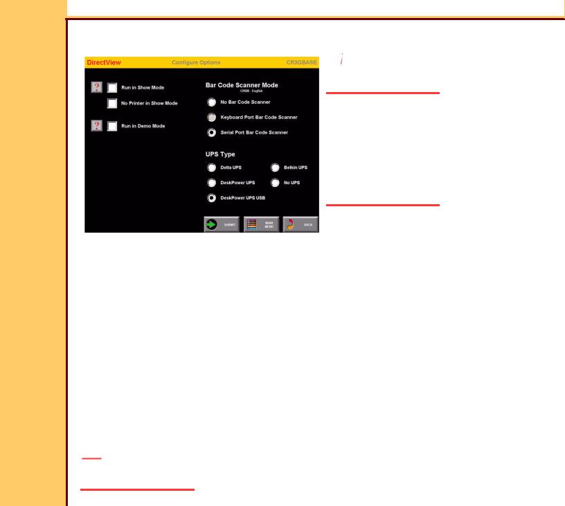
Setting the Configurations Options
 Caution
Dangerous Voltage
1 Energize the system.
 Important
For systems with software version ≥ 4.1, you must have a “Session ID” for access to
“Service Functions” and “Diagnostics”. See
SERVICE BULLETIN 843.
2 From the main menu, click:
• [Service Functions]
• [Configure Options]
• [Serial Port Bar Code Scanner]
3Under the “UPS Type”, select the check box for the corresponding UPS installed in your system:
Check Box |
UPS |
Delta UPS |
Japan only |
|
|
DeskPower UPS |
650 VA - RS232 Port |
|
|
DeskPower UPS USB |
650 VA - USB Port |
|
|
Belkin UPS |
Belkin UPS |
|
|
No UPS |
No UPS used |
|
|
4If necessary, under the “Bar Code Scanner Mode” select the corresponding check box.
5Click [Submit].
 Note
Note
The system restarts.

INSTALLATION INSTRUCTIONS |
Installation |
|
|
15DEC06 II4366-1 Page 25 of 91
Doing the Setup
Checking the MIMDUI Configuration of the LOCALHOST
1At the main menu, click:
•[Service Functions]
•[Service Utilities]
•[Exit to Desktop]
2Double-click the “MIMDUI” icon.
3Select:
•Configure>Connect to MIM
•Configure>Destination
4Check that “LOCALHOST” appears in the list of “Available Destinations”.
5Select:
•[LOCALHOST]
•[Modify]
6Check the following setting:
Field |
Parameter |
Logical Name |
LOCALHOST |
|
|
IP Address |
127.0.0.1 |
|
|
Port Number |
104 |
|
|
AE Title |
LOCALHOST |
|
|
Response Message |
130 |
|
|
Association Retry |
1 |
Counter |
|
|
|
“Modality LUT” on the SCU screen is checked

INSTALLATION INSTRUCTIONS |
Installation |
|
|
15DEC06 II4366-1 Page 26 of 91
7 Is the information correct?
Yes |
No |
|
|
Advance to Setting the Configuration of the DVD DRIVE. Continue with Step Step 8.
8Select Add>Store>Qualified.
9Click:
•[AutoRad WS]
•[OK]
10For:
•“Logical Name” type: LOCALHOST
•“IP Address” type: 127.0.0.1
11Click [Next].
12Type the following information for the Parameters:
Field |
Parameter |
Port Number |
104 |
|
|
AE Title |
LOCALHOST |
|
|
Response Message |
130 |
|
|
Association Retry |
1 |
Counter |
|
|
|
13Click:
•[Next]
•[Next]
•[Next]
14At the “SCU” screen, check that the “Modality LUT” check box is selected.

INSTALLATION INSTRUCTIONS
15DEC06 |
15 Click: |
|
II4366-1 |
||
Page |
• |
[Next] |
27 of 91 |
||
|
• |
[Finish] |
|
• |
[Close] |
16Select Connect>Disconnect.
17If prompted, insert the MIM BACKUP DISK.
18Click [OK].
19Select:
•Connect>Exit.
•Start>Shutdown>Restart
Adding the CD/DVD DESTINATION to the MIM
1Log on to the service menu.
2At the main menu, click:
•[Service Functions]
•[Service Utilities]
•[Exit to Desktop]
3Check that “RNI” is running.
4If “RNI” is not running:
aSelect Start>Run.
bType: rni.exe
cClick [OK].
5Double-click the “MIMDUI” icon.
6Select Configure>Connect to MIM.
7Wait for the “MIMDUI” screen to appear.
Installation

INSTALLATION INSTRUCTIONS |
Installation |
|
|
15DEC06 II4366-1 Page 28 of 91
8Select:
•Configure>Destination
•New>Store>Qualified
9Select “AutoRad WS”.
10Click [OK].
Loading...