


 Loading...
{ServiceManual}{Production}{Health Group}{Internal} |
Publication No. 6H4866-02 |
|
|
|
JUN2008 |
|
Service Manual |
|
for the |
|
Kodak Point-of-Care CR 120/140 Systems |
 Important
When doing the procedures in this document, you must use safe work practices and wear the correct Personal Protective Equipment (i.e. SAFETY EYEWEAR) according to your Company’s Standard Operating Procedures.
© CARESTREAM HEALTH, INC. 2008

Point-of-Care CR 120/140 Service Manual
Publication Number: 6H4866-02
© Carestream Health, Inc. 2008
All rights reserved. No part of this manual may be reproduced or copied in any form by any means -graphic, electronic or mechanical, including photocopying, typing, or information retrieval systems -without written permission of Carestream Health.
Use of the Guide
The Kodak Point-of-Care CR 120/140 System is designed to meet international safety and performance standards. Personnel operating the unit must have a thorough understanding of the proper operation of the system. This manual has been prepared to aid medical and technical personnel to understand and operate the system. Do not operate the system before reading this manual and gaining a clear understanding of the operation of the system. If any part of this manual is not clear, please contact your Carestream Health representative for clarification.
Authorized European Representative
Carestream Health France LES MERCURIALES
40, rue Jean Jaures
93176 BAGNOLET CEDEX France
CARESTREAM is a trademark of Carestream Health.
KODAK is a trademark of Kodak used under license.
Carestream Health, Inc.
150 Verona Street
Rochester, NY 14608
2 |
6H4866-02 |

Table of Contents |
|
Description |
Page |
Safety and Regulatory Information . . . . . . . . . . . . . . . . . . . . . . . . . . . . . . . . . . . . . . . . . . . |
11 |
Introduction . . . . . . . . . . . . . . . . . . . . . . . . . . . . . . . . . . . . . . . . . . . . . . . . . . . . . . . . . |
11 |
General Safety Guidelines . . . . . . . . . . . . . . . . . . . . . . . . . . . . . . . . . . . . . . . . . . . . . |
11 |
Electrical Hazards. . . . . . . . . . . . . . . . . . . . . . . . . . . . . . . . . . . . . . . . . . . . . . . . . . . . |
12 |
Explosion and Implosion Hazards . . . . . . . . . . . . . . . . . . . . . . . . . . . . . . . . . . . . . . . |
12 |
Overheating . . . . . . . . . . . . . . . . . . . . . . . . . . . . . . . . . . . . . . . . . . . . . . . . . . . . . . . . |
12 |
Laser Safety Instructions . . . . . . . . . . . . . . . . . . . . . . . . . . . . . . . . . . . . . . . . . . . . . . |
12 |
Recycling the Unit. . . . . . . . . . . . . . . . . . . . . . . . . . . . . . . . . . . . . . . . . . . . . . . . . . . . |
12 |
Labelling Summary . . . . . . . . . . . . . . . . . . . . . . . . . . . . . . . . . . . . . . . . . . . . . . . . . . . |
13 |
IEC Symbols Used . . . . . . . . . . . . . . . . . . . . . . . . . . . . . . . . . . . . . . . . . . . . . . . . . . . |
13 |
Device-specific Safety Information . . . . . . . . . . . . . . . . . . . . . . . . . . . . . . . . . . . . . . . |
14 |
Regulatory Information . . . . . . . . . . . . . . . . . . . . . . . . . . . . . . . . . . . . . . . . . . . . . . . . |
14 |
System Description. . . . . . . . . . . . . . . . . . . . . . . . . . . . . . . . . . . . . . . . . . . . . . . . . . . . . . . |
15 |
Introduction . . . . . . . . . . . . . . . . . . . . . . . . . . . . . . . . . . . . . . . . . . . . . . . . . . . . . . . . . |
15 |
Operational Principles. . . . . . . . . . . . . . . . . . . . . . . . . . . . . . . . . . . . . . . . . . . . . . . . . |
15 |
System Overview . . . . . . . . . . . . . . . . . . . . . . . . . . . . . . . . . . . . . . . . . . . . . . . . . . . . |
15 |
Component Description . . . . . . . . . . . . . . . . . . . . . . . . . . . . . . . . . . . . . . . . . . . . . . . |
20 |
Service Procedures . . . . . . . . . . . . . . . . . . . . . . . . . . . . . . . . . . . . . . . . . . . . . . . . . . . . . . |
41 |
Service Tools . . . . . . . . . . . . . . . . . . . . . . . . . . . . . . . . . . . . . . . . . . . . . . . . . . . . . . . |
41 |
Removing the Service Panel and Scanner Cover . . . . . . . . . . . . . . . . . . . . . . . . . . . |
41 |
Disconnecting the Laser . . . . . . . . . . . . . . . . . . . . . . . . . . . . . . . . . . . . . . . . . . . . . . . |
44 |
Replacing the Fuses . . . . . . . . . . . . . . . . . . . . . . . . . . . . . . . . . . . . . . . . . . . . . . . . . . |
45 |
Power Inlet Module Replacement. . . . . . . . . . . . . . . . . . . . . . . . . . . . . . . . . . . . . . . . |
46 |
USB Board Replacement . . . . . . . . . . . . . . . . . . . . . . . . . . . . . . . . . . . . . . . . . . . . . . |
48 |
Motion Board Replacement . . . . . . . . . . . . . . . . . . . . . . . . . . . . . . . . . . . . . . . . . . . . |
50 |
Sensor Board Replacement . . . . . . . . . . . . . . . . . . . . . . . . . . . . . . . . . . . . . . . . . . . . |
51 |
PM Tube and PM Board Replacement . . . . . . . . . . . . . . . . . . . . . . . . . . . . . . . . . . . . |
52 |
Laser Board Replacement . . . . . . . . . . . . . . . . . . . . . . . . . . . . . . . . . . . . . . . . . . . . . |
54 |
Roller Motor Replacement . . . . . . . . . . . . . . . . . . . . . . . . . . . . . . . . . . . . . . . . . . . . . |
56 |
Linear Slide Assembly Replacement . . . . . . . . . . . . . . . . . . . . . . . . . . . . . . . . . . . . . |
59 |
Loader Stepper Motor Replacement. . . . . . . . . . . . . . . . . . . . . . . . . . . . . . . . . . . . . . |
63 |
Power Supply Assembly Replacement. . . . . . . . . . . . . . . . . . . . . . . . . . . . . . . . . . . . |
66 |
Erase Lamps Assembly Replacement . . . . . . . . . . . . . . . . . . . . . . . . . . . . . . . . . . . . |
70 |
Erase Lamps Inverters Replacement . . . . . . . . . . . . . . . . . . . . . . . . . . . . . . . . . . . . . |
73 |
Erase Lamps Sensors Replacement . . . . . . . . . . . . . . . . . . . . . . . . . . . . . . . . . . . . . |
75 |
Left Limit Sensor Replacement. . . . . . . . . . . . . . . . . . . . . . . . . . . . . . . . . . . . . . . . . . |
77 |
Right Limit Sensor Replacement . . . . . . . . . . . . . . . . . . . . . . . . . . . . . . . . . . . . . . . . |
79 |
Screen Size Sensor Replacement . . . . . . . . . . . . . . . . . . . . . . . . . . . . . . . . . . . . . . . |
80 |
Roller Sensor Replacement . . . . . . . . . . . . . . . . . . . . . . . . . . . . . . . . . . . . . . . . . . . . |
82 |
Z0 Sensor Replacement. . . . . . . . . . . . . . . . . . . . . . . . . . . . . . . . . . . . . . . . . . . . . . . |
83 |
W0 Sensors Replacement (Top/Receiver and Bottom/Transmitter). . . . . . . . . . . . . . |
85 |
Screen Guide Replacement for non Auto-loop systems. . . . . . . . . . . . . . . . . . . . . . . |
89 |
Auto-loop Key Assembly Replacement . . . . . . . . . . . . . . . . . . . . . . . . . . . . . . . . . . . |
94 |
Auto-loop Solenoid Replacement . . . . . . . . . . . . . . . . . . . . . . . . . . . . . . . . . . . . . . . . |
97 |
Tray Assembly Replacement for non Auto-loop Systems . . . . . . . . . . . . . . . . . . . . . |
98 |
Tray Assembly Replacement for Auto-loop Systems . . . . . . . . . . . . . . . . . . . . . . . . . |
103 |
Calibrations. . . . . . . . . . . . . . . . . . . . . . . . . . . . . . . . . . . . . . . . . . . . . . . . . . . . . . . . . . . . . |
107 |
Nominal Calibration . . . . . . . . . . . . . . . . . . . . . . . . . . . . . . . . . . . . . . . . . . . . . . . . . . |
107 |
Facility Calibrations for Kodak QC Version 2.1.2/2.4.2 Software . . . . . . . . . . . . . . . |
115 |
Gain Tuning Calibration Process for Kodak QC Version 2.5 . . . . . . . . . . . . . . . . . . . |
123 |
Adjustments . . . . . . . . . . . . . . . . . . . . . . . . . . . . . . . . . . . . . . . . . . . . . . . . . . . . . . . . . . . . |
127 |
Auto-loop Solenoid Adjustment . . . . . . . . . . . . . . . . . . . . . . . . . . . . . . . . . . . . . . . . . |
127 |
Screen Guide Adjustment (non Auto-loop) . . . . . . . . . . . . . . . . . . . . . . . . . . . . . . . . . |
129 |
Loader Pin and Loader Pusher Adjustments . . . . . . . . . . . . . . . . . . . . . . . . . . . . . . . |
132 |
6H4866-02 |
3 |

Roller Sensor Adjustment . . . . . . . . . . . . . . . . . . . . . . . . . . . . . . . . . . . . . . . . . . . . . 135
Electric Schematic Diagrams . . . . . . . . . . . . . . . . . . . . . . . . . . . . . . . . . . . . . . . . . . . . . . . 137
Preventive Maintenance. . . . . . . . . . . . . . . . . . . . . . . . . . . . . . . . . . . . . . . . . . . . . . . . . . . 145
Cleaning the Rollers. . . . . . . . . . . . . . . . . . . . . . . . . . . . . . . . . . . . . . . . . . . . . . . . . . 145
Cleaning the Phosphor Screens . . . . . . . . . . . . . . . . . . . . . . . . . . . . . . . . . . . . . . . . 149
Publication History . . . . . . . . . . . . . . . . . . . . . . . . . . . . . . . . . . . . . . . . . . . . . . . . . . . . . . . 155
List of Figures |
|
Description |
Page |
Block Diagram of the Point-of-Care CR 120/140 . . . . . . . . . . . . . . . . . . . . . . . . . . . . . . . . |
17 |
Scanner Front View . . . . . . . . . . . . . . . . . . . . . . . . . . . . . . . . . . . . . . . . . . . . . . . . . . . . . . |
18 |
Scanner Rear View . . . . . . . . . . . . . . . . . . . . . . . . . . . . . . . . . . . . . . . . . . . . . . . . . . . . . . |
18 |
Scanner Left View . . . . . . . . . . . . . . . . . . . . . . . . . . . . . . . . . . . . . . . . . . . . . . . . . . . . . . . |
19 |
Scanner Right View . . . . . . . . . . . . . . . . . . . . . . . . . . . . . . . . . . . . . . . . . . . . . . . . . . . . . . |
19 |
USB Board . . . . . . . . . . . . . . . . . . . . . . . . . . . . . . . . . . . . . . . . . . . . . . . . . . . . . . . . . . . . . |
20 |
Motion Board . . . . . . . . . . . . . . . . . . . . . . . . . . . . . . . . . . . . . . . . . . . . . . . . . . . . . . . . . . . |
21 |
Sensor Board . . . . . . . . . . . . . . . . . . . . . . . . . . . . . . . . . . . . . . . . . . . . . . . . . . . . . . . . . . . |
22 |
PM and PM Board . . . . . . . . . . . . . . . . . . . . . . . . . . . . . . . . . . . . . . . . . . . . . . . . . . . . . . . |
24 |
Laser Board . . . . . . . . . . . . . . . . . . . . . . . . . . . . . . . . . . . . . . . . . . . . . . . . . . . . . . . . . . . . |
25 |
Laser . . . . . . . . . . . . . . . . . . . . . . . . . . . . . . . . . . . . . . . . . . . . . . . . . . . . . . . . . . . . . . . . . |
26 |
Roller Motor . . . . . . . . . . . . . . . . . . . . . . . . . . . . . . . . . . . . . . . . . . . . . . . . . . . . . . . . . . . . |
27 |
Roller Motor Connector . . . . . . . . . . . . . . . . . . . . . . . . . . . . . . . . . . . . . . . . . . . . . . . . . . . |
27 |
Linear Slide Assembly . . . . . . . . . . . . . . . . . . . . . . . . . . . . . . . . . . . . . . . . . . . . . . . . . . . . |
28 |
Linear Slide Stepper Motor Connector. . . . . . . . . . . . . . . . . . . . . . . . . . . . . . . . . . . . . . . . |
28 |
Carriage Stepper Motor . . . . . . . . . . . . . . . . . . . . . . . . . . . . . . . . . . . . . . . . . . . . . . . . . . . |
29 |
Carriage Stepper Motor Wiring . . . . . . . . . . . . . . . . . . . . . . . . . . . . . . . . . . . . . . . . . . . . . |
29 |
Power Supply Assembly . . . . . . . . . . . . . . . . . . . . . . . . . . . . . . . . . . . . . . . . . . . . . . . . . . |
30 |
Auto-loop Key Assembly and Tray Assembly . . . . . . . . . . . . . . . . . . . . . . . . . . . . . . . . . . |
31 |
Auto-loop Key Assembly . . . . . . . . . . . . . . . . . . . . . . . . . . . . . . . . . . . . . . . . . . . . . . . . . . |
31 |
Erase Lamps . . . . . . . . . . . . . . . . . . . . . . . . . . . . . . . . . . . . . . . . . . . . . . . . . . . . . . . . . . . |
32 |
Erase Lamp Assembly . . . . . . . . . . . . . . . . . . . . . . . . . . . . . . . . . . . . . . . . . . . . . . . . . . . . |
32 |
Erase Lamps Inverter Assembly . . . . . . . . . . . . . . . . . . . . . . . . . . . . . . . . . . . . . . . . . . . . |
33 |
Inverter Assembly Connections . . . . . . . . . . . . . . . . . . . . . . . . . . . . . . . . . . . . . . . . . . . . . |
33 |
Erase Lamp Sensor . . . . . . . . . . . . . . . . . . . . . . . . . . . . . . . . . . . . . . . . . . . . . . . . . . . . . . |
34 |
Erase Lamp Sensor Connectors . . . . . . . . . . . . . . . . . . . . . . . . . . . . . . . . . . . . . . . . . . . . |
34 |
Left Limit Sensor . . . . . . . . . . . . . . . . . . . . . . . . . . . . . . . . . . . . . . . . . . . . . . . . . . . . . . . . |
35 |
Right Limit Sensor . . . . . . . . . . . . . . . . . . . . . . . . . . . . . . . . . . . . . . . . . . . . . . . . . . . . . . . |
35 |
Screen Size Sensor . . . . . . . . . . . . . . . . . . . . . . . . . . . . . . . . . . . . . . . . . . . . . . . . . . . . . . |
36 |
Roller Sensor . . . . . . . . . . . . . . . . . . . . . . . . . . . . . . . . . . . . . . . . . . . . . . . . . . . . . . . . . . . |
37 |
4 |
6H4866-02 |

Z0 Sensor . . . . . . . . . . . . . . . . . . . . . . . . . . . . . . . . . . . . . . . . . . . . . . . . . . . . . . . . . . . . . . |
38 |
Top WO Sensor . . . . . . . . . . . . . . . . . . . . . . . . . . . . . . . . . . . . . . . . . . . . . . . . . . . . . . . . . |
39 |
Bottom W0 Sensor . . . . . . . . . . . . . . . . . . . . . . . . . . . . . . . . . . . . . . . . . . . . . . . . . . . . . . . |
39 |
Service Panel Screws. . . . . . . . . . . . . . . . . . . . . . . . . . . . . . . . . . . . . . . . . . . . . . . . . . . . . |
41 |
Access to Cover Screws. . . . . . . . . . . . . . . . . . . . . . . . . . . . . . . . . . . . . . . . . . . . . . . . . . . |
42 |
Cover Screws . . . . . . . . . . . . . . . . . . . . . . . . . . . . . . . . . . . . . . . . . . . . . . . . . . . . . . . . . . . |
42 |
Laser Connector on the Laser Board . . . . . . . . . . . . . . . . . . . . . . . . . . . . . . . . . . . . . . . . . |
44 |
Location of Fuses . . . . . . . . . . . . . . . . . . . . . . . . . . . . . . . . . . . . . . . . . . . . . . . . . . . . . . . . |
45 |
Nuts Securing the Module . . . . . . . . . . . . . . . . . . . . . . . . . . . . . . . . . . . . . . . . . . . . . . . . . |
46 |
Line Filter Wire Attached to Ground . . . . . . . . . . . . . . . . . . . . . . . . . . . . . . . . . . . . . . . . . . |
47 |
Side View of Power Module Showing Connection Tabs. . . . . . . . . . . . . . . . . . . . . . . . . . . |
47 |
USB Cover . . . . . . . . . . . . . . . . . . . . . . . . . . . . . . . . . . . . . . . . . . . . . . . . . . . . . . . . . . . . . |
48 |
USB Board Connectors . . . . . . . . . . . . . . . . . . . . . . . . . . . . . . . . . . . . . . . . . . . . . . . . . . . |
48 |
Motion Board Bracket Screws . . . . . . . . . . . . . . . . . . . . . . . . . . . . . . . . . . . . . . . . . . . . . . |
50 |
Motion Board Connectors. . . . . . . . . . . . . . . . . . . . . . . . . . . . . . . . . . . . . . . . . . . . . . . . . . |
50 |
Sensor Board Connections. . . . . . . . . . . . . . . . . . . . . . . . . . . . . . . . . . . . . . . . . . . . . . . . . |
51 |
Sensor Board Screws. . . . . . . . . . . . . . . . . . . . . . . . . . . . . . . . . . . . . . . . . . . . . . . . . . . . . |
51 |
PM Ground Wire. . . . . . . . . . . . . . . . . . . . . . . . . . . . . . . . . . . . . . . . . . . . . . . . . . . . . . . . . |
52 |
Connector to the PM Board . . . . . . . . . . . . . . . . . . . . . . . . . . . . . . . . . . . . . . . . . . . . . . . . |
52 |
PM Assembly Screw (one side shown) . . . . . . . . . . . . . . . . . . . . . . . . . . . . . . . . . . . . . . . |
53 |
PM Assembly Lower Screw . . . . . . . . . . . . . . . . . . . . . . . . . . . . . . . . . . . . . . . . . . . . . . . . |
53 |
Laser Board Connectors. . . . . . . . . . . . . . . . . . . . . . . . . . . . . . . . . . . . . . . . . . . . . . . . . . . |
54 |
Laser Board Screws . . . . . . . . . . . . . . . . . . . . . . . . . . . . . . . . . . . . . . . . . . . . . . . . . . . . . . |
54 |
Laser Operation . . . . . . . . . . . . . . . . . . . . . . . . . . . . . . . . . . . . . . . . . . . . . . . . . . . . . . . . . |
55 |
Roller Motor Connector . . . . . . . . . . . . . . . . . . . . . . . . . . . . . . . . . . . . . . . . . . . . . . . . . . . |
56 |
Roller Motor Screws . . . . . . . . . . . . . . . . . . . . . . . . . . . . . . . . . . . . . . . . . . . . . . . . . . . . . . |
56 |
Roller Motor Drive retaining screw . . . . . . . . . . . . . . . . . . . . . . . . . . . . . . . . . . . . . . . . . . . |
57 |
Roller Motor Drive. . . . . . . . . . . . . . . . . . . . . . . . . . . . . . . . . . . . . . . . . . . . . . . . . . . . . . . . |
57 |
Drive Adaptor . . . . . . . . . . . . . . . . . . . . . . . . . . . . . . . . . . . . . . . . . . . . . . . . . . . . . . . . . . . |
57 |
Operating the Roller Motor . . . . . . . . . . . . . . . . . . . . . . . . . . . . . . . . . . . . . . . . . . . . . . . . . |
58 |
Connector to USB Board . . . . . . . . . . . . . . . . . . . . . . . . . . . . . . . . . . . . . . . . . . . . . . . . . . |
59 |
Laser Board Cable and Connectors . . . . . . . . . . . . . . . . . . . . . . . . . . . . . . . . . . . . . . . . . . |
59 |
Stepper Motor and Left Limit Sensor Connectors . . . . . . . . . . . . . . . . . . . . . . . . . . . . . . . |
60 |
Right Limit Sensor Connector. . . . . . . . . . . . . . . . . . . . . . . . . . . . . . . . . . . . . . . . . . . . . . . |
60 |
Screw Attaching the Ground Wire . . . . . . . . . . . . . . . . . . . . . . . . . . . . . . . . . . . . . . . . . . . |
60 |
Slide Assembly Attaching Screws . . . . . . . . . . . . . . . . . . . . . . . . . . . . . . . . . . . . . . . . . . . |
61 |
Slide Assembly . . . . . . . . . . . . . . . . . . . . . . . . . . . . . . . . . . . . . . . . . . . . . . . . . . . . . . . . . . |
61 |
Linear Slide Test. . . . . . . . . . . . . . . . . . . . . . . . . . . . . . . . . . . . . . . . . . . . . . . . . . . . . . . . . |
62 |
Connector J505 on the Connector Board . . . . . . . . . . . . . . . . . . . . . . . . . . . . . . . . . . . . . . |
63 |
6H4866-02 |
5 |

Stepper Motor Cable . . . . . . . . . . . . . . . . . . . . . . . . . . . . . . . . . . . . . . . . . . . . . . . . . . . . . |
63 |
Bottom of Unit . . . . . . . . . . . . . . . . . . . . . . . . . . . . . . . . . . . . . . . . . . . . . . . . . . . . . . . . . . |
64 |
Pulling the Carriage Down . . . . . . . . . . . . . . . . . . . . . . . . . . . . . . . . . . . . . . . . . . . . . . . . . |
64 |
Carriage Assembly Attaching Screws . . . . . . . . . . . . . . . . . . . . . . . . . . . . . . . . . . . . . . . . |
64 |
Loader Assembly with Stepper Motor . . . . . . . . . . . . . . . . . . . . . . . . . . . . . . . . . . . . . . . . |
65 |
Power Supply Assembly . . . . . . . . . . . . . . . . . . . . . . . . . . . . . . . . . . . . . . . . . . . . . . . . . . |
66 |
Power Supply Screws on Unit Bottom . . . . . . . . . . . . . . . . . . . . . . . . . . . . . . . . . . . . . . . . |
67 |
Cable Connection to USB Board . . . . . . . . . . . . . . . . . . . . . . . . . . . . . . . . . . . . . . . . . . . . |
67 |
Connectors on the Motion Board . . . . . . . . . . . . . . . . . . . . . . . . . . . . . . . . . . . . . . . . . . . . |
68 |
Ground Wire Screw . . . . . . . . . . . . . . . . . . . . . . . . . . . . . . . . . . . . . . . . . . . . . . . . . . . . . . |
68 |
Main Ground Stud . . . . . . . . . . . . . . . . . . . . . . . . . . . . . . . . . . . . . . . . . . . . . . . . . . . . . . . |
69 |
Fuse Connector . . . . . . . . . . . . . . . . . . . . . . . . . . . . . . . . . . . . . . . . . . . . . . . . . . . . . . . . . |
69 |
Erase Lamp Connectors . . . . . . . . . . . . . . . . . . . . . . . . . . . . . . . . . . . . . . . . . . . . . . . . . . |
70 |
Erase Lamp Sensor Connector . . . . . . . . . . . . . . . . . . . . . . . . . . . . . . . . . . . . . . . . . . . . . |
70 |
W0 Upper Sensor Cable Connector. . . . . . . . . . . . . . . . . . . . . . . . . . . . . . . . . . . . . . . . . . |
71 |
Erase Lamp Assembly Screws . . . . . . . . . . . . . . . . . . . . . . . . . . . . . . . . . . . . . . . . . . . . . |
71 |
Erase Lamp Assembly Wiring Harness . . . . . . . . . . . . . . . . . . . . . . . . . . . . . . . . . . . . . . . |
72 |
Inverter Cover Screws . . . . . . . . . . . . . . . . . . . . . . . . . . . . . . . . . . . . . . . . . . . . . . . . . . . . |
73 |
Erase Lamp Connectors . . . . . . . . . . . . . . . . . . . . . . . . . . . . . . . . . . . . . . . . . . . . . . . . . . |
73 |
Inverter Attaching Screws . . . . . . . . . . . . . . . . . . . . . . . . . . . . . . . . . . . . . . . . . . . . . . . . . |
74 |
Checking the Erase Lamps . . . . . . . . . . . . . . . . . . . . . . . . . . . . . . . . . . . . . . . . . . . . . . . . |
74 |
Flex Cable Bracket. . . . . . . . . . . . . . . . . . . . . . . . . . . . . . . . . . . . . . . . . . . . . . . . . . . . . . . |
75 |
Erase Lamp Sensor . . . . . . . . . . . . . . . . . . . . . . . . . . . . . . . . . . . . . . . . . . . . . . . . . . . . . . |
75 |
Erase Lamp Sensor Screws. . . . . . . . . . . . . . . . . . . . . . . . . . . . . . . . . . . . . . . . . . . . . . . . |
76 |
Checking the Erase Lamps . . . . . . . . . . . . . . . . . . . . . . . . . . . . . . . . . . . . . . . . . . . . . . . . |
76 |
Left Limit Sensor Connector. . . . . . . . . . . . . . . . . . . . . . . . . . . . . . . . . . . . . . . . . . . . . . . . |
77 |
Left Limit Sensor Screws . . . . . . . . . . . . . . . . . . . . . . . . . . . . . . . . . . . . . . . . . . . . . . . . . . |
77 |
Linear Motor Section of Diagnostics Screen . . . . . . . . . . . . . . . . . . . . . . . . . . . . . . . . . . . |
78 |
Right Limit Sensor . . . . . . . . . . . . . . . . . . . . . . . . . . . . . . . . . . . . . . . . . . . . . . . . . . . . . . . |
79 |
Linear Motor Section of Diagnostics Screen . . . . . . . . . . . . . . . . . . . . . . . . . . . . . . . . . . . |
79 |
Screen Size Sensor (1 of 4) . . . . . . . . . . . . . . . . . . . . . . . . . . . . . . . . . . . . . . . . . . . . . . . . |
80 |
Screen Guide Passing Under Screen Size Sensor . . . . . . . . . . . . . . . . . . . . . . . . . . . . . . |
80 |
Z0 Light . . . . . . . . . . . . . . . . . . . . . . . . . . . . . . . . . . . . . . . . . . . . . . . . . . . . . . . . . . . . . . . |
81 |
Screen Guide . . . . . . . . . . . . . . . . . . . . . . . . . . . . . . . . . . . . . . . . . . . . . . . . . . . . . . . . . . . |
81 |
Roller Sensor . . . . . . . . . . . . . . . . . . . . . . . . . . . . . . . . . . . . . . . . . . . . . . . . . . . . . . . . . . . |
82 |
Z0 Sensor. . . . . . . . . . . . . . . . . . . . . . . . . . . . . . . . . . . . . . . . . . . . . . . . . . . . . . . . . . . . . . |
83 |
Z0 Light . . . . . . . . . . . . . . . . . . . . . . . . . . . . . . . . . . . . . . . . . . . . . . . . . . . . . . . . . . . . . . . |
84 |
Screen Guide . . . . . . . . . . . . . . . . . . . . . . . . . . . . . . . . . . . . . . . . . . . . . . . . . . . . . . . . . . . |
84 |
Top W0 Sensor in the Drum. . . . . . . . . . . . . . . . . . . . . . . . . . . . . . . . . . . . . . . . . . . . . . . . |
85 |
6 |
6H4866-02 |

W0 Top Sensor . . . . . . . . . . . . . . . . . . . . . . . . . . . . . . . . . . . . . . . . . . . . . . . . . . . . . . . . . |
86 |
Scanner tipped on its back . . . . . . . . . . . . . . . . . . . . . . . . . . . . . . . . . . . . . . . . . . . . . . . . . |
86 |
W0 Bottom Sensor . . . . . . . . . . . . . . . . . . . . . . . . . . . . . . . . . . . . . . . . . . . . . . . . . . . . . . . |
87 |
Black Probe Attachment Point . . . . . . . . . . . . . . . . . . . . . . . . . . . . . . . . . . . . . . . . . . . . . . |
88 |
Disconnect the Flex Cable . . . . . . . . . . . . . . . . . . . . . . . . . . . . . . . . . . . . . . . . . . . . . . . . . |
89 |
Remove the Silver Bracket . . . . . . . . . . . . . . . . . . . . . . . . . . . . . . . . . . . . . . . . . . . . . . . . . |
89 |
Remove the L Bracket . . . . . . . . . . . . . . . . . . . . . . . . . . . . . . . . . . . . . . . . . . . . . . . . . . . . |
90 |
Disconnect the Flex Cable . . . . . . . . . . . . . . . . . . . . . . . . . . . . . . . . . . . . . . . . . . . . . . . . . |
90 |
Release the Key Assembly screws . . . . . . . . . . . . . . . . . . . . . . . . . . . . . . . . . . . . . . . . . . |
90 |
Pull the Key Assembly towards you . . . . . . . . . . . . . . . . . . . . . . . . . . . . . . . . . . . . . . . . . . |
91 |
Remove the Allen screws from the Screen Guide Bracket. . . . . . . . . . . . . . . . . . . . . . . . . |
91 |
Install the New Screen Guide to the Key Assembly . . . . . . . . . . . . . . . . . . . . . . . . . . . . . . |
92 |
Stick Adhesive Tape to the Screen Guide . . . . . . . . . . . . . . . . . . . . . . . . . . . . . . . . . . . . . |
92 |
Rotate the Rollers Manually . . . . . . . . . . . . . . . . . . . . . . . . . . . . . . . . . . . . . . . . . . . . . . . . |
93 |
Install the L Bracket . . . . . . . . . . . . . . . . . . . . . . . . . . . . . . . . . . . . . . . . . . . . . . . . . . . . . . |
93 |
Disconnect flex cable . . . . . . . . . . . . . . . . . . . . . . . . . . . . . . . . . . . . . . . . . . . . . . . . . . . . . |
94 |
Disconnect the Connectors from the Sensor board and Motion board. . . . . . . . . . . . . . . . |
94 |
Release the screws securing the Auto-loop Key Assembly . . . . . . . . . . . . . . . . . . . . . . . . |
95 |
Pull the Auto-loop Key Assembly towards you . . . . . . . . . . . . . . . . . . . . . . . . . . . . . . . . . . |
95 |
Pass the cable around to the Motion card (1). . . . . . . . . . . . . . . . . . . . . . . . . . . . . . . . . . . |
96 |
Pass the cable around to the Motion card (2). . . . . . . . . . . . . . . . . . . . . . . . . . . . . . . . . . . |
96 |
Pass the cable around to the Motion card (3). . . . . . . . . . . . . . . . . . . . . . . . . . . . . . . . . . . |
96 |
Auto-loop Solenoid . . . . . . . . . . . . . . . . . . . . . . . . . . . . . . . . . . . . . . . . . . . . . . . . . . . . . . . |
97 |
Auto-loop adaptation identification . . . . . . . . . . . . . . . . . . . . . . . . . . . . . . . . . . . . . . . . . . . |
98 |
System Serial Number . . . . . . . . . . . . . . . . . . . . . . . . . . . . . . . . . . . . . . . . . . . . . . . . . . . . |
98 |
Remove J513 and J514 sensors . . . . . . . . . . . . . . . . . . . . . . . . . . . . . . . . . . . . . . . . . . . . |
99 |
Remove J513 and J514 tie wraps . . . . . . . . . . . . . . . . . . . . . . . . . . . . . . . . . . . . . . . . . . . |
99 |
Remove the silver bracket. . . . . . . . . . . . . . . . . . . . . . . . . . . . . . . . . . . . . . . . . . . . . . . . . . |
99 |
Remove the two screws retaining the black L-bracket . . . . . . . . . . . . . . . . . . . . . . . . . . . . |
100 |
Release the flex cable from the connector . . . . . . . . . . . . . . . . . . . . . . . . . . . . . . . . . . . . . |
100 |
Remove the four screws retaining the Key assembly. . . . . . . . . . . . . . . . . . . . . . . . . . . . . |
100 |
Pull out the Key assembly . . . . . . . . . . . . . . . . . . . . . . . . . . . . . . . . . . . . . . . . . . . . . . . . . |
101 |
Remove the ground strap. . . . . . . . . . . . . . . . . . . . . . . . . . . . . . . . . . . . . . . . . . . . . . . . . . |
101 |
Remove Tray Assembly screws . . . . . . . . . . . . . . . . . . . . . . . . . . . . . . . . . . . . . . . . . . . . . |
101 |
Plate sides mounting screws . . . . . . . . . . . . . . . . . . . . . . . . . . . . . . . . . . . . . . . . . . . . . . . |
102 |
Remove Tray Assembly sensors . . . . . . . . . . . . . . . . . . . . . . . . . . . . . . . . . . . . . . . . . . . . |
103 |
Remove the four screws retaining the Key assembly. . . . . . . . . . . . . . . . . . . . . . . . . . . . . |
103 |
Remove the ground strap. . . . . . . . . . . . . . . . . . . . . . . . . . . . . . . . . . . . . . . . . . . . . . . . . . |
104 |
Remove Tray Assembly screws . . . . . . . . . . . . . . . . . . . . . . . . . . . . . . . . . . . . . . . . . . . . . |
104 |
6H4866-02 |
7 |

Plate sides mounting screws . . . . . . . . . . . . . . . . . . . . . . . . . . . . . . . . . . . . . . . . . . . . . . . 104 Set Origin on Calibration Tab. . . . . . . . . . . . . . . . . . . . . . . . . . . . . . . . . . . . . . . . . . . . . . . 107 Exposure Settings . . . . . . . . . . . . . . . . . . . . . . . . . . . . . . . . . . . . . . . . . . . . . . . . . . . . . . . 107 New X and Y Coordinates . . . . . . . . . . . . . . . . . . . . . . . . . . . . . . . . . . . . . . . . . . . . . . . . . 108 Origin Calibration Field. . . . . . . . . . . . . . . . . . . . . . . . . . . . . . . . . . . . . . . . . . . . . . . . . . . . 108 Selecting Set Offset . . . . . . . . . . . . . . . . . . . . . . . . . . . . . . . . . . . . . . . . . . . . . . . . . . . . . . 108 Insert Cassette Message . . . . . . . . . . . . . . . . . . . . . . . . . . . . . . . . . . . . . . . . . . . . . . . . . . 109 Push Cassette Message . . . . . . . . . . . . . . . . . . . . . . . . . . . . . . . . . . . . . . . . . . . . . . . . . . 109 Offset Calibration Completed . . . . . . . . . . . . . . . . . . . . . . . . . . . . . . . . . . . . . . . . . . . . . . . 109 Position of the Dosimeter . . . . . . . . . . . . . . . . . . . . . . . . . . . . . . . . . . . . . . . . . . . . . . . . . . 111 Placing the Copper and Aluminum sheets . . . . . . . . . . . . . . . . . . . . . . . . . . . . . . . . . . . . . 111 Calibration Tab. . . . . . . . . . . . . . . . . . . . . . . . . . . . . . . . . . . . . . . . . . . . . . . . . . . . . . . . . . 112 Find PM Gain . . . . . . . . . . . . . . . . . . . . . . . . . . . . . . . . . . . . . . . . . . . . . . . . . . . . . . . . . . 113 Calibration Successful Screen . . . . . . . . . . . . . . . . . . . . . . . . . . . . . . . . . . . . . . . . . . . . . . 114 Calibration Failed . . . . . . . . . . . . . . . . . . . . . . . . . . . . . . . . . . . . . . . . . . . . . . . . . . . . . . . . 114 Setup Tab. . . . . . . . . . . . . . . . . . . . . . . . . . . . . . . . . . . . . . . . . . . . . . . . . . . . . . . . . . . . . . 115 Screen Image in the Image Viewer screen . . . . . . . . . . . . . . . . . . . . . . . . . . . . . . . . . . . . 116 Image Viewer Selections . . . . . . . . . . . . . . . . . . . . . . . . . . . . . . . . . . . . . . . . . . . . . . . . . . 117 Centered Histogram . . . . . . . . . . . . . . . . . . . . . . . . . . . . . . . . . . . . . . . . . . . . . . . . . . . . . . 118 Histogram Too Much to the Left (Over Exposed). . . . . . . . . . . . . . . . . . . . . . . . . . . . . . . . 118 Decrease PM Gain Value and Save . . . . . . . . . . . . . . . . . . . . . . . . . . . . . . . . . . . . . . . . . 119 Histogram Too Much to the Right (Under Exposed) . . . . . . . . . . . . . . . . . . . . . . . . . . . . . 119 Increase PM Gain and Save . . . . . . . . . . . . . . . . . . . . . . . . . . . . . . . . . . . . . . . . . . . . . . . 120 Real Organ Image in Image Viewer Screen. . . . . . . . . . . . . . . . . . . . . . . . . . . . . . . . . . . . 120 Image Appearing Four Way Split Screen in the Image Viewer . . . . . . . . . . . . . . . . . . . . . 121 Choosing Filter Types from the Filter Menu . . . . . . . . . . . . . . . . . . . . . . . . . . . . . . . . . . . . 121 Save Cv Filter Setting Screen . . . . . . . . . . . . . . . . . . . . . . . . . . . . . . . . . . . . . . . . . . . . . . 122 X-ray setup. . . . . . . . . . . . . . . . . . . . . . . . . . . . . . . . . . . . . . . . . . . . . . . . . . . . . . . . . . . . . 123 Set Image and Diagnostic settings. . . . . . . . . . . . . . . . . . . . . . . . . . . . . . . . . . . . . . . . . . . 124 Measure Pixel Value in Center of Field . . . . . . . . . . . . . . . . . . . . . . . . . . . . . . . . . . . . . . . 124 Change the PM Value . . . . . . . . . . . . . . . . . . . . . . . . . . . . . . . . . . . . . . . . . . . . . . . . . . . . 124 Save PM settings . . . . . . . . . . . . . . . . . . . . . . . . . . . . . . . . . . . . . . . . . . . . . . . . . . . . . . . . 125 Loop solenoid error message. . . . . . . . . . . . . . . . . . . . . . . . . . . . . . . . . . . . . . . . . . . . . . . 127 Resistance measuring points on Auto-loop assembly . . . . . . . . . . . . . . . . . . . . . . . . . . . . 127 Plastic gap jigs . . . . . . . . . . . . . . . . . . . . . . . . . . . . . . . . . . . . . . . . . . . . . . . . . . . . . . . . . . 128 Facilitate final stroke position . . . . . . . . . . . . . . . . . . . . . . . . . . . . . . . . . . . . . . . . . . . . . . . 128 Screen Guide tool . . . . . . . . . . . . . . . . . . . . . . . . . . . . . . . . . . . . . . . . . . . . . . . . . . . . . . . 129 Diagnostic tab . . . . . . . . . . . . . . . . . . . . . . . . . . . . . . . . . . . . . . . . . . . . . . . . . . . . . . . . . . 129 Loader Position . . . . . . . . . . . . . . . . . . . . . . . . . . . . . . . . . . . . . . . . . . . . . . . . . . . . . . . . . 130
8 |
6H4866-02 |

Disconnect the Flex Cable . . . . . . . . . . . . . . . . . . . . . . . . . . . . . . . . . . . . . . . . . . . . . . . . . 130 Remove the Silver Bracket . . . . . . . . . . . . . . . . . . . . . . . . . . . . . . . . . . . . . . . . . . . . . . . . . 130 Loosen the L Bracket screws . . . . . . . . . . . . . . . . . . . . . . . . . . . . . . . . . . . . . . . . . . . . . . . 131 Direction of Screen Guide movement under L Bracket . . . . . . . . . . . . . . . . . . . . . . . . . . . 131 Tray Gauge. . . . . . . . . . . . . . . . . . . . . . . . . . . . . . . . . . . . . . . . . . . . . . . . . . . . . . . . . . . . . 132 Trolley Roller Gauge. . . . . . . . . . . . . . . . . . . . . . . . . . . . . . . . . . . . . . . . . . . . . . . . . . . . . . 132 Diagnostics Screen Loader Control . . . . . . . . . . . . . . . . . . . . . . . . . . . . . . . . . . . . . . . . . . 132 Checking Pin Height (Go). . . . . . . . . . . . . . . . . . . . . . . . . . . . . . . . . . . . . . . . . . . . . . . . . . 133 Checking Pin Height (No Go) . . . . . . . . . . . . . . . . . . . . . . . . . . . . . . . . . . . . . . . . . . . . . . . 133 Diagnostics Screen -activate erase lamps . . . . . . . . . . . . . . . . . . . . . . . . . . . . . . . . . . . . . 134 Inserting the Trolley Roller . . . . . . . . . . . . . . . . . . . . . . . . . . . . . . . . . . . . . . . . . . . . . . . . . 134 Insert the 0.4 mm Adjustment Screen . . . . . . . . . . . . . . . . . . . . . . . . . . . . . . . . . . . . . . . . 135 Screen inserted between the rollers . . . . . . . . . . . . . . . . . . . . . . . . . . . . . . . . . . . . . . . . . . 136 Sensor LED active and inactive . . . . . . . . . . . . . . . . . . . . . . . . . . . . . . . . . . . . . . . . . . . . . 136 Main Schematics . . . . . . . . . . . . . . . . . . . . . . . . . . . . . . . . . . . . . . . . . . . . . . . . . . . . . . . . 137 USB and Motion Schematics . . . . . . . . . . . . . . . . . . . . . . . . . . . . . . . . . . . . . . . . . . . . . . . 138 Sensors Schematics . . . . . . . . . . . . . . . . . . . . . . . . . . . . . . . . . . . . . . . . . . . . . . . . . . . . . 139 PM, Laser Schematics . . . . . . . . . . . . . . . . . . . . . . . . . . . . . . . . . . . . . . . . . . . . . . . . . . . 140 Lamps Board Schematics. . . . . . . . . . . . . . . . . . . . . . . . . . . . . . . . . . . . . . . . . . . . . . . . . . 141 PS, Lamps Schematics . . . . . . . . . . . . . . . . . . . . . . . . . . . . . . . . . . . . . . . . . . . . . . . . . . . 142 Grounding Schematics . . . . . . . . . . . . . . . . . . . . . . . . . . . . . . . . . . . . . . . . . . . . . . . . . . . 143 User Tab. . . . . . . . . . . . . . . . . . . . . . . . . . . . . . . . . . . . . . . . . . . . . . . . . . . . . . . . . . . . . . . 146 Insert Cleaning Tray Message . . . . . . . . . . . . . . . . . . . . . . . . . . . . . . . . . . . . . . . . . . . . . . 146 Removing the Protective Strips . . . . . . . . . . . . . . . . . . . . . . . . . . . . . . . . . . . . . . . . . . . . . 147 Inserting the Cleaning Tray . . . . . . . . . . . . . . . . . . . . . . . . . . . . . . . . . . . . . . . . . . . . . . . . 147 Pull Out Cleaning Plate Message. . . . . . . . . . . . . . . . . . . . . . . . . . . . . . . . . . . . . . . . . . . . 148 Disconnecting the Cleaning Tray . . . . . . . . . . . . . . . . . . . . . . . . . . . . . . . . . . . . . . . . . . . . 148 Extraction Tool . . . . . . . . . . . . . . . . . . . . . . . . . . . . . . . . . . . . . . . . . . . . . . . . . . . . . . . . . . 149 Installing the Extraction Tool . . . . . . . . . . . . . . . . . . . . . . . . . . . . . . . . . . . . . . . . . . . . . . . 150 Extracting the Screen . . . . . . . . . . . . . . . . . . . . . . . . . . . . . . . . . . . . . . . . . . . . . . . . . . . . . 150 Releasing the Extraction Tool. . . . . . . . . . . . . . . . . . . . . . . . . . . . . . . . . . . . . . . . . . . . . . . 150 Installing the Screen . . . . . . . . . . . . . . . . . . . . . . . . . . . . . . . . . . . . . . . . . . . . . . . . . . . . . . 153
6H4866-02 |
9 |
Safety and Regulatory Information
Section 1: Safety and Regulatory Information
Introduction
The information contained herein is based on the experience and knowledge relating to the subject matter gained by Carestream Health prior to publication. No patent license is granted by this information.
Carestream Health reserves the right to change this information without notice, and makes no warranty, express or implied, with respect to this information. Carestream Health shall not be liable for any loss or damage, including consequential or special damages, resulting from any use of this information, even if loss or damage is caused by Carestream Health's negligence or other fault.
 Caution
Cautions point out procedures that you must follow precisely to avoid damage to the system or any of its components, yourself or others, loss of data or corruption of files in software applications.
 Note
Note
Notes provide additional information, such as expanded explanations, hints, or reminders.
 Important
Important highlights critical policy information that affects how you use this guide and this product
General Safety Guidelines
•This product is designed and manufactured to ensure maximum safety of operation. Operate and maintain it in strict compliance with the safety precautions and operating instructions contained in this guide.
•This product meets all the safety requirements applicable to medical equipment. However, anyone attempting to operate the system must be fully aware of potential safety hazards
•There are no user serviceable parts in this system. The product must be installed, maintained, and serviced by qualified service personnel according to procedures and preventive maintenance schedules in the product service guide. If your product does not operate as expected, contact your Service Representative.
•The product in whole or in part may not be modified in any way without prior written approval from Carestream Health.
•Personnel operating and maintaining this system should receive training and be familiar with all aspects of operation and maintenance.
•To ensure safety, read all user guides carefully before using the system and observe all Cautions, “Importants”, and Notes located throughout the guide.
•Keep this guide with the equipment. Reading this guide does not qualify you to operate, test, or calibrate this system.
•Unauthorized personnel are not allowed access to the system.
•If the product does not operate properly or fails to respond to the controls as described in this guide:
–Follow the safety precautions as specified in this guide.
–Stop using the system and prevent any changes to it.
–Immediately contact the service office, report the problem, and await further instructions.
•Use only legally marketed cassettes. Check periodically the quality of the cassettes, and replace if any defects are apparent.
•The images provided by this system are intended as tools for the trained user. They are explicitly not to be regarded as a sole incontrovertible basis for clinical diagnosis.
•Be aware of the product specifications and of system accuracy and stability limitations. Consider these limitations before making a decision based on quantitative values. If you have any doubts, consult the Sales Representative.
•This system is Class I continuous operated stationary equipment without applied parts and has one signal input/ output part.
6H4866-02 |
11 |

Electrical Hazards
 Caution
•Do not remove or open system covers or plugs. Internal circuits use high voltage capable of causing serious injury.
•Fuses blown within 36 hours of being replaced by a qualified technician may indicate malfunctioning electrical circuits within the system. Have the system checked by qualified service personnel. Do not attempt to replace any fuse.
•Fluids that seep into the active circuit components of the system may cause short circuits that can result in electrical fires. Therefore, do not place any liquid or food on any part of the system.
Explosion and Implosion Hazards
 Caution
•Do not operate the equipment in the presence of explosive liquids, vapors, or gases.
•Do not plug in or turn on the system if hazardous substances are detected in the environment. If these substances are detected after the system has been turned on, do not attempt to turn of the unit or unplug it. Evacuate and ventilate the area before turning off the system.
Overheating
Do not block the air circulation around the unit. Always maintain at least 6 inches (15 cm) clearance around the unit to prevent overheating and damage to the system
Laser Safety Instructions
•During nominal operation, the Scanner is closed and sealed with a protective cover for safety reasons.
•During nominal operation, the cover should not be removed. Removing of the cover shall be done only for service purposes, and by a qualified technician for service operations.
•Service operations that do not require the Laser should be done without activating the Laser unit. Disconnecting the relevant connector on the Laser Board will disconnect the power supply to the Laser, and deactivate the Laser unit for service operations.
•In case the Laser must be operated during service operation, the service technician shall make sure that the optical unit is located within the Scanner Drum, where the laser beam is blocked.
 Laser Warning
When a service operation is taking place with the cover removed, disconnect the Laser according to the procedure in “Disconnecting the Laser” on Page 44. If the Laser must be activated during the service procedure, wear protective safety glasses at all times. The required laser safety eye wear must be intended for HeliumNeon/PDT lasers, have an optical density of 4-5 wavelengths of 610-695 nm, and be marked as having CE approval.
Recycling the Unit
In the European Union, this symbol indicates that when the last user wishes to discard this product, it must be sent to appropriate facilities for recovery and recycling.
Contact your local Carestream Health representative or refer to www.kodak.com/go/ recycle for additional information on the collection and recovery programs available for this product.
12 |
6H4866-02 |
Safety and Regulatory Information
Labelling Summary
|
Safety Labels |
Consignes de Sécurité |
|
Laser |
Laser |
|
Laser-emitting product |
Appareil émetant de laser |
|
|
|
|
Class 3B laser product |
Rayonnement de laser évitez l’exposition |
|
inside Scanner |
au faisceau laser de la classe 3B. |
|
|
Appareil à laser de classe 3B a l’intérieur |
|
|
du Scanner. |
|
|
|
|
High voltage |
Haut voltage |
|
|
|
|
Chassis ground stud |
Point de mise en terre du chassis |
|
|
|
|
Attention: consult |
Attention: consulter les documents joints. |
|
accompanying documents. |
|
|
|
|
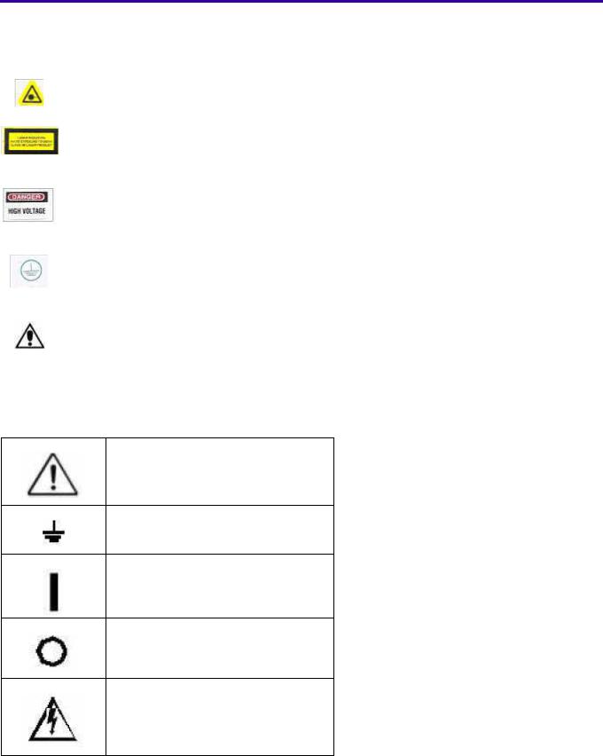
IEC Symbols Used
The system may have labels with one or more of the following symbols. These symbols indicate the IEC standards to which the system conforms.
Warning, Caution – consult accompanying documents
Protective ground points
Power ON
Power OFF
Caution – Electrical shock hazard
6H4866-02 |
13 |
Device-specific Safety Information
Safety Information |
|
Consignes de Sécurité |
|
LIFTING HAZARD |
DANGER POIDS LOURD |
||
The Kodak Point-of-Care 120/140 |
Le Scanner Kodak Point-of-Care 120/140 pèse 40 |
||
Scanner weighs 40 Kg (88lb). Do |
kg (88lb). N’essayez pas de porter le Scanner par |
||
not try to lift the Scanner by |
vous-même. Demandez toujours de l’aide d’une |
||
yourself. Always seek assistance |
autre personne. Porter un équipement trop lourd |
||
from another person. Lifting |
peut provoquer des dommages physiques et/ou |
||
equipment that is too heavy may |
endommager le matériel. |
||
result in injury to personnel and/or |
|
|
|
damage to the Scanner. |
|
|
|
|
|
||
WARNING |
ATTENTION |
||
The Kodak Point-of-Care 120/140 |
Le Scanner Kodak Point-of-Care 120/140 est un |
||
Scanner is a CLASS 1 Laser |
produit laser de la Classe 1. |
||
product. |
• |
Ne pas retirer le couvercle du Scanner. |
|
• |
Do not remove the Scanner |
• |
Le retrait du couvercle doit s’effectuer |
|
cover. |
||
|
|
uniquement par un personnel compétent. |
|
• |
Cover removal shall be done |
|
|
|
|
||
|
only by authorized service |
|
|
|
personnel! |
|
|
|
|
|
|
Regulatory Information
Introduction
This Product conforms to the following safety standards: IEC 601-1 Medical Electrical Equipment General Requirements for Safety, EN60601-1-2 Medical Electrical Equipment Electro-Magnetic Compatibility Requirements and Tests, IEC 60825-1 Safety of Laser Products.
This device complies with 21CFR 1040.10.
CE Conformity
This product conforms to the requirements of council directive 93/42/EEC. The Point-of-Care CR 120/140 is a Class I medical device. The Point-of-Care CR 120/140 bears the following mark of conformity.
The name and address of the CE representative appears on the back of the front page of this manual.
USA Regulations
The FDA cleared the system for sale in the USA.
 Caution
Federal US law restricts this device for sale by or on the order of a physician.
14 |
6H4866-02 |

System Description
Section 2: System Description
Introduction
Throughout this manual the Kodak Point-of-Care CR 120/140 Systems will be referred to as the Point-of-Care CR 120/140.
The Point-of-Care CR 120/140 is designed for the reading of phosphor x-ray screens (CR) by medical professionals. The system consists of the Point-of-Care CR 120/140 unit and the software package that includes:
•The Kodak QC software that operates the unit.
•An image viewing and archiving software package that supports the DICOM 3.1 standard and was approved by Carestream Health.
•The system features 8 x 10 in.; 10 x 12 in.; 14 x17 in.; 9.5 x 9.5 in. digital image reading and viewing archive.
Operational Principles
The Point-of-Care CR 120/140 is a digital imaging system for image acquisition and processing of static projection radiography that uses a phosphor screen with energy storage capability as an x-ray image receptor.
After exposure, a laser beam, which stimulates luminescence proportional to the local x-ray exposure, reads the screen. The luminescence signal is digitized. The data is then subjected to digital image processing.
The Point-of-Care CR 120/140 enables the user to read a screen quickly, and erase it to be ready for the next scan. The unit is compact and easy to use.
Using the Point-of-Care CR 120/140 enables medical professionals to “go digital” without changing their work practices or x-ray equipment.
System Overview
System Components
The Point-of-Care CR 120/140 consists of 17 major assemblies as well as sensors, which may be replaced in the field:
USB Board |
Erase Lamps Assembly |
Motion Board |
Erase Lamps Inverter Assembly |
Sensor Board |
Sensors: |
Photo Multiplier Assembly |
W0 Sensor |
Optic Head Assembly |
Z0 Sensor |
Roller Motor Assembly |
Rollers Sensor |
Linear Slide Assembly |
Screen Size Sensors |
Loader Stepper Motor Assembly |
R-Limit (Home) Sensor |
Key Assembly and Tray Assembly |
L-Limit Sensor |
Power Supply Assembly |
Loader Back Sensor |
Cassette Lock |
Cassette Present |
Auto-loop |
|
6H4866-02 |
15 |

Component Names and Descriptions
Part Name |
Description |
USB Board |
The USB Board receives operational commands from the host PC workstation via |
|
the USB port, and sends the commands to the appropriate Scanner component. It |
|
also transmits image data from the Scanner to the PC. |
|
|
Motion Board |
The Motion Board controls the Loader and Roller Motors and Erase Lamps. It reads |
|
the scanner sensors and passes the information to the USB Board. |
|
|
Linear Slide Assembly |
The Linear Slide Assembly moves the PM and the Optical Head Assemblies back and |
|
forth within the Drum. |
|
|
Optical Head Assembly |
The Optical Head Assembly includes the Laser Module and the Rotational Motor that |
|
rotates the Laser Tube and a mirror during scanning. The Laser Module’s beam |
|
illuminates the Phosphor screen and the mirror collects the light reflected from the |
|
phosphor screen and directs it to the Photo Multiplier. |
|
|
Photo Multiplier Tube |
The Photo Multiplier (PM) Tube collects the photons emitted from the screen. |
(PMT) |
|
|
|
Key Assembly and Tray |
These complementary assemblies guide the cassette into the scanner and secure it |
Assembly |
in position for the duration of the scanning process. The Auto-loop mechanism which |
|
is attached to the Key Assembly, controls the distance that the screen is returned |
|
into the cassette at the end of the process. |
|
|
Power Supply |
The AC/DC power supply provides DC power to the Scanner components. |
|
|
Loader Stepper Motor |
The Loader Stepper Motor Assembly extracts the phosphor screen from the cassette |
Assembly |
in preparation for insertion into the drum and assists in inserting the screen into the |
|
cassette. |
|
|
Roller Motor Assembly |
The Roller Motor Assembly pulls the phosphor screen from the cassette into the |
|
Drum. |
|
|
Erase Lamps Assembly |
The Erase Lamps Assembly brightly illuminates the phosphor screen after scanning, |
|
to erase the image so that the screen is ready to be used again. |
|
|
Erase Lamps Inverters |
The Erase Lamps Inverter Assembly converts the 15 VDC input to high voltage |
Assembly |
output to power the Erase Lamps. |
|
|
Sensor Board |
The Sensor Board is a through board used to connect the sensors to the Motion |
|
Board. |
|
|
Sensors |
|
|
The Erase Lamp Sensor detects an Erase Lamp failure. |
Eraser Lamps Sensor |
|
Left and Right Limit |
|
The Left and Right Limit Sensors indicate the end of travel of the Linear Assembly |
|
Sensors |
movement. |
Roller Sensor |
|
Detects when the screen enters and exits the Rollers. |
|
W0 Sensors Top and |
|
The W0 Sensor determines the activation and deactivation of the rollers according to |
|
Bottom |
screen presence at the entrance to the Drum. |
Z0 Sensor |
|
Detects the presence of the screen in the Drum. |
|
Screen Size Sensors |
|
There are four Screen Size Sensors that determine the size of the CR screen by the |
|
|
location of the screen guide that is positioned by the screen as it is inserted into the |
|
drum. |
15 x 30 Presence |
|
Installed in the Key Assembly, this Sensor detects the presence of a 15 x 30 in |
|
Sensor |
cassette adapter. |
|
|
16 |
6H4866-02 |

02-6H4866 |
|
|
2 |
|
|
|
3 |
|
|
4 |
|
5 |
|
ofDiagramBlock |
DiagramBlock |
1 |
|
|
|
|
|
|
|
|
|
|
|
||||
PC |
|
|
|
|
|
|
|
|
|
|
|
|
|
|
|
|
|
|
|
|
|
|
|
|
|
|
|
|
|
the |
of |
A |
|
|
|
|
|
|
|
J501 |
|
LED Panel |
Sensor |
|
A |
CRCare-of-Point |
120/140PoC |
|
|
|
|
|
|
|
|
|
|
|
|||||
|
|
|
|
|
|
|
|
|
|
|
|
|
|
|
|
|
|
|
|
|
|
|
|
J502 |
|
|
Sensor |
|
|
|
|
P1 |
|
|
|
|
|
|
|
|
|
|
|
|
|
|
|
|
|
|
|
|
|
Sensor |
. |
|
|
|
|
|
|
|
|
USB Board |
|
|
|
|
|
|
. |
|
|
|
|
||||
|
|
|
|
. |
|
|
|
|
|
|
|||||
|
|
|
|
Board |
. |
|
|
. |
|
|
|
|
|||
|
|
|
|
|
|
|
|
|
. |
|
|
|
|
||
|
|
|
|
|
|
|
|
|
|
|
|
|
|
||
|
|
|
|
|
|
|
|
J515 |
|
|
Sensor |
|
|
|
|
|
|
|
|
|
|
|
|
|
|
|
|
|
|
|
|
J300 |
|
J305 |
|
J304 |
|
|
|
J516 |
|
|
Sensor |
|
|
|
|
|
|
|
|
|
|
|
J500 |
|
|
|
|
|
|
|
|
|
|
|
|
|
|
|
|
|
|
|
|
|
|
|
|
|
|
CB090064 |
|
|
|
|
|
|
|
|
|
|
|
|
|
Power Supply |
|
|
U211 |
J200 |
|
|
|
|
|
|
|
|
|
120/140 |
|
+12V |
Power Supply |
|
|
|
|
|
|
|
|
|
|
||||
(Rotation Motor) |
+5V / +12V |
|
|
|
|
|
|
|
|
Power Supply |
|
|
|
||
B |
|
CB090064 |
|
|
|
|
|
|
|
+15V Lamps |
B |
|
|
||
|
|
|
|
|
|
|
|
|
(Motors+Lamps) |
|
|
|
|||
|
|
|
|
|
|
|
J208 |
J205 |
|
|
|
|
|
||
|
|
|
|
|
|
|
|
|
Group No. 1 |
|
|
|
|||
|
|
|
|
|
|
|
|
|
|
J211 |
|
|
|
|
|
|
|
|
|
|
|
|
Motion Board |
|
|
Power Supply |
|
|
|
||
|
|
|
J213 |
|
|
|
|
|
|
|
|
|
|
||
|
|
|
|
|
|
|
|
|
|
+15V |
|
|
|
||
|
|
|
|
|
|
|
|
|
|
|
|
|
|
||
|
|
|
J203 |
J206 |
|
J201 |
J204 |
J212 |
J202 |
|
Group No. 2 |
|
|
|
|
|
|
|
|
|
|
|
|
|
|
||||||
J1 |
|
|
J401 |
DC |
|
SM |
SM |
|
J2 |
J4 |
|
|
|
|
|
|
|
|
|
|
|
|
Inverters |
|
|
|
|
||||
|
Carrier - Laser |
|
|
|
|
|
|
J5 |
|
|
|
|
|||
C |
|
|
|
|
|
|
Group |
|
C |
|
|
||||
PM Board |
|
|
|
|
|
Lamps Board |
|
|
|
|
|||||
J403 |
J404 |
J402 |
Roller |
Linear |
Load/Unload |
|
No. 2 |
|
|
|
|
||||
|
Motor |
|
|
|
|
|
|
|
|
|
|
|
|||
|
|
|
|
|
|
|
|
|
J3 |
|
|
|
|
|
|
|
|
|
|
|
|
|
|
|
J1 |
|
|
|
|
|
|
|
|
|
|
|
|
|
|
|
|
Inverters |
|
|
|
|
|
|
|
|
|
|
|
|
|
|
|
|
|
|
|
|
|
|
|
|
|
|
|
|
|
|
|
|
Group |
|
|
|
|
|
|
|
|
|
|
|
|
|
|
|
No. 1 |
|
|
|
|
|
|
Encoder |
Rotation Driver |
Rotation |
|
|
|
|
|
|
LAMPx8 |
LAMPx6 |
|
|
|
|
Laser |
Motor |
|
|
|
|
|
LP1-8 |
LP9-14 |
|
|
|
|||
|
|
|
|
|
|
|
Solenoid |
|
|
|
|
|
|
|
|
|
|
|
|
|
|
|
|
|
|
|
Lamp Sensors |
|
|
|
|
D |
|
|
|
|
|
|
|
|
|
|
Board |
|
D |
|
|
1 |
|
|
2 |
|
|
|
3 |
|
|
4 |
|
5 |
|
|
System |
|
|
|
|
|
|
|
|
|
|
Description |
|||||
17 |
|
|
|
|
|
|
|
|
|
|
|
|
|
|
|

Views of PoC 120/140
Scanner Front View
Motor Driver
Linear Slide Assembly
 Laser Board
Inverters
LED Panel
Scanner Rear View
Sensor Board
Erase Lamp
Fuses
Loader
Stepper Motor
On/Off
Switch
Motion Board |
USB Board |
Power Cord
Socket
18 |
6H4866-02 |

System Description
Scanner Left View
Linear
Motor
Erase Lamp
Roller
Sensor
Roller
Motor
Inverters
Scanner Right View
Laser Unit
Power Supply
Unit
6H4866-02 |
19 |

Component Description
USB Board
The USB Board receives operational commands from the host PC workstation via the USB port, and sends the commands to the appropriate Unit component. It also transmits image data from the Unit to the PC.
USB Board
1 4 5
6
2
3
USB Board Connections
Connector |
|
Destination |
|
|
|
Connector 1 J7 |
5 V/12 V Power Supply |
|
|||
|
|
|
|
|
|
|
|
Pin 1 |
White |
|
5 V |
|
|
|
|
|
|
|
|
Pin 2 |
Brown |
|
GND |
|
|
|
|
|
|
|
|
Pin 4 |
Green |
|
12 V |
|
|
|
|
|
|
Connector 2 J3 |
Flat cable to J1 on PM Board |
|
|||
|
|
|
|||
Connector 3 J1 |
Flex cable to J200 on Motion Board |
|
|||
|
|
|
|
||
Connector 4 |
J11 |
Barcode Connection |
|
||
|
|
|
|
|
|
|
|
Pin 1 |
Red |
|
5V |
|
|
|
|
|
|
|
|
Pin 2 |
Black |
|
Gnd |
|
|
|
|
|
|
Connector 5 |
J6 |
Not in use |
|
|
|
|
|
|
|
||
Connector 6 |
J4 |
Barcode Connection |
|
||
|
|
|
|
|
|
|
|
Pin 1 |
Purple |
|
Signal |
|
|
|
|
|
|
|
|
Pin 2 |
Brown |
|
Signal |
|
|
|
|
|
|
20 |
6H4866-02 |
System Description
Motion Board
The Motion Board has the following functions:
•Controls the Loader and Roller Motors
•Controls the Erase Lamps
•Reads the Unit sensors and passes the information to the USB Board
Motion Board
|
|
|
|
1 |
|
|
|
|
|
|
|
|
2 |
|
|
|
|
|
|
|
|
4 |
7 |
|
|
|
|
|
|
|
|
|
|
||
|
|
|
|
5 |
|
|
|
|
|
|
|
|
6 |
8 |
|
|
|
|
|
|
|
|
|
|
|
|
|
|
|
|
9 |
12 |
|
|
|
|
|
|
|
10 |
|
|
||
|
|
11 |
|
|
|
|
||
Motion Board Connections |
|
|
|
|
|
|
|
|
|
|
|
|
|
|
|
|
|
|
Connector |
Destination |
|
|
|
|
||
|
|
|
|
|||||
|
Connector 1 J206 |
Connectors Panel (Rollers Motor) |
||||||
|
|
|
|
|
|
|
|
|
|
|
Pin 1 |
|
|
orange |
|
12 V |
|
|
|
|
|
|
|
|
|
|
|
|
Pin 2 |
|
|
pink |
|
GND |
|
|
|
|
|
|
|
|
||
|
|
|
Rollers forward |
+12 V |
|
|
||
|
|
|
Rollers backwards -12 V |
|
|
|||
|
|
|
Rollers stop 0 V |
|
|
|||
|
|
|
|
|||||
|
Connector 2 J212 |
J212 on the Auto-loop Assembly |
||||||
|
|
|
|
|
|
|||
|
Connector 3 J213 |
12 V Power Supply |
|
|
||||
|
|
|
|
|
|
|
|
|
|
|
Pin 1 |
|
|
red |
|
12 V |
|
|
|
|
|
|
|
|
||
|
Connector 4 J205 |
J1 on Front Panel LED Board |
|
|
||||
|
|
|
|
|
|
|||
|
Connector 5 J203 |
J401 on Laser Board |
|
|
||||
|
|
|
|
|
|
|||
|
Connector 6 J208 |
J500 on Sensor Board |
|
|
||||
|
|
|
|
|||||
|
Connector 7 J202 |
J2 on Erase Lamps Inverters Assembly |
||||||
|
|
|
|
|
|
|
|
|
|
Connector 8 J204 |
Loader carrier |
|
|
|
|
||
|
|
|
|
|
|
|
|
|
|
|
Orange + blue |
|
130 Hz |
load/unload |
|||
|
|
|
|
|
|
|
||
|
|
Red + yellow |
|
130 Hz |
load/unload |
|||
|
|
|
|
|
|
|
|
|
|
Connector 9 J201 |
Stepper Motor |
|
|
|
|
||
|
|
|
|
|
|
|
||
|
|
Yellow + green |
|
11 KHz moving left/right; 0 KHz stop |
||||
|
|
|
|
|
|
|||
|
|
Brown+ white |
|
11 KHz moving left/right; 0 KHz stop |
||||
|
|
|
|
|
|
|
||
|
Connector 10 J211 |
15 V Power Supply |
|
|
|
|||
|
|
|
|
|
|
|
|
|
|
|
Pin 1 |
|
|
black 1 |
|
GND |
|
|
|
|
|
|
|
|
|
|
|
|
Pin 2 |
|
|
black 2 |
|
15 V |
|
|
|
|
|
|
|
|
||
|
Connector 11 J215 |
5 V Power Supply |
|
|
|
|||
|
|
|
|
|
|
|
|
|
|
|
Pin 1 |
|
|
brown |
|
GND |
|
|
|
|
|
|
|
|
|
|
|
|
Pin 2 |
|
|
white |
|
5 V |
|
|
|
|
|
|
|
|
||
|
Connector 12 |
J302 on USB Board |
|
|
|
|||
|
|
|
|
|
|
|
|
|
6H4866-02 |
21 |
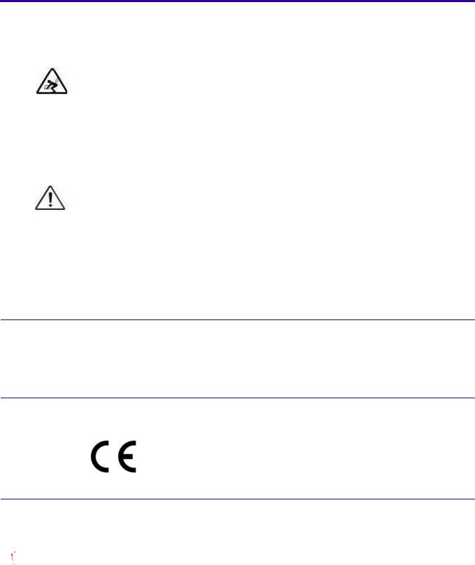
Sensor Board
Sensor Board Connections
The Sensor Board is a through board used to connect the sensors to the Motion Board.
Sensor Board
Sensor Board Connections
|
J513 |
J514 |
J515 |
J516 |
|
Cassette |
Cassette Lock |
Right Limit Sensor |
Left Limit Sensor |
|
Presence Sensor |
Sensor |
|
|
|
|
|
|
|
|
J509 |
J510 |
J511 |
J512 15 x 30 |
|
Roller Sensor |
|
W0 Sensor |
Cassette Sensor |
|
|
|
|
|
|
J505 |
J506 |
J507 |
J508 |
|
Sensor 1 on the |
Sensor 2 on the |
Sensor 3 on the |
Loader Sensor in |
|
Drum |
Drum |
Drum |
Back Position |
|
|
|
|
|
|
J501 |
J502 |
J503 |
J504 Auto-loop |
|
Sensor 4 on the |
Sensor 5 on the |
|
Sensor |
|
Drum |
Drum |
|
|
|
|
|
|
|
J500 |
|
|
|
|
To J208 on Motion |
|
|
|
|
Board |
|
|
|
|
|
|
|
|
|
22 |
6H4866-02 |

System Description
Typical Sensor Connections
|
Connector |
|
|
|
Sensor |
|
||||
|
|
|
|
|
|
|
||||
1 |
|
2 |
3 |
4 |
|
|
|
|
|
|
|
|
|
|
|||||||
(Brown) |
|
(White) |
(Blue) |
Not in |
|
|
|
|
|
|
5 V |
|
Signal |
GND |
use |
|
|
|
|
|
|
|
|
|
|
|
||||||
|
|
|
|
|
|
|
|
|
|
|
Sensor Wiring Colors
Sensor |
Wire No. |
Wire Color |
Signal |
|
Sensor On |
1 |
Brown |
5 |
V always |
(Flag in Sensor) |
|
|
|
|
2 |
White |
0 |
V |
|
|
|
|
|
|
|
3 |
Blue |
GND always |
|
|
|
|
|
|
|
4 |
Not in use |
|
|
|
|
|
|
|
Sensor Off |
1 |
Brown |
5 |
V always |
(Flag not in sensor) |
|
|
|
|
2 |
White |
5 |
V |
|
|
|
|
|
|
|
3 |
Blue |
GND always |
|
|
|
|
|
|
|
4 |
Not in use |
|
|
|
|
|
|
|
Measuring voltage:
1.All sensors except J511: measure between pin 2 & 3 and insert object between sensors.
2.For J511 only: measure between pin 2 & pin 3 and insert a screen to system. The voltage should be between 4.5 - 5 V.
6H4866-02 |
23 |

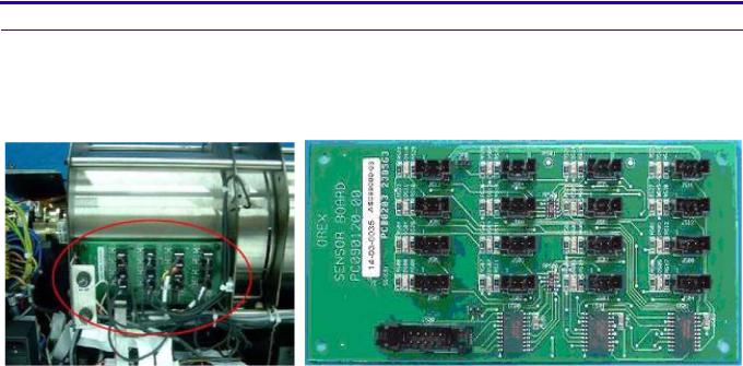
PM Assembly
The Photo Multiplier (PM) Tube collects the photons emitted from the screen.
PM and PM Board
24 |
6H4866-02 |
System Description
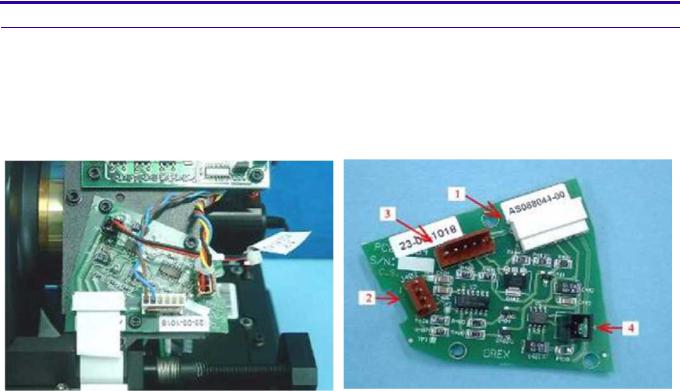
Optical Head Assembly
The Optical Head Assembly includes the Laser Module and the Rotational Motor that rotates the Laser Tube and a mirror during scanning. The Laser Module’s beam illuminates the Phosphor screen and the mirror collects the light reflected from the phosphor screen and directs it to the Photo Multiplier.
Laser Board
Laser Board
Laser Board Connections
Connector |
Destination |
|
|
|
1 |
J401 on Motion Board CB080008 |
|
|
|
|
|
|
|
|
2 |
J402 Encoder Reader CB090014 |
|
|
|
|
|
|
|
|
|
Pin 1 |
Red |
GND |
|
|
|
|
|
|
|
Pin 2 |
Black |
Index |
41 ±0.5 Hz |
|
|
|
|
|
|
Pin 3 |
Blue |
Encoder |
41 ± 0.5 KHz |
|
|
|
|
|
|
Pin 4 |
Yellow |
5 V |
|
|
|
|
|
|
3 |
J403 Rotation Motor |
Board CB090040 |
|
|
|
|
|
|
|
|
Pin 1 |
Blue |
GND |
|
|
|
|
|
|
|
Pin 2 |
Brown |
12 V Rotation Motor - On |
|
|
|
|
|
|
4 |
J404 Laser Assembly |
CB090029 |
|
|
|
|
|
|
|
|
Pin 1 |
Red |
Laser On 3.3 V |
|
|
|
|
|
|
|
Pin 2 |
Black |
GND |
|
|
|
|
|
|
Laser Tube
The Laser Tube emits the light to energize the phosphorus screen.
6H4866-02 |
25 |

Laser
26 |
6H4866-02 |

System Description
Roller Motor Assembly
The Roller Motor Assembly pulls the phosphor screen from the Cassette into the Drum.
Roller Motor
Roller Motor Connector
 Note
Note
Measure the voltage when the rollers are turning at full speed.
Roller Motor Connector
Connector Panel to the Roller Motor
Pin 1 |
Orange |
Rollers forward +15V |
|
|
Rollers backwards -15 V |
|
|
Rollers stop 0 V |
|
|
|
Pin 2 |
Brown |
GND |
|
|
|
6H4866-02 |
27 |
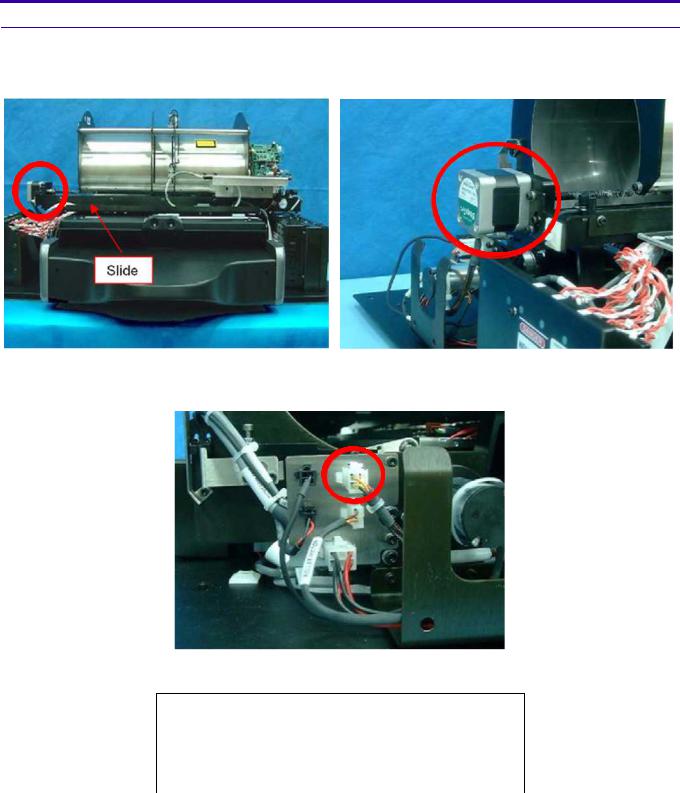
Linear Slide Assembly
The Linear Slide Assembly moves the PM and the Laser within the Drum to read the Phosphor Screen.
Linear Slide Assembly
Linear Slide Stepper Motor Connector
Slide Stepper Motor Connector
Connector Panel to the Slide Stepper Motor CB 090077
Pin 1 |
White |
Phase A |
Pin 2 |
Orange |
Phase A |
|
|
|
Pin 3 |
Yellow |
Phase B |
|
|
|
Pin 4 |
Black |
Phase B |
|
|
|
28 |
6H4866-02 |

System Description
Loader Stepper Motor Assembly
The Loader Stepper Motor Assembly operates the mechanism which extracts the phosphor screen from the cassette and assists in inserting the screen into the cassette.
Carriage Stepper Motor
Carriage Stepper Motor Wiring
Loader Stepper Motor Wiring
J204 on Motion Board
Orange + blue |
130 Hz load/unload |
Red + yellow |
130 Hz load/unload |
|
|
Black + white |
not in use |
|
|
6H4866-02 |
29 |
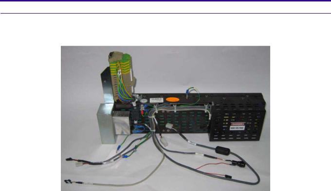
Power Supply Assembly
The AC/DC Power Supply provides DC power to the components of the unit.
Power Supply Assembly
Power Supply Connectors
Pin |
|
|
|
|
Number |
System Type |
Destination |
Function |
|
|
|
|
|
|
|
ACL2/4 |
PoC120/140 |
|
|
|
|
|
|
|
|
Source: AC |
INPUT POWER |
|
|
|
|
|
|
|
|
CB090065 |
CB090137 |
J211 on Motion Board |
|
|
|
|
|
|
Pin 1 |
Red |
Black 1 |
|
15 V |
|
|
|
|
|
Pin 2 |
|
Black 2 |
|
GND 0 V |
|
|
|
|
|
|
CB090071 |
CB 090141_a |
J213 on Motion Board |
|
|
|
|
|
|
Pin 1 |
|
Black 1 |
|
12 V |
|
|
|
|
|
|
CB090064 |
CB090136-a |
J215 on Motion Board |
|
|
|
|
|
|
Pin 3 |
Red |
Brown |
|
5 V |
|
|
|
|
|
Pin 5 |
Black |
White |
|
GND 0 V |
|
|
|
|
|
|
CB090064 |
CB 090064_b |
J305 on USB Board |
|
|
|
|
(power input) |
|
|
|
|
|
|
Pin 1 |
Red |
White |
|
12 V |
|
|
|
|
|
Pin 2 |
Black |
Brown |
|
5 V |
|
|
|
|
|
Pin 4 |
White |
Green |
|
GND 0 V |
|
|
|
|
|
|
CB090065 |
CB 090065_b |
Fuses Connector |
|
|
|
|
|
|
Pin 1 |
Red |
Black 1 |
|
15 V |
|
|
|
|
|
Pin 2 |
Black |
Black 3 |
|
GND |
|
|
|
|
|
Pin 3 |
White |
Black 2 |
|
15 V |
|
|
|
|
|
Pin 4 |
Green |
Black 4 |
|
GND 0 V |
|
|
|
|
|
30 |
6H4866-02 |
Loading...