


 Loading...
{IllustratedPartsList}{Production}{Carestream Health Inc.}{None}
Publication No. 6H4869
17MAR2010 Supersedes 6H4869-01 23DEC09
Service Manual
for the
KODAK Point-of-Care CR 360 System
 Important
•Qualified service personnel must install this modification.
•See the Service Portal for possible updates before doing this modification.
•When doing the procedures in this document, you must use safe work practices and wear the correct personal protective equipment (for example, safety eyewear) according to your company’s standard operating procedures.
None
© CARESTREAM HEALTH, INC. 2010

Service Guide
KODAK Point-of-Care CR 360 System Service Manual
Publication Number: 6H4869
© Carestream Health, Inc., 2010
US FEDERAL LAW RESTRICTS THIS DEVICE TO SALE BY OR ON THE ORDER OF A PHYSICIAN ONLY.
All rights reserved. No part of this manual may be reproduced or copied in any form by any means–graphic, electronic or mechanical, including photocopying, typing, or information retrieval systems–without written permission of Carestream Health, Inc.
Use of Manual
The KODAK Point-of-Care CR 360 System is designed to meet international safety and performance standards. Personnel operating the unit must have a thorough understanding of the proper operation of the system. This manual has been prepared to aid medical and technical personnel to understand and operate the system. Do not operate the system before reading this manual and gaining a clear understanding of the operation of the system. If any part of this manual is not clear, please contact your Carestream Health representative for clarification.
Authorized European Representative
Carestream Health France
LES MERCURIALES
40, rue Jean Jaures
93176 BAGNOLET CEDEX
France
The Kodak trademark and trade dress are used under license from Kodak.
Carestream Health, Inc.
150 Verona Street
Rochester, NY 14608
2 |
6H4869 |

Table of Contents |
|
Description |
Page |
Safety and Regulatory Information . . . . . . . . . . . . . . . . . . . . . . . . . . . . . . . . . . . . . . . . . . . |
9 |
Introduction . . . . . . . . . . . . . . . . . . . . . . . . . . . . . . . . . . . . . . . . . . . . . . . . . . . . . . . . . |
9 |
General Safety Guidelines . . . . . . . . . . . . . . . . . . . . . . . . . . . . . . . . . . . . . . . . . . . . . |
9 |
Electrical Hazards. . . . . . . . . . . . . . . . . . . . . . . . . . . . . . . . . . . . . . . . . . . . . . . . . . . . |
10 |
Explosion and Implosion Hazards . . . . . . . . . . . . . . . . . . . . . . . . . . . . . . . . . . . . . . . |
10 |
Overheating . . . . . . . . . . . . . . . . . . . . . . . . . . . . . . . . . . . . . . . . . . . . . . . . . . . . . . . . |
10 |
Laser Safety Instructions . . . . . . . . . . . . . . . . . . . . . . . . . . . . . . . . . . . . . . . . . . . . . . |
10 |
Recycling the Unit. . . . . . . . . . . . . . . . . . . . . . . . . . . . . . . . . . . . . . . . . . . . . . . . . . . . |
11 |
Labelling Summary . . . . . . . . . . . . . . . . . . . . . . . . . . . . . . . . . . . . . . . . . . . . . . . . . . . |
11 |
IEC Symbols Used . . . . . . . . . . . . . . . . . . . . . . . . . . . . . . . . . . . . . . . . . . . . . . . . . . . |
11 |
Device-specific Safety Information . . . . . . . . . . . . . . . . . . . . . . . . . . . . . . . . . . . . . . . |
12 |
Regulatory Information . . . . . . . . . . . . . . . . . . . . . . . . . . . . . . . . . . . . . . . . . . . . . . . . |
12 |
Introduction . . . . . . . . . . . . . . . . . . . . . . . . . . . . . . . . . . . . . . . . . . . . . . . . . . . . . |
12 |
CE Conformity . . . . . . . . . . . . . . . . . . . . . . . . . . . . . . . . . . . . . . . . . . . . . . . . . . |
12 |
USA Regulations . . . . . . . . . . . . . . . . . . . . . . . . . . . . . . . . . . . . . . . . . . . . . . . . |
12 |
System Description. . . . . . . . . . . . . . . . . . . . . . . . . . . . . . . . . . . . . . . . . . . . . . . . . . . . . . . |
13 |
Introduction . . . . . . . . . . . . . . . . . . . . . . . . . . . . . . . . . . . . . . . . . . . . . . . . . . . . . . . . . |
13 |
Operational Principles. . . . . . . . . . . . . . . . . . . . . . . . . . . . . . . . . . . . . . . . . . . . . . . . . |
13 |
System Overview . . . . . . . . . . . . . . . . . . . . . . . . . . . . . . . . . . . . . . . . . . . . . . . . . . . . |
14 |
Component Names and Descriptions . . . . . . . . . . . . . . . . . . . . . . . . . . . . . . . . . |
14 |
Views of the Point-of-Care CR 360. . . . . . . . . . . . . . . . . . . . . . . . . . . . . . . . . . . |
16 |
Component Description . . . . . . . . . . . . . . . . . . . . . . . . . . . . . . . . . . . . . . . . . . . . . . . |
18 |
Power Line Filter Module . . . . . . . . . . . . . . . . . . . . . . . . . . . . . . . . . . . . . . . . . . |
18 |
IMCS Board . . . . . . . . . . . . . . . . . . . . . . . . . . . . . . . . . . . . . . . . . . . . . . . . . . . . |
18 |
Linear Slide Assembly . . . . . . . . . . . . . . . . . . . . . . . . . . . . . . . . . . . . . . . . . . . . |
19 |
Overview . . . . . . . . . . . . . . . . . . . . . . . . . . . . . . . . . . . . . . . . . . . . . . . . . . . |
19 |
Two Types of Linear Screws. . . . . . . . . . . . . . . . . . . . . . . . . . . . . . . . . . . . |
19 |
Linear Motor . . . . . . . . . . . . . . . . . . . . . . . . . . . . . . . . . . . . . . . . . . . . . . . . . . . . |
20 |
Optical Head Assembly . . . . . . . . . . . . . . . . . . . . . . . . . . . . . . . . . . . . . . . . . . . |
20 |
Photo Multiplier Assembly (PM) . . . . . . . . . . . . . . . . . . . . . . . . . . . . . . . . . . . . . |
21 |
Loader Stepper Assembly . . . . . . . . . . . . . . . . . . . . . . . . . . . . . . . . . . . . . . . . . |
22 |
Roller Drive Motor Assembly . . . . . . . . . . . . . . . . . . . . . . . . . . . . . . . . . . . . . . . |
22 |
Right and Left Limit Sensors. . . . . . . . . . . . . . . . . . . . . . . . . . . . . . . . . . . . . . . . |
23 |
Service Procedures . . . . . . . . . . . . . . . . . . . . . . . . . . . . . . . . . . . . . . . . . . . . . . . . . . . . . . |
24 |
Service Tools . . . . . . . . . . . . . . . . . . . . . . . . . . . . . . . . . . . . . . . . . . . . . . . . . . . . . . . |
24 |
Removing the Scanner Cover. . . . . . . . . . . . . . . . . . . . . . . . . . . . . . . . . . . . . . . . . . . |
25 |
Installing the Scanner Cover. . . . . . . . . . . . . . . . . . . . . . . . . . . . . . . . . . . . . . . . . . . . |
25 |
Activating the Scanner Without the Cover . . . . . . . . . . . . . . . . . . . . . . . . . . . . . . . . . |
26 |
Activation Procedures. . . . . . . . . . . . . . . . . . . . . . . . . . . . . . . . . . . . . . . . . . . . . |
26 |
Activating the Scanner Without the Cover (Laser Deactivated) . . . . . . . . . . . . . |
26 |
Before Service Operations . . . . . . . . . . . . . . . . . . . . . . . . . . . . . . . . . . . . . |
26 |
After Service Operations. . . . . . . . . . . . . . . . . . . . . . . . . . . . . . . . . . . . . . . |
27 |
Activating the Scanner without the Cover (Laser Activated). . . . . . . . . . . . . . . . |
27 |
Before Service Operations . . . . . . . . . . . . . . . . . . . . . . . . . . . . . . . . . . . . . |
27 |
After Service Operations. . . . . . . . . . . . . . . . . . . . . . . . . . . . . . . . . . . . . . . |
27 |
Replacing the Power Line Filter Module . . . . . . . . . . . . . . . . . . . . . . . . . . . . . . . . . . . |
28 |
Tools Required . . . . . . . . . . . . . . . . . . . . . . . . . . . . . . . . . . . . . . . . . . . . . . . . . . |
28 |
Removing the Power Line Filter Module. . . . . . . . . . . . . . . . . . . . . . . . . . . . . . . |
28 |
Installing the Power Line Filter Module. . . . . . . . . . . . . . . . . . . . . . . . . . . . . . . . |
29 |
Replacing the Fuses . . . . . . . . . . . . . . . . . . . . . . . . . . . . . . . . . . . . . . . . . . . . . . . . . . |
30 |
Tools Required . . . . . . . . . . . . . . . . . . . . . . . . . . . . . . . . . . . . . . . . . . . . . . . . . . |
30 |
Procedure . . . . . . . . . . . . . . . . . . . . . . . . . . . . . . . . . . . . . . . . . . . . . . . . . . . . . . |
30 |
Replacing the Controller Board. . . . . . . . . . . . . . . . . . . . . . . . . . . . . . . . . . . . . . . . . . |
32 |
Tools Required . . . . . . . . . . . . . . . . . . . . . . . . . . . . . . . . . . . . . . . . . . . . . . . . . . |
32 |
6H4869 |
3 |

Service Guide
Removing the Controller Board . . . . . . . . . . . . . . . . . . . . . . . . . . . . . . . . . . . . . |
32 |
Installing the Controller Board . . . . . . . . . . . . . . . . . . . . . . . . . . . . . . . . . . . . . . |
34 |
Replacing the IMCS Board. . . . . . . . . . . . . . . . . . . . . . . . . . . . . . . . . . . . . . . . . . . . . |
36 |
Tools Required . . . . . . . . . . . . . . . . . . . . . . . . . . . . . . . . . . . . . . . . . . . . . . . . . . |
36 |
Removing the IMCS Board. . . . . . . . . . . . . . . . . . . . . . . . . . . . . . . . . . . . . . . . . |
36 |
Separating the Sensor Board from the Motion Board . . . . . . . . . . . . . . . . . . . . |
37 |
Installing the IMCS Board. . . . . . . . . . . . . . . . . . . . . . . . . . . . . . . . . . . . . . . . . . |
38 |
Replacing the Photo Multiplier Board. . . . . . . . . . . . . . . . . . . . . . . . . . . . . . . . . . . . . |
39 |
Tools Required . . . . . . . . . . . . . . . . . . . . . . . . . . . . . . . . . . . . . . . . . . . . . . . . . . |
39 |
Removing the PM Board . . . . . . . . . . . . . . . . . . . . . . . . . . . . . . . . . . . . . . . . . . |
39 |
Installing the PM Board . . . . . . . . . . . . . . . . . . . . . . . . . . . . . . . . . . . . . . . . . . . |
40 |
Replacing the Photo Multiplier Assembly. . . . . . . . . . . . . . . . . . . . . . . . . . . . . . . . . . |
41 |
Tools Required . . . . . . . . . . . . . . . . . . . . . . . . . . . . . . . . . . . . . . . . . . . . . . . . . . |
41 |
Removing the PM Tube . . . . . . . . . . . . . . . . . . . . . . . . . . . . . . . . . . . . . . . . . . . |
41 |
Installing the PM Tube . . . . . . . . . . . . . . . . . . . . . . . . . . . . . . . . . . . . . . . . . . . . |
43 |
Replacing the Optical Head Assembly. . . . . . . . . . . . . . . . . . . . . . . . . . . . . . . . . . . . |
45 |
Tools Required . . . . . . . . . . . . . . . . . . . . . . . . . . . . . . . . . . . . . . . . . . . . . . . . . . |
45 |
Removing the Optical Head Assembly. . . . . . . . . . . . . . . . . . . . . . . . . . . . . . . . |
45 |
Installing the Optical Head Assembly. . . . . . . . . . . . . . . . . . . . . . . . . . . . . . . . . |
46 |
Replacing the Linear Screw Type A. . . . . . . . . . . . . . . . . . . . . . . . . . . . . . . . . . . . . . |
48 |
Tools Required . . . . . . . . . . . . . . . . . . . . . . . . . . . . . . . . . . . . . . . . . . . . . . . . . . |
48 |
Removing the Linear Screw Type A. . . . . . . . . . . . . . . . . . . . . . . . . . . . . . . . . . |
48 |
Installing the Linear Screw Type A. . . . . . . . . . . . . . . . . . . . . . . . . . . . . . . . . . . |
49 |
Replacing the Linear Screw Type B. . . . . . . . . . . . . . . . . . . . . . . . . . . . . . . . . . . . . . |
50 |
Tools Required . . . . . . . . . . . . . . . . . . . . . . . . . . . . . . . . . . . . . . . . . . . . . . . . . . |
50 |
Removing the Linear Screw Type B. . . . . . . . . . . . . . . . . . . . . . . . . . . . . . . . . . |
50 |
Installing the Linear Screw Type B. . . . . . . . . . . . . . . . . . . . . . . . . . . . . . . . . . . |
52 |
Test Procedure. . . . . . . . . . . . . . . . . . . . . . . . . . . . . . . . . . . . . . . . . . . . . . . . . . |
53 |
Replacing the Linear Motor Type A . . . . . . . . . . . . . . . . . . . . . . . . . . . . . . . . . . . . . . |
54 |
Tools Required . . . . . . . . . . . . . . . . . . . . . . . . . . . . . . . . . . . . . . . . . . . . . . . . . . |
54 |
Removing the Linear Motor Type A . . . . . . . . . . . . . . . . . . . . . . . . . . . . . . . . . . |
54 |
Installing the Linear Motor Type A . . . . . . . . . . . . . . . . . . . . . . . . . . . . . . . . . . . |
56 |
Replacing the Linear Motor Type B . . . . . . . . . . . . . . . . . . . . . . . . . . . . . . . . . . . . . . |
58 |
Tools Required . . . . . . . . . . . . . . . . . . . . . . . . . . . . . . . . . . . . . . . . . . . . . . . . . . |
58 |
Removing Type B Linear Motor . . . . . . . . . . . . . . . . . . . . . . . . . . . . . . . . . . . . . |
58 |
Installing the Linear Motor Type B . . . . . . . . . . . . . . . . . . . . . . . . . . . . . . . . . . . |
61 |
Replacing the Roller Drive Motor Assembly. . . . . . . . . . . . . . . . . . . . . . . . . . . . . . . . |
64 |
Tools Required . . . . . . . . . . . . . . . . . . . . . . . . . . . . . . . . . . . . . . . . . . . . . . . . . . |
64 |
Removing the Drive Roller Motor Assembly. . . . . . . . . . . . . . . . . . . . . . . . . . . . |
64 |
Installing the Roller Drive Motor . . . . . . . . . . . . . . . . . . . . . . . . . . . . . . . . . . . . . |
65 |
Replacing the Loader Stepper Assembly. . . . . . . . . . . . . . . . . . . . . . . . . . . . . . . . . . |
67 |
Tools Required . . . . . . . . . . . . . . . . . . . . . . . . . . . . . . . . . . . . . . . . . . . . . . . . . . |
67 |
Removing the Loader Stepper Assembly. . . . . . . . . . . . . . . . . . . . . . . . . . . . . . |
67 |
Installing the Loader Stepper Assembly. . . . . . . . . . . . . . . . . . . . . . . . . . . . . . . |
67 |
Replacing the Laser Board. . . . . . . . . . . . . . . . . . . . . . . . . . . . . . . . . . . . . . . . . . . . . |
69 |
Tools Required . . . . . . . . . . . . . . . . . . . . . . . . . . . . . . . . . . . . . . . . . . . . . . . . . . |
69 |
Removing the Laser Board. . . . . . . . . . . . . . . . . . . . . . . . . . . . . . . . . . . . . . . . . |
69 |
Installing the Laser Board. . . . . . . . . . . . . . . . . . . . . . . . . . . . . . . . . . . . . . . . . . |
70 |
Replacing the Power Supply . . . . . . . . . . . . . . . . . . . . . . . . . . . . . . . . . . . . . . . . . . . |
71 |
Tools Required . . . . . . . . . . . . . . . . . . . . . . . . . . . . . . . . . . . . . . . . . . . . . . . . . . |
71 |
Removing the Power Supply Unit. . . . . . . . . . . . . . . . . . . . . . . . . . . . . . . . . . . . |
71 |
Installing the Power Supply Unit. . . . . . . . . . . . . . . . . . . . . . . . . . . . . . . . . . . . . |
75 |
Replacing the Erase Lamps Assembly . . . . . . . . . . . . . . . . . . . . . . . . . . . . . . . . . . . |
77 |
Tools Required . . . . . . . . . . . . . . . . . . . . . . . . . . . . . . . . . . . . . . . . . . . . . . . . . . |
77 |
Removing the Erase Lamps Assembly . . . . . . . . . . . . . . . . . . . . . . . . . . . . . . . |
77 |
Installing the Erase Lamps Assembly . . . . . . . . . . . . . . . . . . . . . . . . . . . . . . . . |
78 |
Replacing the Erase Lamps Fuse . . . . . . . . . . . . . . . . . . . . . . . . . . . . . . . . . . . . . . . |
80 |
Tools Required . . . . . . . . . . . . . . . . . . . . . . . . . . . . . . . . . . . . . . . . . . . . . . . . . . |
80 |
Installing the Erase Lamps Fuse . . . . . . . . . . . . . . . . . . . . . . . . . . . . . . . . . . . . |
80 |
4 |
6H4869 |

Test Procedure . . . . . . . . . . . . . . . . . . . . . . . . . . . . . . . . . . . . . . . . . . . . . . . . . . |
80 |
Replacing the Erase Lamp Board. . . . . . . . . . . . . . . . . . . . . . . . . . . . . . . . . . . . . . . . |
81 |
Tools Required . . . . . . . . . . . . . . . . . . . . . . . . . . . . . . . . . . . . . . . . . . . . . . . . . . |
81 |
Removing the Erase Lamp Board. . . . . . . . . . . . . . . . . . . . . . . . . . . . . . . . . . . . |
81 |
Installing the Erase Lamp Board. . . . . . . . . . . . . . . . . . . . . . . . . . . . . . . . . . . . . |
81 |
Replacing the Erase Lamps Inverter Board . . . . . . . . . . . . . . . . . . . . . . . . . . . . . . . . |
82 |
Tools Required . . . . . . . . . . . . . . . . . . . . . . . . . . . . . . . . . . . . . . . . . . . . . . . . . . |
82 |
Removing the Erase Lamps Inverter Board . . . . . . . . . . . . . . . . . . . . . . . . . . . . |
82 |
Installing the Erase Lamps Inverter Board . . . . . . . . . . . . . . . . . . . . . . . . . . . . . |
82 |
Replacing the Roof Assembly and Tray Assembly. . . . . . . . . . . . . . . . . . . . . . . . . . . |
83 |
Introduction . . . . . . . . . . . . . . . . . . . . . . . . . . . . . . . . . . . . . . . . . . . . . . . . . . . . . |
83 |
Tools Required . . . . . . . . . . . . . . . . . . . . . . . . . . . . . . . . . . . . . . . . . . . . . . . . . . |
83 |
Removing the Roof Assembly . . . . . . . . . . . . . . . . . . . . . . . . . . . . . . . . . . . . . . |
83 |
Removing the Tray Assembly. . . . . . . . . . . . . . . . . . . . . . . . . . . . . . . . . . . . . . . |
85 |
Installing the Tray Assembly and the Roof Assembly. . . . . . . . . . . . . . . . . . . . . |
86 |
Test Procedure . . . . . . . . . . . . . . . . . . . . . . . . . . . . . . . . . . . . . . . . . . . . . . . . . . |
87 |
Replacing the Right and Left Limit Sensors . . . . . . . . . . . . . . . . . . . . . . . . . . . . . . . . |
88 |
Tools Required . . . . . . . . . . . . . . . . . . . . . . . . . . . . . . . . . . . . . . . . . . . . . . . . . . |
88 |
Removing the Right Limit Sensor . . . . . . . . . . . . . . . . . . . . . . . . . . . . . . . . . . . . |
88 |
Installing the Right Limit Sensor . . . . . . . . . . . . . . . . . . . . . . . . . . . . . . . . . . . . . |
89 |
Removing the Left Limit Sensor . . . . . . . . . . . . . . . . . . . . . . . . . . . . . . . . . . . . . |
89 |
Installing the Left Limit Sensor . . . . . . . . . . . . . . . . . . . . . . . . . . . . . . . . . . . . . . |
90 |
Replacing the LED Indicator . . . . . . . . . . . . . . . . . . . . . . . . . . . . . . . . . . . . . . . . . . . . |
91 |
Tools Required . . . . . . . . . . . . . . . . . . . . . . . . . . . . . . . . . . . . . . . . . . . . . . . . . . |
91 |
Removing the LED Indicator. . . . . . . . . . . . . . . . . . . . . . . . . . . . . . . . . . . . . . . . |
91 |
Installing the LED Indicator. . . . . . . . . . . . . . . . . . . . . . . . . . . . . . . . . . . . . . . . . |
91 |
LED Indicator Test Procedure . . . . . . . . . . . . . . . . . . . . . . . . . . . . . . . . . . . . . . |
92 |
Replacing the Cassette Status Sensors . . . . . . . . . . . . . . . . . . . . . . . . . . . . . . . . . . . |
93 |
Tools Required . . . . . . . . . . . . . . . . . . . . . . . . . . . . . . . . . . . . . . . . . . . . . . . . . . |
93 |
Removing the Cassette Status Sensors . . . . . . . . . . . . . . . . . . . . . . . . . . . . . . . |
93 |
Installing the Cassette Status Sensors . . . . . . . . . . . . . . . . . . . . . . . . . . . . . . . . |
93 |
Cassette Status Sensors Test Procedure. . . . . . . . . . . . . . . . . . . . . . . . . . . . . . |
94 |
Replacing the Cassette Fixation Lever Assembly . . . . . . . . . . . . . . . . . . . . . . . . . . . |
95 |
Tools Required . . . . . . . . . . . . . . . . . . . . . . . . . . . . . . . . . . . . . . . . . . . . . . . . . . |
95 |
Removing the Cassette Fixation Lever Assembly . . . . . . . . . . . . . . . . . . . . . . . |
95 |
Installing the Casette Fixation Lever Assembly . . . . . . . . . . . . . . . . . . . . . . . . . |
97 |
Replacing the W0 Sensor . . . . . . . . . . . . . . . . . . . . . . . . . . . . . . . . . . . . . . . . . . . . . . |
98 |
Tools Required . . . . . . . . . . . . . . . . . . . . . . . . . . . . . . . . . . . . . . . . . . . . . . . . . . |
98 |
Removing the W0 Sensor. . . . . . . . . . . . . . . . . . . . . . . . . . . . . . . . . . . . . . . . . . |
98 |
Installing the W0 Sensor. . . . . . . . . . . . . . . . . . . . . . . . . . . . . . . . . . . . . . . . . . . |
99 |
W0 Sensor Test Procedure . . . . . . . . . . . . . . . . . . . . . . . . . . . . . . . . . . . . . . . . |
100 |
Replacing the Z0 Sensor . . . . . . . . . . . . . . . . . . . . . . . . . . . . . . . . . . . . . . . . . . . . . . |
101 |
Tools Required . . . . . . . . . . . . . . . . . . . . . . . . . . . . . . . . . . . . . . . . . . . . . . . . . . |
101 |
Removing the Z0 Sensor . . . . . . . . . . . . . . . . . . . . . . . . . . . . . . . . . . . . . . . . . . |
101 |
Installing the Z0 Sensor . . . . . . . . . . . . . . . . . . . . . . . . . . . . . . . . . . . . . . . . . . . |
101 |
Z0 Sensor Test Procedure . . . . . . . . . . . . . . . . . . . . . . . . . . . . . . . . . . . . . . . . . |
102 |
Installing the IGUS Energy Chain . . . . . . . . . . . . . . . . . . . . . . . . . . . . . . . . . . . . . . . . |
103 |
Tools Required . . . . . . . . . . . . . . . . . . . . . . . . . . . . . . . . . . . . . . . . . . . . . . . . . . |
103 |
Procedure . . . . . . . . . . . . . . . . . . . . . . . . . . . . . . . . . . . . . . . . . . . . . . . . . . . . . . |
103 |
Testing and Closing the Scanner Cover . . . . . . . . . . . . . . . . . . . . . . . . . . . . . . . |
109 |
Replacing the Barcode Reader. . . . . . . . . . . . . . . . . . . . . . . . . . . . . . . . . . . . . . . . . . |
110 |
Tools Required . . . . . . . . . . . . . . . . . . . . . . . . . . . . . . . . . . . . . . . . . . . . . . . . . . |
110 |
Removing the Barcode Reader . . . . . . . . . . . . . . . . . . . . . . . . . . . . . . . . . . . . . |
110 |
Installing the Barcode Reader . . . . . . . . . . . . . . . . . . . . . . . . . . . . . . . . . . . . . . |
111 |
Calibrations. . . . . . . . . . . . . . . . . . . . . . . . . . . . . . . . . . . . . . . . . . . . . . . . . . . . . . . . . . . . . |
114 |
Introduction . . . . . . . . . . . . . . . . . . . . . . . . . . . . . . . . . . . . . . . . . . . . . . . . . . . . . . . . . |
114 |
The Calibrations Tab . . . . . . . . . . . . . . . . . . . . . . . . . . . . . . . . . . . . . . . . . . . . . |
114 |
Equipment Required . . . . . . . . . . . . . . . . . . . . . . . . . . . . . . . . . . . . . . . . . . . . . . |
114 |
Origin Calibration . . . . . . . . . . . . . . . . . . . . . . . . . . . . . . . . . . . . . . . . . . . . . . . . . . . . |
115 |
6H4869 |
5 |

Service Guide
Offset Calibration . . . . . . . . . . . . . . . . . . . . . . . . . . . . . . . . . . . . . . . . . . . . . . . . . . . . 116 System Gain Tuning. . . . . . . . . . . . . . . . . . . . . . . . . . . . . . . . . . . . . . . . . . . . . . . . . . 117 Purpose . . . . . . . . . . . . . . . . . . . . . . . . . . . . . . . . . . . . . . . . . . . . . . . . . . . . . . . 117 System Gain Tuning Procedure . . . . . . . . . . . . . . . . . . . . . . . . . . . . . . . . . . . . . 117 OCPC Process Calibration. . . . . . . . . . . . . . . . . . . . . . . . . . . . . . . . . . . . . . . . . . . . . 118 Purpose . . . . . . . . . . . . . . . . . . . . . . . . . . . . . . . . . . . . . . . . . . . . . . . . . . . . . . . 118 OCPC Process Calibration Procedure . . . . . . . . . . . . . . . . . . . . . . . . . . . . . . . . 118
Adjustments . . . . . . . . . . . . . . . . . . . . . . . . . . . . . . . . . . . . . . . . . . . . . . . . . . . . . . . . . . . . 120 Adjusting the Cassette Release Mechanism . . . . . . . . . . . . . . . . . . . . . . . . . . . . . . . 120 Tools Required . . . . . . . . . . . . . . . . . . . . . . . . . . . . . . . . . . . . . . . . . . . . . . . . . . 120 Adjustment Procedure . . . . . . . . . . . . . . . . . . . . . . . . . . . . . . . . . . . . . . . . . . . . 120 Auto-loop Solenoid Test. . . . . . . . . . . . . . . . . . . . . . . . . . . . . . . . . . . . . . . . . . . . . . . 124 Introduction. . . . . . . . . . . . . . . . . . . . . . . . . . . . . . . . . . . . . . . . . . . . . . . . . . . . . 124 Tools Required . . . . . . . . . . . . . . . . . . . . . . . . . . . . . . . . . . . . . . . . . . . . . . . . . . 124 Solenoid Off Test (Go/No Go) . . . . . . . . . . . . . . . . . . . . . . . . . . . . . . . . . . . . . . 125 Solenoid On Test (Touch/No Touch) . . . . . . . . . . . . . . . . . . . . . . . . . . . . . . . . . 128 Adjusting the Plate Pusher. . . . . . . . . . . . . . . . . . . . . . . . . . . . . . . . . . . . . . . . . . . . . 129 Tools Required . . . . . . . . . . . . . . . . . . . . . . . . . . . . . . . . . . . . . . . . . . . . . . . . . . 129 Adjustment Procedure . . . . . . . . . . . . . . . . . . . . . . . . . . . . . . . . . . . . . . . . . . . . 129
Preventive Maintenance. . . . . . . . . . . . . . . . . . . . . . . . . . . . . . . . . . . . . . . . . . . . . . . . . . . 130 Cleaning the Rollers. . . . . . . . . . . . . . . . . . . . . . . . . . . . . . . . . . . . . . . . . . . . . . . . . . 130 Roller Cleaning Cycles . . . . . . . . . . . . . . . . . . . . . . . . . . . . . . . . . . . . . . . . . . . . 130 Roller Cleaning Procedure . . . . . . . . . . . . . . . . . . . . . . . . . . . . . . . . . . . . . . . . . 130 Dismissing the Roller Cleaning Reminder . . . . . . . . . . . . . . . . . . . . . . . . . . . . . 133 Cleaning the Phosphor Screens . . . . . . . . . . . . . . . . . . . . . . . . . . . . . . . . . . . . . . . . 134 Introduction. . . . . . . . . . . . . . . . . . . . . . . . . . . . . . . . . . . . . . . . . . . . . . . . . . . . . 134 Cleaning the Phosphor Screens. . . . . . . . . . . . . . . . . . . . . . . . . . . . . . . . . . . . . 134 Cleaning the Scanner. . . . . . . . . . . . . . . . . . . . . . . . . . . . . . . . . . . . . . . . . . . . . . . . . 134
Key Operator Settings . . . . . . . . . . . . . . . . . . . . . . . . . . . . . . . . . . . . . . . . . . . . . . . . . . . . 135 Accessing Advanced Settings . . . . . . . . . . . . . . . . . . . . . . . . . . . . . . . . . . . . . . . . . . 135 User Tab . . . . . . . . . . . . . . . . . . . . . . . . . . . . . . . . . . . . . . . . . . . . . . . . . . . . . . . . . . 136 Setup Tab. . . . . . . . . . . . . . . . . . . . . . . . . . . . . . . . . . . . . . . . . . . . . . . . . . . . . . . . . . 138 Anatomical Tab . . . . . . . . . . . . . . . . . . . . . . . . . . . . . . . . . . . . . . . . . . . . . . . . . . . . . 140 Diagnostics Tab . . . . . . . . . . . . . . . . . . . . . . . . . . . . . . . . . . . . . . . . . . . . . . . . . . . . . 141 SW Update & Backup Tab . . . . . . . . . . . . . . . . . . . . . . . . . . . . . . . . . . . . . . . . . . . . . 144
. . . . . . . . . . . . . . . . . . . . . . . . . . . . . . . . . . . . . . . . . . . . . . . . . . . . . . . . . . . . . . 144 Backing Up (Export) Scanner and Anatom Settings . . . . . . . . . . . . . . . . . . . . . 145 To Restore (Import) Scanner and Anatom settings:. . . . . . . . . . . . . . . . . . . . . . 145 Updating Firmware, FPGA, and NIOS Settings . . . . . . . . . . . . . . . . . . . . . . . . . 145
Calibration Tab. . . . . . . . . . . . . . . . . . . . . . . . . . . . . . . . . . . . . . . . . . . . . . . . . . . . . . 146 Admin Tab . . . . . . . . . . . . . . . . . . . . . . . . . . . . . . . . . . . . . . . . . . . . . . . . . . . . . . . . . 147 About Tab. . . . . . . . . . . . . . . . . . . . . . . . . . . . . . . . . . . . . . . . . . . . . . . . . . . . . . . . . . 148 DICOM Settings—Settings Tab . . . . . . . . . . . . . . . . . . . . . . . . . . . . . . . . . . . . . . . . . 149 DICOM Settings—Destinations Tab . . . . . . . . . . . . . . . . . . . . . . . . . . . . . . . . . . . . . . 151
Electrical Diagrams . . . . . . . . . . . . . . . . . . . . . . . . . . . . . . . . . . . . . . . . . . . . . . . . . . . . . . 152
Block Diagram #1: Modular Power Supply. . . . . . . . . . . . . . . . . . . . . . . . . . . . . 152
Block Diagram #2 . . . . . . . . . . . . . . . . . . . . . . . . . . . . . . . . . . . . . . . . . . . . . . . . 153
Block Diagram #3 . . . . . . . . . . . . . . . . . . . . . . . . . . . . . . . . . . . . . . . . . . . . . . . . 154
Block Diagram #4 . . . . . . . . . . . . . . . . . . . . . . . . . . . . . . . . . . . . . . . . . . . . . . . . 155
Block Diagram #5 . . . . . . . . . . . . . . . . . . . . . . . . . . . . . . . . . . . . . . . . . . . . . . . . 156
Block Diagram #6 . . . . . . . . . . . . . . . . . . . . . . . . . . . . . . . . . . . . . . . . . . . . . . . . 157
Block Diagram #7 . . . . . . . . . . . . . . . . . . . . . . . . . . . . . . . . . . . . . . . . . . . . . . . . 158
Block Diagram # 8 . . . . . . . . . . . . . . . . . . . . . . . . . . . . . . . . . . . . . . . . . . . . . . . 159
Block Diagram #9 . . . . . . . . . . . . . . . . . . . . . . . . . . . . . . . . . . . . . . . . . . . . . . . . 160
Troubleshooting . . . . . . . . . . . . . . . . . . . . . . . . . . . . . . . . . . . . . . . . . . . . . . . . . . . . . . . . . 161
Observable Conditions. . . . . . . . . . . . . . . . . . . . . . . . . . . . . . . . . . . . . . . . . . . . . . . . 161
Hardware Error Messages . . . . . . . . . . . . . . . . . . . . . . . . . . . . . . . . . . . . . . . . . . . . . . . . . 163
Introduction . . . . . . . . . . . . . . . . . . . . . . . . . . . . . . . . . . . . . . . . . . . . . . . . . . . . . . . . 163
6 |
6H4869 |

Hardware Error Message Index . . . . . . . . . . . . . . . . . . . . . . . . . . . . . . . . . . . . . . . . . 163 Hardware Error Messages . . . . . . . . . . . . . . . . . . . . . . . . . . . . . . . . . . . . . . . . . . . . . 164 Scenario . . . . . . . . . . . . . . . . . . . . . . . . . . . . . . . . . . . . . . . . . . . . . . . . . . . . . . . 164 Recommended Action by Field Engineer . . . . . . . . . . . . . . . . . . . . . . . . . . . . . . 164 Scenario . . . . . . . . . . . . . . . . . . . . . . . . . . . . . . . . . . . . . . . . . . . . . . . . . . . . . . . 165 Recommended Actions for Field Engineer . . . . . . . . . . . . . . . . . . . . . . . . . . . . . 165 Scenario . . . . . . . . . . . . . . . . . . . . . . . . . . . . . . . . . . . . . . . . . . . . . . . . . . . . . . . 166 Recommended Actions for Field Engineer . . . . . . . . . . . . . . . . . . . . . . . . . . . . . 166 Scenario . . . . . . . . . . . . . . . . . . . . . . . . . . . . . . . . . . . . . . . . . . . . . . . . . . . . . . . 167 Recommended Actions for Field Engineer . . . . . . . . . . . . . . . . . . . . . . . . . . . . . 167 Scenario . . . . . . . . . . . . . . . . . . . . . . . . . . . . . . . . . . . . . . . . . . . . . . . . . . . . . . . 168 Recommended Actions for Field Engineer . . . . . . . . . . . . . . . . . . . . . . . . . . . . . 168 Scenario . . . . . . . . . . . . . . . . . . . . . . . . . . . . . . . . . . . . . . . . . . . . . . . . . . . . . . . 169 Recommended Actions for Field Engineer . . . . . . . . . . . . . . . . . . . . . . . . . . . . . 169 Scenario . . . . . . . . . . . . . . . . . . . . . . . . . . . . . . . . . . . . . . . . . . . . . . . . . . . . . . . 170 Recommended Actions for Field Engineer . . . . . . . . . . . . . . . . . . . . . . . . . . . . . 170 Scenario . . . . . . . . . . . . . . . . . . . . . . . . . . . . . . . . . . . . . . . . . . . . . . . . . . . . . . . 171 Recommended Actions for Field Engineer . . . . . . . . . . . . . . . . . . . . . . . . . . . . . 171 Scenario . . . . . . . . . . . . . . . . . . . . . . . . . . . . . . . . . . . . . . . . . . . . . . . . . . . . . . . 172 Recommended Actions for Field Engineer . . . . . . . . . . . . . . . . . . . . . . . . . . . . . 172 Scenario . . . . . . . . . . . . . . . . . . . . . . . . . . . . . . . . . . . . . . . . . . . . . . . . . . . . . . . 173 Recommended Actions for Field Engineer . . . . . . . . . . . . . . . . . . . . . . . . . . . . . 173 Scenario . . . . . . . . . . . . . . . . . . . . . . . . . . . . . . . . . . . . . . . . . . . . . . . . . . . . . . . 174 Recommended Actions for Field Engineer . . . . . . . . . . . . . . . . . . . . . . . . . . . . . 174 Scenario . . . . . . . . . . . . . . . . . . . . . . . . . . . . . . . . . . . . . . . . . . . . . . . . . . . . . . . 175 Recommended Actions for Field Engineer . . . . . . . . . . . . . . . . . . . . . . . . . . . . . 175 Scenario . . . . . . . . . . . . . . . . . . . . . . . . . . . . . . . . . . . . . . . . . . . . . . . . . . . . . . . 176 Recommended Actions for Field Engineer . . . . . . . . . . . . . . . . . . . . . . . . . . . . . 176 Scenario . . . . . . . . . . . . . . . . . . . . . . . . . . . . . . . . . . . . . . . . . . . . . . . . . . . . . . . 177 Recommended Actions for Field Engineer . . . . . . . . . . . . . . . . . . . . . . . . . . . . . 177 Scenario . . . . . . . . . . . . . . . . . . . . . . . . . . . . . . . . . . . . . . . . . . . . . . . . . . . . . . . 178 Recommended Actions for Field Engineer . . . . . . . . . . . . . . . . . . . . . . . . . . . . . 178 Scenario . . . . . . . . . . . . . . . . . . . . . . . . . . . . . . . . . . . . . . . . . . . . . . . . . . . . . . . 179 Recommended Actions for Field Engineer . . . . . . . . . . . . . . . . . . . . . . . . . . . . . 179 Scenario . . . . . . . . . . . . . . . . . . . . . . . . . . . . . . . . . . . . . . . . . . . . . . . . . . . . . . . 180 Recommended Actions for Field Engineer . . . . . . . . . . . . . . . . . . . . . . . . . . . . . 180 Controller and IMCS Embedded Software Update . . . . . . . . . . . . . . . . . . . . . . . . . . . . . . 181 Updating the Controller Files . . . . . . . . . . . . . . . . . . . . . . . . . . . . . . . . . . . . . . . . . . . 181 Updating Firmware and FPGA . . . . . . . . . . . . . . . . . . . . . . . . . . . . . . . . . . . . . . 181 Updating the IMCS Embedded Files . . . . . . . . . . . . . . . . . . . . . . . . . . . . . . . . . 182 Using the SC Shell Application . . . . . . . . . . . . . . . . . . . . . . . . . . . . . . . . . . . . . . . . . . 185 Introduction . . . . . . . . . . . . . . . . . . . . . . . . . . . . . . . . . . . . . . . . . . . . . . . . . . . . . 185 Installing the SC Shell Application . . . . . . . . . . . . . . . . . . . . . . . . . . . . . . . . . . . 185 Establishing Communication Between the Host Computer and the IMCS Board 185 VSP Option . . . . . . . . . . . . . . . . . . . . . . . . . . . . . . . . . . . . . . . . . . . . . . . . . 185 Direct Cable Option . . . . . . . . . . . . . . . . . . . . . . . . . . . . . . . . . . . . . . . . . . 186 Creating a Communication Terminal in the SC Shell Application. . . . . . . . . . . . 187 Opening the Communication Terminal in the SC Shell Application . . . . . . . . . . 188 Loading Custom Commands . . . . . . . . . . . . . . . . . . . . . . . . . . . . . . . . . . . . . . . 189 Downloading Firmware . . . . . . . . . . . . . . . . . . . . . . . . . . . . . . . . . . . . . . . . . . . . 191 Verifying the Firmware Download. . . . . . . . . . . . . . . . . . . . . . . . . . . . . . . . . . . . 193 Downloading Macros . . . . . . . . . . . . . . . . . . . . . . . . . . . . . . . . . . . . . . . . . . . . . 194 Verifying the Macro Download . . . . . . . . . . . . . . . . . . . . . . . . . . . . . . . . . . . . . . 196 Downloading Parameters . . . . . . . . . . . . . . . . . . . . . . . . . . . . . . . . . . . . . . . . . . 197 Verifying Parameters Download . . . . . . . . . . . . . . . . . . . . . . . . . . . . . . . . . . . . . 199 Measuring the Linear Motor Current. . . . . . . . . . . . . . . . . . . . . . . . . . . . . . . . . . 199
Acceptance Test Procedure . . . . . . . . . . . . . . . . . . . . . . . . . . . . . . . . . . . . . . . . . . . . . . . . 204 Scope . . . . . . . . . . . . . . . . . . . . . . . . . . . . . . . . . . . . . . . . . . . . . . . . . . . . . . . . . 204
6H4869 |
7 |

Service Guide
Tools Required . . . . . . . . . . . . . . . . . . . . . . . . . . . . . . . . . . . . . . . . . . . . . . . . . . 204 Preparing the Unit for Testing . . . . . . . . . . . . . . . . . . . . . . . . . . . . . . . . . . . . . . 204 Dark Noise . . . . . . . . . . . . . . . . . . . . . . . . . . . . . . . . . . . . . . . . . . . . . . . . . . . . . 205 System Response and Linearity. . . . . . . . . . . . . . . . . . . . . . . . . . . . . . . . . . . . . 206 Uniformity and Artifacts . . . . . . . . . . . . . . . . . . . . . . . . . . . . . . . . . . . . . . . . . . . 207 Multiple Test Tools: Resolution Grid, Step Wedge, and Contrast Resolution . . 208 Inspecting the Spatial Resolution . . . . . . . . . . . . . . . . . . . . . . . . . . . . . . . . . . . . 209 Inspecting the Low Contrast Resolution . . . . . . . . . . . . . . . . . . . . . . . . . . . . . . 209 Inspecting the Step Wedge . . . . . . . . . . . . . . . . . . . . . . . . . . . . . . . . . . . . . . . . 209 Erasure Efficiency . . . . . . . . . . . . . . . . . . . . . . . . . . . . . . . . . . . . . . . . . . . . . . . 209 Image Quality Results Reporting . . . . . . . . . . . . . . . . . . . . . . . . . . . . . . . . . . . . 210
Appendix . . . . . . . . . . . . . . . . . . . . . . . . . . . . . . . . . . . . . . . . . . . . . . . . . . . . . . . . . . . . . . 212 Calibration Results Report . . . . . . . . . . . . . . . . . . . . . . . . . . . . . . . . . . . . . . . . . . . . . 212 Test Target Tool for Barcode Alignment Procedure. . . . . . . . . . . . . . . . . . . . . . . . . . 213 Publication History . . . . . . . . . . . . . . . . . . . . . . . . . . . . . . . . . . . . . . . . . . . . . . . . . . . . . . . 214
8 |
6H4869 |

Safety and Regulatory Information
Section 1: Safety and Regulatory Information
Introduction
The information contained herein is based on the experience and knowledge relating to the subject matter gained by Carestream Health prior to publication. No patent license is granted by this information.
Carestream Health reserves the right to change this information without notice, and makes no warranty, express or implied, with respect to this information. Carestream Health shall not be liable for any loss or damage, including consequential or special damages, resulting from any use of this information, even if loss or damage is caused by Carestream Health's negligence or other fault.
 Caution
Cautions point out procedures that you must follow precisely to avoid damage to the system or any of its components, yourself or others, loss of data or corruption of files in software applications.
 Note
Note
Notes provide additional information, such as expanded explanations, hints, or reminders.
 Important
Importants highlight critical policy information that affects how you use this guide and this product.
General Safety Guidelines
•This product was designed and manufactured to ensure maximum safety of operation. Operate and maintain it in strict compliance with the safety precautions and operating instructions contained in this guide.
•This product meets all the safety requirements applicable to medical equipment. However, anyone attempting to operate the system must be fully aware of potential safety hazards.
•There are no user serviceable parts in this system. The product must be installed, maintained, and serviced by qualified service personnel according to procedures and preventive maintenance schedules in the product service manual. If your product does not operate as expected, contact your Service Representative.
•The product in whole or in part shall not be modified in any way without prior written approval from Carestream Health, Inc.
•Personnel operating and maintaining this system should receive training and be familiar with all aspects of operation and maintenance.
•To ensure safety, read all user guides carefully before using the system and observe all Cautions, Importants, and Notes located throughout the guide.
•Keep this guide with the equipment. Reading this guide does not qualify you to operate, test, or calibrate this system.
•Unauthorized personnel shall not be allowed access to the system.
•If the product does not operate properly or fails to respond to the controls as described in this guide:
–Follow the safety precautions as specified in this guide.
–Stop using the system and prevent any changes to it.
–Immediately contact the service office, report the problem, and await further instructions.
•Use only legally marketed cassettes. Periodically check the quality of the cassettes, and replace if any defects are apparent.
•The images provided by this system are intended as tools for the trained user. They are explicitly not to be regarded as a sole incontrovertible basis for clinical diagnosis.
•Be aware of the product specifications and of system accuracy and stability limitations. Consider these limitations before making a decision based on quantitative values. If you have any doubts, consult the Sales Representative.
•This system is Class I continuous operated stationary equipment without applied parts and has one signal input/ output part.
6H4869 |
9 |

Service Guide
Electrical Hazards
 Caution
•Do not remove or open system covers or plugs. Internal circuits use high voltage capable of causing serious injury.
•Fuses blown within 36 hours of being replaced by a qualified technician may indicate malfunctioning electrical circuits within the system. Have the system checked by qualified service personnel. Do not attempt to replace any fuse.
•Fluids that seep into the active circuit components of the system may cause short circuits that can result in electrical fires. Therefore, do not place any liquid or food on any part of the system.
Explosion and Implosion Hazards
 Caution
•Do not operate the equipment in the presence of explosive liquids, vapors, or gases.
•Do not plug in or turn on the system if hazardous substances are detected in the environment. If these substances are detected after the system has been turned on, do not attempt to turn off the unit or unplug it. Evacuate and ventilate the area before turning off the system.
Overheating
Do not block the air circulation around the scanner. Always maintain at least 6 inches (15 cm) clearance around the scanner to prevent overheating and damage to the system.
Laser Safety Instructions
•During nominal operation, the unit is closed and sealed with a protective cover for safety reasons.
•During nominal operation, the cover should not be removed. Removing of the cover shall be done only for service purposes, and by a qualified technician for service operations.
•Service operations that do not require the laser should be done without activating the laser unit. Switching OFF the DIP switch on the laser board will disconnect the power supply to the laser, and deactivate the laser unit for service operations.
•In case the laser must be operated during service operation, the service technician shall make sure that the optical unit is located within the scanner drum, where the laser beam is blocked.
 Laser Warning
When a service operation is taking place with the cover removed, disconnect the laser according to the procedure in Activating the Scanner Without the Cover (Laser Deactivated) on Page 26. If the laser must be activated during the service procedure, wear protective safety glasses at all times. The required laser safety eyewear must be intended for HeliumNeon/PDT lasers, have an optical density of 4-5 wavelengths of 610-695 nm, and be marked as having CE approval.
10 |
6H4869 |
Safety and Regulatory Information
Recycling the Unit
In the European Union, this symbol indicates that when the last user wishes to discard this product, it must be sent to appropriate facilities for recovery and recycling.
Contact your local Carestream Health representative or refer to http://recycle.carestreamhealth.com for additional information on the collection and recovery programs available for this product.
Labelling Summary
|
Safety Labels |
Consignes de Sécurité |
|
|
|
|
Laser |
Laser |
|
Laser-emitting product |
Appareil émetant de laser |
|
|
|
|
Class 3B laser product inside scanner |
Rayonnement de laser évitez l’exposition au |
|
|
faisceau laser de la classe 3B. Appareil à laser |
|
|
de classe 3B a l’intérieur du scanner. |
|
|
|
|
High voltage |
Haut voltage |
|
|
|
|
Chassis ground stud |
Point de mise en terre du chassis |
|
|
|
|
Attention: Consult accompanying documents |
Attention: consulter les documents joints |
|
|
|
IEC Symbols Used
The system may have labels with one or more of the following symbols. These symbols indicate the IEC standards to which the system conforms.
Warning, Caution – consult accompanying documents
Protective ground points
Power ON
Power OFF
Caution – Electrical shock hazard
6H4869 |
11 |

Service Guide
Device-specific Safety Information
|
Safety Information |
Consignes de Sécurité |
|
|
|
LIFTING HAZARD |
DANGER POIDS LOURD |
|
The KODAK Point-of-Care CR 360 scanner |
Le scanner KODAK Point-of-Care CR 360 pèse |
|
weighs 39 kg (86 lb). Do not try to lift the scanner |
39 kg (86 lb). N’essayez pas de porter le scanner |
|
by yourself. Always seek assistance from another |
par vous-même. Demandez toujours de l’aide |
|
person. Lifting equipment that is too heavy may |
d’une autre personne. Porter un équipement trop |
|
result in injury to personnel and/or damage to the |
lourd peut provoquer des dommages physiques |
|
scanner. |
et/ou endommager le matériel. |
|
|
|
|
WARNING |
ATTENTION |
|
The KODAK Point-of-Care CR 360 scanner is a |
Le scanner KODAK Point-of-Care CR 360 est un |
|
CLASS 1 Laser product. |
produit laser de la Classe 1. |
|
• |
Do not remove the scanner cover. |
• Ne pas retirer le couvercle du scanner. |
• |
Cover removal shall be done only by |
• Le retrait du couvercle doit s’effectuer |
|
authorized service personnel! |
uniquement par un personnel compétent. |
|
|
|
Regulatory Information
Introduction
This product conforms to the following safety standards: IEC 601–1 Medical Electrical Equipment General Requirements for Safety, EN60601–1–2 Medical Electrical Equipment Electro-Magnetic Compatibility Requirements and Tests, IEC 60825-1 Safety of Laser Products.
This device complies with 21CFR 1040.10.
CE Conformity
This product conforms to the requirements of council directive 93/42/EEC. The KODAK Point-of-Care CR 360 is a Class I medical device. The KODAK Point-of-Care CR 360 bears the following mark of conformity:
The name and address of the CE representative appears on the back of the front page of this manual.
USA Regulations
The FDA cleared the system for sale in the USA.
 Caution
Federal US law restricts this device for sale by or on the order of a physician.
12 |
6H4869 |

System Description
Section 2: System Description
Introduction
Throughout this manual the KODAK Point-of-Care CR 360 System will be referred to as the Point-of-Care CR 360. The Point-of-Care CR 360 is designed for the reading of phosphor X-ray screens (CR) by medical professionals. The system consists of the Point-of-Care CR 360 scanner and the software package that includes:
•The KODAK QC Software that operates the scanner.
•An image viewing and archiving software package that supports the DICOM 3.1 standard and was approved by Carestream Health.
•The system features 8 x 10 in., 10 x 12 in., 14 x 17 in., 9.5 x 9.5 in., 11 x 14 in., 14 x 14 in., 14 x 33 cm, 24 x 30 cm, and 15 x 30 cm digital image reading and viewing archive.
 Note
Note
Throughout this manual Front of the unit refers to the side where the cassettes are inserted. Right and Left are as viewed when facing the front of the unit.
Operational Principles
The Point-of-Care CR 360 is a digital imaging system for image acquisition and processing of static projection radiography that uses a phosphor screen with energy storage capability as an X-ray image receptor.
After exposure, a laser beam, which stimulates luminescence proportional to the local X-ray exposure, reads the screen. The luminescence signal is digitized. The data is then subjected to digital image processing.
The Point-of-Care CR 360 enables the user to read a screen quickly, and then erase it to be ready for the next scan. The scanner is compact and easy to use.
Using the Point-of-Care CR 360 enables medical professionals to “go digital” without changing their work practices or X-ray equipment.
6H4869 |
13 |

Service Guide
System Overview
Component Names and Descriptions
Part Name |
|
Description |
|
|
|
Controller Board |
The controller board is the main board on the scanner. The controller board |
|
|
connects the scanner to the host PC workstation via the USB port. The |
|
|
controller board runs the firmware, and receives operational commands from |
|
|
the host PC workstation via the USB cable, and transforms the commands to |
|
|
the appropriate scanner hardware commands. The controller board generates |
|
|
the +/- 15 Vac to the DPMT and the +/- 12 Vac to the IMCS. It builds the |
|
|
scanned images and sends them via the same USB cable to the PC |
|
|
workstation. The controller board serves as the link between all peripherals in |
|
|
the scanner (i.e., Erase lamp, IMCS, Laser Board, and DPMT) |
|
|
|
|
Integrated Motion Control |
The motion (IMCS) board controls and drives the four motors: |
|
System (IMCS) Board |
• |
Loader motor |
|
• |
Linear motor |
|
• |
Rotation motor |
|
• |
Roller drive motor |
|
The IMCS board receives feedback from the encoders and sensors. |
|
|
The sensor board is a plug-in board in the IMCS board. |
|
|
|
|
Linear Slide Assembly |
The linear slide assembly moves the optical head and PM assembly along the |
|
|
X-axis (slow scan) during the scan. |
|
|
|
|
Optical Head Assembly |
The optical head assembly includes the laser module and the rotation motor |
|
|
that rotates the laser tube and a mirror during scanning. The laser module’s |
|
|
beam is reflected by the revolving mirror to different points on the phosphor |
|
|
screen inside of the drum. Simultaneously, the optical head travels along a |
|
|
linear axis, so the laser beam covers the full area of the screen one line at a |
|
|
time (fast scan). Another mirror collects and reflects the light returned from the |
|
|
screen to the PM assembly window. |
|
|
|
|
Photo Multiplier Assembly (PM) |
The photo multiplier (PM) tube collects the photons emitted from the screen and |
|
|
transforms the light into a current, which is then converted to voltage and |
|
|
digitized to pixel value by an ADC. |
|
|
|
|
Roof Assembly and Tray |
These two interconnected components receive and direct the cassette into |
|
Assembly |
position in preparation for loading into the drum. |
|
|
|
|
Power Supply |
The AC/DC power supply provides DC power to the scanner components. |
|
|
|
|
Loader Stepper Assembly |
The loader stepper assembly extracts the phosphor screen from the cassette in |
|
|
preparation for insertion into the drum, and assists in inserting the phosphor |
|
|
screen into the cassette. It is powered by the loader motor which works in an |
|
|
open loop (no encoder). |
|
|
|
|
Roller Drive Motor Sub-System |
The roller drive motor pulls the phosphor screen, when loading the phosphor |
|
|
screen into the drum, and pulls the phosphor screen back into the cassette |
|
|
when unloading the phosphor screen back into the cassette. The roller motor |
|
|
has a closed loop control which enables you to change the motor speed and |
|
|
thus control the erase time. |
|
|
|
|
Laser |
The laser beam stimulates the phosphor screen. |
|
|
|
|
Laser Board |
The laser board activates the optical head assembly. The laser board receives |
|
|
rotation motor phases and laser power, and enables laser signals. It transfers |
|
|
the rotation motor encoder signals to the controller board. |
|
|
|
|
Barcode Reader |
The barcode reader reads the screen size after the cassette is inserted into the |
|
|
scanner and locked into place. |
|
|
|
|
14 |
6H4869 |

|
System Description |
|
|
Part Name |
Description |
|
|
LED Indicator |
The LED indicator indicates the scanner’s main status such as ready for scan, |
|
erasing, and so on. |
|
|
Erase Lamps Assembly |
The erase lamps assembly brightly illuminates the phosphor screen after |
|
scanning, to erase the image so that the screen is ready to be used again. |
|
|
Erase Lamps Inverter Board |
The erase lamps inverter board converts the 21 VDC input to high voltage |
|
output which drives the erase lamps (CCFL tubes). |
|
|
CCFL Board |
The CCFL board monitors the erase lamps current (CCFL tubes) and the erase |
|
lamps assembly temperature. |
|
|
Sensor Board |
The sensor board is a plug-in board in the IMCS board. |
|
|
Sensors |
|
|
|
Roller Motor Forward Limit |
Forward limit sensor that stops the roller motor upon reaching the end of travel |
Sensor (J502) |
during screen loading. |
|
|
Autoloop Sensor (J504) |
Detects that the auto-loop mechanism is in activated position. |
|
|
Left and Right Limit Sensors |
Left and right limit sensors indicate that the linear slide assembly has reached |
(J515/J516) |
the end of its travel. The right limit sensor (J516) is Home position. |
|
|
W0 Sensor (J511) |
The W0 sensor determines the activation and deactivation of the rollers |
|
according to screen presence at the entrance to the drum. |
|
|
Z0 Sensor (J505) |
Detects the presence of the screen in the drum. |
|
|
Loader Back Sensor (J508) |
Back limit sensor that stops the roller motor when moving in a backwards |
|
direction. |
Cover Safety Interlock |
Detects presence of system cover. When the cover is not detected, the system |
Sensor (J510) |
motors, laser, and erase assembly will not work. |
|
|
15x30 Sensor (J512) |
Detects if the 15 x 30 in. dental adapter is installed. |
|
|
Cassette In Place Sensor |
Signals to the control system when the cassette is inserted and locked into the |
(J513) |
scanner. |
|
|
Cassette Hold Sensor |
Reverse limit sensor that stops the loader motor upon reaching the end of travel |
(J514) |
position in a forward direction. |
|
|
6H4869 |
15 |

Service Guide
Views of the Point-of-Care CR 360
Scanner Front View
Lead screw
LED indicator
Scanner Rear View
Erase lamps inverter board
Erase lamp board
Off/On switch
Power cord socket
 Drum
Drum
 Laser board
Roof assembly
 Tray assembly
 Connector panel
Controller board
USB outlet
16 |
6H4869 |

System Description
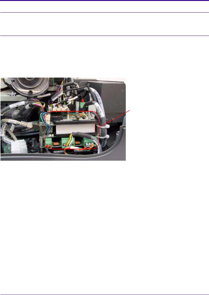
Scanner Left View
PM tube 
Linear motor
Roller drive motor
IMCS board
Scanner Right View
Laser unit
Power supply unit
6H4869 |
17 |
Service Guide
Component Description
Power Line Filter Module
The power line filter module filters the AC supply to the scanner. The power inlet socket, ON-OFF switch, and two fuses are located on the module.
IMCS Board
The IMCS board is a module stacked in four layers. It comprises the motion board and the sensor board, which is on the top layer. The IMCS board controls all four scanner motors and is responsible for all scanner sequences: loading, scanning, erasing, unloading, and ejecting the cassette.
The motion board and sensor board can be replaced either separately or as a single component. The supplied replacement unit is an entire IMCS board assembly. If you need to replace one of these boards separately you must first separate the replacement board from the replacement unit.
Motion board
|
Sensor Board Connectors |
|
|
J501 |
Reserved |
|
|
J502 |
Roller Forward Sensor |
|
|
J503 |
Reserved |
|
|
J504 |
Loop Solenoid |
|
|
J505 |
Screen Carriage Sensor (Z0) |
|
|
J506 |
Reserved |
|
|
J507 |
Reserved |
|
|
J508 |
Loader Back Position |
|
|
J510 |
Cover Sensor |
|
|
J511 |
W0 Sensor |
|
|
J512 |
15 x 30 Cassette Adapter Sensor |
|
|
J513 |
Cassette Presence Sensor |
|
|
J514 |
Cassette Hold Sensor |
|
|
J515 |
Left Limit Sensor |
|
|
J516 |
Right Limit Sensor (Home Sensor) |
|
|
J517 |
Reserved |
|
|
J519 |
Reserved |
|
|
18 |
6H4869 |
System Description
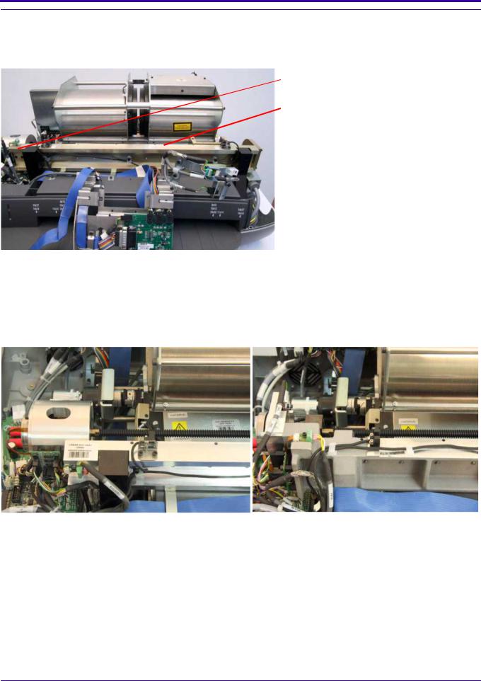
Linear Slide Assembly
Overview
The linear slide assembly moves the PM assembly and the laser within the drum to read the phosphor screen.
Linear motor
Linear screw
There are two replacement procedures for the linear slide assembly:
•Linear screw replacement. See Replacing the Linear Screw Type A on Page 48.
•Linear motor replacement. See Replacing the Linear Motor Type A on Page 54.
Two Types of Linear Screws
Type A |
|
Type B |
|||
|
|
|
|
|
|
|
|
|
|
|
|
|
|
|
|
|
|
|
|
|
|
|
|
|
|
|
|
|
|
|
|
|
|
|
|
|
|
|
|
|
|
6H4869 |
19 |
Service Guide
Linear Motor
The linear motor operates the linear slide assembly.
Two Types of Linear Motors
Type A |
|
Type B |
||
|
|
|
|
|
|
|
|
|
|
|
|
|
|
|
|
|
|
|
|
|
|
|
|
|
Optical Head Assembly
The optical head assembly controls the laser module beam. The laser module beam emits the light to energize the phosphor screen.
Optical head assembly
Optical head connector bracket
 Laser board
20 |
6H4869 |
System Description
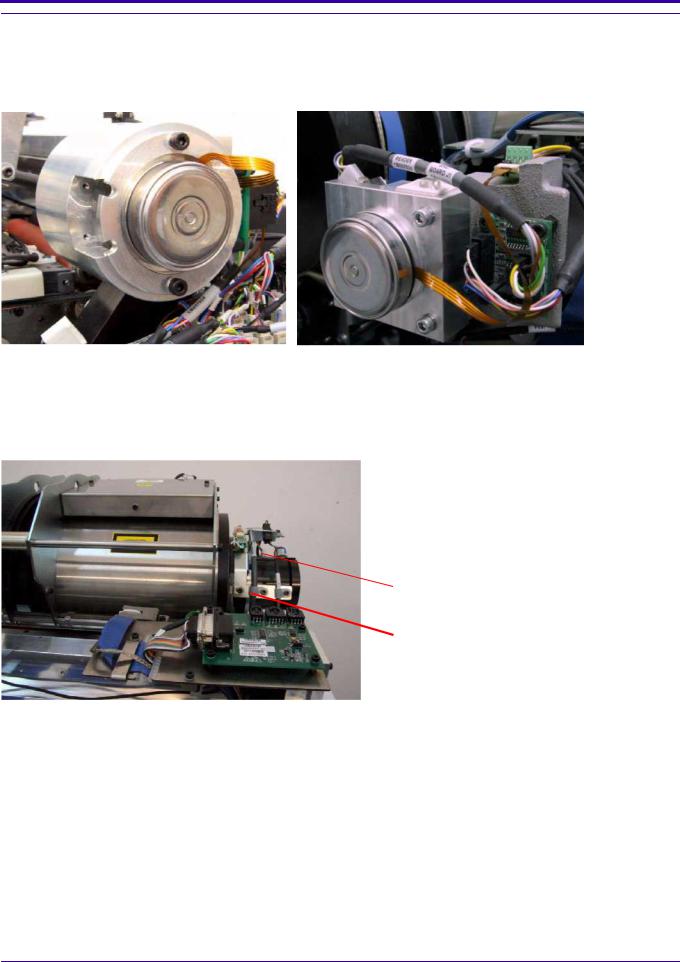
Photo Multiplier Assembly (PM)
The photo multiplier (PM) tube collects the photons emitted from the screen.
PM tube
There are two replacement procedures for the photo multiplier:
•PM board replacement. See Replacing the Photo Multiplier Board on Page 39.
•PM assembly replacement. See Replacing the Photo Multiplier Assembly on Page 41.
Photo Multiplier assembly
6H4869 |
21 |

Service Guide
Loader Stepper Assembly
The loader stepper assembly extracts the screen from the cassette and assists in inserting the screen into the cassette.
Loader pusher
Retainer screws
Roller Drive Motor Assembly
The roller drive motor assembly pulls the phosphor screen from the cassette into the drum.
22 |
6H4869 |

System Description
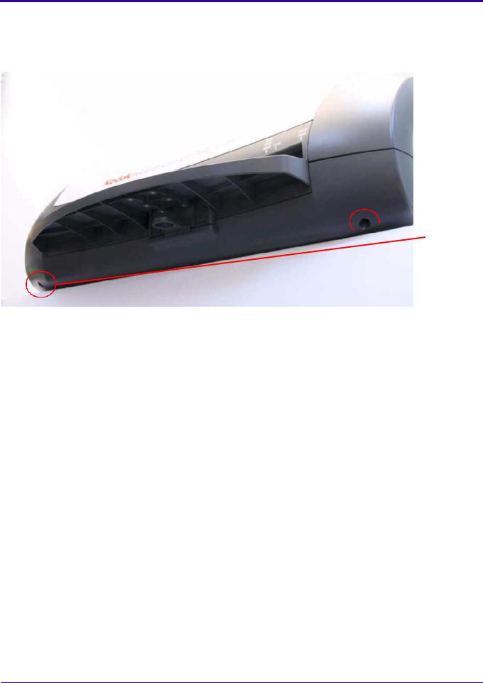
Right and Left Limit Sensors
The right and left limit sensors control the maximum left/right (X-axis) movement of the linear motor of the PM mounted on the slide.
6H4869 |
23 |

Service Guide
Section 3: Service Procedures
Service Tools
The following is a list of tools required for service operations:
•Phillips (cross-head) screwdriver (medium)
•Flat screwdriver
•Allen wrenches (metric): 0.89, 1.5, 2, 2.5, 3, 3.5, 4, 5
•Open-ended wrenches (metric): 5.5, 7
•Wire cutters
•Long-nose pliers
•Multi-meter / avo (DVM)
•Safety activation key (SK000100)
•Scanning head alignment gauge (SK000099)
•Trolley roller gauge (0.3 mm and 0.4 mm) (SK000024)
•Safety eyewear (The required laser safety eyewear must be intended for HeliumNeon/PDT lasers, have an optical density of 4-5 wavelengths of 610-695 nm, and be marked as having CE approval.)
24 |
6H4869 |
Service Procedures
Removing the Scanner Cover
[1]Switch OFF the scanner.
[2]With the system upright, pull the scanner to the edge of the table so that the front side is extended slightly over the table edge.
 Scanner cover screws
[3]Remove the 2 scanner cover screws using a 5 mm Allen wrench.
[4]Remove the 2 scanner cover screws at the back of the scanner (one on each side) using a 5 mm Allen wrench.
[5]Lift off the cover.
Installing the Scanner Cover
[1]Check (in this order):
a.The scanner is switched OFF.
b.The safety interlock key is not in the interlock.
c.The laser board DIP switch is switched ON.
[2]Install the scanner cover.
[3]Install the 4 scanner cover screws.
[4]Switch ON the scanner.
6H4869 |
25 |

Service Guide
Activating the Scanner Without the Cover
Activation Procedures
 Laser Warning
Do not operate the unit while the laser is connected without proper eye protection. Safety glasses (see Laser Safety Instructions on Page 10) must be worn by all personnel in the area of the unit! Only authorized personnel may remove the cover. Before operating the unit without the cover, disconnect the laser (see Activating the Scanner Without the Cover (Laser Deactivated) on Page 26).
When the scanner cover is removed, the safety electrical interlock switch disconnects the erasing CCFL assembly, the laser, and all motors.
To activate the scanner without the cover, use the applicable procedure:
•If the laser is not needed. See Activating the Scanner Without the Cover (Laser Deactivated) on Page 26.
•If the laser is needed. See Activating the Scanner without the Cover (Laser Activated) on Page 27.
Activating the Scanner Without the Cover (Laser Deactivated)
Before Service Operations
Laser board DIP switch
[1] Switch OFF the DIP switch on the laser board.
Activation key inserted
Activation key not inserted 
[2]Insert the safety interlock activation key into the safety interlock to the left of the roof assembly.
[3]Switch ON the scanner and perform the necessary operations.
26 |
6H4869 |

Service Procedures
After Service Operations
After performing service operations, before installing the scanner cover:
[1]Switch OFF the scanner.
[2]Remove the safety interlock activation key from the safety interlock.
[3]Switch ON the DIP switch on the laser board.
Activating the Scanner without the Cover (Laser Activated)
Before Service Operations
 Laser Warning
Refer to Laser Safety Instructions on Page 10.
Activation key inserted
Activation key not inserted 
[1]Insert the safety interlock activation key into the safety interlock.
[2]Switch ON the scanner and perform the necessary operations.
[3]If the laser is no longer needed, switch OFF the DIP switch.
After Service Operations
After performing service operations, before installing the scanner cover:
[1]Switch OFF the scanner.
[2]Remove the safety interlock activation key from the safety interlock.
[3]If the DIP switch on the laser board is OFF, switch it ON.
6H4869 |
27 |

Service Guide
Replacing the Power Line Filter Module
Tools Required
•Socket wrench
•2.0 mm Allen wrench
•2.5 mm Allen wrench
Removing the Power Line Filter Module
 Laser Warning
.Refer to Laser Safety Instructions on Page 10.
[1]Switch OFF the power and disconnect the power cable from the power inlet socket of the scanner.
[2]Remove the scanner cover. (See Removing the Scanner Cover on Page 25.)
 Structure bar
 Power line filter module
[3] Remove the lower left structure bar using a 2.5 mm Allen wrench.
[4] Remove the 2 screws above and below the ON/OFF switch using a 2 mm Allen wrench.
28 |
6H4869 |

Service Procedures
[5]Remove the 2 screws retaining the module bracket using the 2.5 mm Allen wrench.
[6]Remove the nuts retaining the ground cables to the ground stud using a socket wrench.
[7]Remove the ground cable of the power line filter from the stud.
[8]Disconnect the 2 power connectors.
[9]Remove the module together with the module bracket from the scanner.
Installing the Power Line Filter Module
 Module bracket
 Power line filter module
[1]Set the new power line filter module into the module bracket.
[2]Insert the module into the scanner.
[3]Connect the 2 power connectors to the module.
 Note
Note
Connect black wire No. 1 to P and black wire No. 2 to N.
[4]Connect the 3 ground wires to the stud and tighten the nut.
[5]Insert the bracket screws.
 Laser Warning
Refer to Laser Safety Instructions on Page 10.
[6]Connect the system to the main power and confirm that the system is operating properly.
[7]Install the scanner cover. See Installing the Scanner Cover on Page 25.
6H4869 |
29 |

Service Guide
Replacing the Fuses
Tools Required
•Flat screwdriver
•Replacement fuses (2)
Procedure
[1]Switch OFF the scanner.
[2]Disconnect the scanner from the main power.
Fuse drawer
[3] Locate the fuse drawer on the power inlet module.
[4] Open the drawer using a flat screwdriver, prying gently from the plastic tab.
30 |
6H4869 |
Loading...