


 Loading...
HP DesignJet T730 Printer & HP DesignJet
T830 MFP
Service Manual
Edition 2 |
Legal notices |
© 2015, 2016 HP Development Company, L.P. |
This document contains proprietary |
|
information that is protected by copyright. All |
|
rights are reserved. No part of this document |
|
may be photocopied, reproduced, or translated |
|
to another language without the prior written |
|
consent of HP. |
Warranty
The information contained in this document is subject to change without notice.
HP makes no warranty of any kind with regard to this material, including, but not limited to, the implied warranties of merchantability and tness for a particular purpose.
HP shall not be liable for errors contained herein or for incidental or consequential damages in connection with the furnishing, performance, or use of this material.
Safety
The procedures described in this manual are to be performed by P-quali ed service personnel only.
Electrical shock hazard
•Unplug the printer from the wall before performing any maintenance or servicing operation.
•Prevent water or any liquids form running onto electrical components or circuits.
Electrostatic discharge
See Electrostatic Discharge (ESD) Precautions on page 254 for actions you should take to prevent damage to the printer circuits from electrostatic discharge.
Safety symbols
Serious hazards leading to death, injury, or damage may result if you do not take the following precautions:
•The Warning symbol calls attention to a procedure, practice, or the like, which, if not correctly performed or adhered to, could result in personal injury. Do not proceed beyond a Warning symbol until the indicated conditions are fully understood and met.
•The Caution symbol calls attention to an operating procedure, practice, or the like, which, if not correctly performed or adhered to, could result in damage to or destruction of part or all of the printer. Do not proceed beyond a Caution symbol until the indicated conditions are fully understood and met.

Using this manual
This service manual contains information necessary to test, maintain, and service the following:
HP DesignJet T730 Printer |
F9A29A |
|
|
HP DesignJet T830 MFP |
F9A30A |
|
|
For information about using these printers, see the user's guide.
Readership
The procedures described in this service manual are to be performed by HP Certi ed service personnel only.
Part numbers
Part numbers for printer service parts are located in Parts and diagrams on page 227.
ENWW |
v |
vi |
Using this manual |
ENWW |

Table of contents
1 Printer fundamentals .................................................................................................................................... |
1 |
Overview ................................................................................................................................................................ |
1 |
Using the front panel ............................................................................................................................................. |
2 |
Start up process - preparing the ink system for the rst time ............................................................................. |
4 |
Start-up sequence ................................................................................................................................................. |
5 |
Subsystems ............................................................................................................................................................ |
7 |
2 Troubleshooting .......................................................................................................................................... |
59 |
Printer troubleshooting flowchart: SFP .............................................................................................................. |
60 |
Printer troubleshooting flowchart: MFP .............................................................................................................. |
61 |
Printer startup troubleshooting .......................................................................................................................... |
62 |
Basic printer troubleshooting .............................................................................................................................. |
64 |
System error codes .............................................................................................................................................. |
68 |
Paper troubleshooting ...................................................................................................................................... |
100 |
Communication troubleshooting ...................................................................................................................... |
111 |
Manual driver installation ................................................................................................................................. |
116 |
Drivers Troubleshooting .................................................................................................................................... |
120 |
Ink-supplies troubleshooting ............................................................................................................................ |
122 |
Print-quality troubleshooting ........................................................................................................................... |
133 |
Print mode summary table ............................................................................................................................... |
149 |
Printer Emulation .............................................................................................................................................. |
150 |
Scan and copy quality troubleshooting ............................................................................................................. |
151 |
The scanner diagnostic plot .............................................................................................................................. |
168 |
Scanner jam removal ......................................................................................................................................... |
174 |
Scan media does not load ................................................................................................................................. |
176 |
Update the rmware ......................................................................................................................................... |
176 |
3 Support Menus, Diagnostic Plots & Calibrations ........................................................................................... |
181 |
Support menus .................................................................................................................................................. |
182 |
Entering the support menus ............................................................................................................................. |
182 |
Support menu .................................................................................................................................................... |
185 |
ENWW |
vii |
Extended Support menu .................................................................................................................................... |
216 |
7. Scanner diagnostics (included only in Extended Support Menu) ................................................................. |
219 |
Diagnostic Plots & Calibrations ......................................................................................................................... |
222 |
4 Parts and diagrams .................................................................................................................................... |
227 |
Introduction ....................................................................................................................................................... |
228 |
Printer stand ...................................................................................................................................................... |
229 |
Stand HW SV kit ................................................................................................................................................. |
230 |
Covers HP DesignJet T730 Printer ..................................................................................................................... |
231 |
Covers HP DesignJet T830 MFP ......................................................................................................................... |
232 |
Roll covers ......................................................................................................................................................... |
233 |
Right-hand assemblies ...................................................................................................................................... |
234 |
Left-hand assemblies ........................................................................................................................................ |
236 |
Carriage assembly ............................................................................................................................................. |
238 |
Paper path (front) .............................................................................................................................................. |
239 |
Paper path (rear) ................................................................................................................................................ |
240 |
Spindle ............................................................................................................................................................... |
241 |
Sensor Kit ........................................................................................................................................................... |
242 |
Cable Kit ............................................................................................................................................................. |
243 |
Ink tubes (RIDS) and Ink Supply Station (ISS) .................................................................................................... |
244 |
Scanner Lid ........................................................................................................................................................ |
245 |
Scanner Bottom Mech ....................................................................................................................................... |
246 |
Scanner Bottom-EE ........................................................................................................................................... |
247 |
Scanner Back ..................................................................................................................................................... |
248 |
Miscellaneous parts ........................................................................................................................................... |
249 |
5 Removal and installation ........................................................................................................................... |
251 |
Introduction ....................................................................................................................................................... |
254 |
Customer Self Repair parts ............................................................................................................................... |
256 |
Videos available ................................................................................................................................................. |
257 |
Recommended checks after replacing parts .................................................................................................... |
257 |
Top window SFP F9A29-67007 ......................................................................................................................... |
258 |
Front Cover ........................................................................................................................................................ |
261 |
Right Cover MFP SV Kit F9A30-67011 ............................................................................................................... |
264 |
Left Cover MFP SV Kit F9A30-67012 ................................................................................................................. |
268 |
Roll Cover ........................................................................................................................................................... |
272 |
Back Cover ......................................................................................................................................................... |
275 |
Front Panel SFP F9A29-67008 .......................................................................................................................... |
278 |
Central Cover ..................................................................................................................................................... |
284 |
Upper-Roll Paper Guide ..................................................................................................................................... |
289 |
Left Roll Support ................................................................................................................................................ |
292 |
viii |
ENWW |
Right Roll Support ............................................................................................................................................. |
297 |
Encoder Strip ..................................................................................................................................................... |
300 |
Printer NVM backup PCA .................................................................................................................................... |
305 |
Power Supply ..................................................................................................................................................... |
308 |
Main PCA ............................................................................................................................................................ |
311 |
Paper Motor ....................................................................................................................................................... |
317 |
Encoder PCA and Index ...................................................................................................................................... |
319 |
Encoder Disk ...................................................................................................................................................... |
323 |
Trailing Cable ..................................................................................................................................................... |
326 |
Service Station ................................................................................................................................................... |
334 |
Prime Pump ....................................................................................................................................................... |
340 |
Carriage and Belt ............................................................................................................................................... |
344 |
Carriage Belt ...................................................................................................................................................... |
351 |
Right Gear Train Module .................................................................................................................................... |
353 |
Starwheel Assembly .......................................................................................................................................... |
356 |
Output Shaft ...................................................................................................................................................... |
358 |
Output Tray ........................................................................................................................................................ |
365 |
Multi-Sheet Tray Assembly ................................................................................................................................ |
367 |
Multi-Sheet Tray Assembly Extensions ............................................................................................................. |
368 |
Output Platen .................................................................................................................................................... |
370 |
Carriage Motor ................................................................................................................................................... |
374 |
Cutter Assembly ................................................................................................................................................ |
378 |
Multi-Sheet Tray Sensor Assembly ................................................................................................................... |
385 |
Out-Of-Paper Sensor ......................................................................................................................................... |
388 |
Out-Of-Paper Sensor Cable ............................................................................................................................... |
392 |
Output Tray Sensor Assembly ........................................................................................................................... |
395 |
Output Tray Extender Sensor Cable .................................................................................................................. |
398 |
Carriage Line Sensor .......................................................................................................................................... |
402 |
Bundle Board ..................................................................................................................................................... |
406 |
Bundle Board FFC cable ..................................................................................................................................... |
408 |
Pinchwheels ....................................................................................................................................................... |
414 |
Left Spittoon ...................................................................................................................................................... |
420 |
Scanner Top Cover F9A30-67015 ...................................................................................................................... |
423 |
Scanbars F9A30-67017 (HP DesignJet T830 MFP only) ................................................................................... |
425 |
Top Cover Button Latch F9A30-67016 (HP DesignJet T830 MFP only) ............................................................ |
430 |
Bottom Platen F9A30-67042 ............................................................................................................................ |
431 |
Scan Bundle Board F9A30-67029 ..................................................................................................................... |
433 |
Scanner Feed Motor F9A30-67024 ................................................................................................................... |
435 |
Hinges F9A30-67019 (HP DesignJet T830 MFP only) ....................................................................................... |
437 |
Scanner Feedshaft (Front) F9A30-67025 ......................................................................................................... |
440 |
Scanner Feedshaft (Rear) .................................................................................................................................. |
446 |
ENWW |
ix |
Bottom Cables F9A30-67034 ............................................................................................................................ |
448 |
OPT Wheel F9A30-60038 .................................................................................................................................. |
453 |
Sensor SV Kit F9A30-67031 .............................................................................................................................. |
454 |
Rear Cover (MFP only) ........................................................................................................................................ |
464 |
Scanbar FFC F9A30-67018 ................................................................................................................................ |
466 |
Printer Sensor Kit SV ......................................................................................................................................... |
473 |
Calibration Surface F9A30-67027 .................................................................................................................... |
484 |
Calibration Slider ............................................................................................................................................... |
487 |
Calibration Surface Gear Train F9A30-67028 ................................................................................................... |
489 |
Lower Pinch Assembly with Mirror F9A30-67033 (HP DesignJet T830 MFP only) ........................................... |
492 |
RIDS (Ink Tubes) ................................................................................................................................................. |
494 |
ISS ...................................................................................................................................................................... |
499 |
Front Window MFP SV Kit F9A30-67013 ........................................................................................................... |
502 |
Refeed Preventer ............................................................................................................................................... |
504 |
Scanner Module ................................................................................................................................................. |
505 |
Top Lid Mirror and Magnet (HP DesignJet T830 MFP only) ............................................................................... |
511 |
Input platen SV F9A30-67039 (HP DesignJet T830 MFP only) ......................................................................... |
513 |
Diverter SV F9A30-67040 ................................................................................................................................. |
516 |
Diverter bottom part F9A30-67062 .................................................................................................................. |
520 |
Latch (Right) F9A30-67030 ............................................................................................................................... |
522 |
Latch (Left) F9A30-67030 ................................................................................................................................. |
524 |
Front Panel and Left Trim F9A30-67043 .......................................................................................................... |
526 |
6 Preventive maintenance ............................................................................................................................. |
529 |
Preventive maintenance .................................................................................................................................... |
530 |
Preventive maintenance kits ............................................................................................................................. |
537 |
7 Safety precautions .................................................................................................................................... |
541 |
General safety guidelines .................................................................................................................................. |
542 |
Electrical / Fire hazard ....................................................................................................................................... |
542 |
Mechanical hazard ............................................................................................................................................. |
542 |
Warning labels ................................................................................................................................................... |
542 |
8 Appendices ................................................................................................................................................ |
543 |
Important links .................................................................................................................................................. |
544 |
Support Menu and Extended Support Menu Tree ............................................................................................. |
545 |
How to check whether your computer is connected to your network .............................................................. |
546 |
Wireless troubleshooting report error cases .................................................................................................... |
549 |
Media Advance Calibration report (Tap 11) ....................................................................................................... |
557 |
Rugged Case Accessory ..................................................................................................................................... |
561 |
x |
ENWW |
CSR fliers ............................................................................................................................................................ |
567 |
FAQ: Tips & Tricks .............................................................................................................................................. |
596 |
ENWW |
xi |
xii |
ENWW |

1Printer fundamentals
●Overview
●Using the front panel
● |
Start up process - preparing the ink system for the rst time |
●Start-up sequence
●Subsystems
Overview
Feature |
HP DesignJet T730 |
|
HP DesignJet T830 |
More information |
|
|
|
|
|
Paper source |
Roll, Manual sheet, and Multi-sheet tray |
See the user's guide |
||
|
|
|
|
|
Hardware di erences |
Single function printer |
|
Multifunction printer with |
|
|
|
|
integrated scanner |
|
|
|
|
|
|
Connectivity |
Wi-Fi or Fast Ethernet Lan and USB Host (Printing from USB/Scan |
Important! Cannot have both |
||
|
|
to USB) |
WiFi and LAN at the same time |
|
|
|
|
|
|
Web Services |
Automatic |
rmware upgrade |
The printer needs to be |
|
|
|
|
|
Internet-connected: For some |
|
Printing by email |
con gurations, the latest |
||
|
rmware release is needed. |
|||
|
|
|
|
Manual rmware update is |
|
Customer Involvement Program (Printer use data sent regularly |
available in both printers via HP |
||
|
Designjet Utility (Windows) or |
|||
|
under customer acceptance) |
|||
|
HP Utility (Mac OS) and also via |
|||
|
|
|
|
|
|
|
|
|
USB host. The same rmware |
|
|
|
|
le is used for T730 and T830. |
|
|
|
||
Mobility |
Mobile "In-Os" Print support: (IOS, Android), HP AiO App |
See user guide |
||
|
|
|
|
|
Print speed |
28 s per page on A1/D in |
|
28 s per page on A1/D in |
|
|
Economode |
|
Economode |
|
|
|
|
|
|
Default print mode |
|
Fast |
|
|
|
|
|
||
Print resolution |
Up to 1200 × 2400 dpi |
|
||
|
|
|
||
Memory and languages |
1 GB, HP-GL/2 (processing in printer) |
|
||
|
|
|
|
|
ENWW |
Overview 1 |
Feature |
HP DesignJet T730 |
HP DesignJet T830 |
More information |
|
|
|
|
Supplies |
Ink supplies HP 728 40 ml and 130 ml Cyan, Magenta, Yellow |
Ink cartridges and printhead |
|
|
|
|
can be replaced by the |
|
HP 728 69 ml and 300 ml Black |
customer. |
|
|
|
|
|
|
HP 729. One on Axis PRINTHEAD for all colors |
|
|
|
|
|
|
Using the front panel
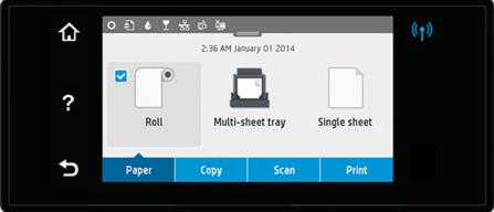
The front panel is a touch-sensitive screen with a graphical user interface; it is located on the front left of the printer. It gives you complete control of your printer: from the front panel, you can print, view information about the printer, change printer settings, perform calibrations and tests, and so on. The front panel also displays alerts (warning and error messages) when needed.
The front panel has a large central area to display dynamic information and icons. At the top of the central area there is a dashboard that displays the Home screen icons. To interact with these icons swipe across the dashboard to access the Home screen.
On the left and right sides you can see up to six xed icons at di erent times. Normally they are not all displayed at the same time.
Left and right xed icons
● shows the status of the wireless connection: if the blue light is shining, the wireless connection is active.
●Press  to return to the home screen.
●Press  to view help about the current screen.
●Press  to go back to the previous screen without discarding changes.
2 Chapter 1 Printer fundamentals |
ENWW |

Paper tab icons
The following items are displayed only on the paper tab screen:
●Press  to load, unload, and change options for roll paper.
●Press  to change options for the multi-sheet tray, or activate it.
●Press  to load, unload, and change options for single sheets.
 NOTE: The white tick in a blue box indicates the active paper source: in this example, the multi-sheet tray:
 .
.
 NOTE: It is not possible to use wireless and wired network connections simultaneously.
 NOTE: If no tick appears, no paper is loaded in any source.
Dashboard icons
The following items are displayed only on the paper tab screen:
●Press  to change printer settings.
●Press  to eject paper from the scanner.
●Press  to view information about ink supplies.
●Press  to view information about the printhead.
●Press  to view information about network status, and con gure the network (wireless or wired).
●Press  to access access Web Services.
●Press  to access WiFi Direct.
If the printer is left idle for some time, it goes into sleep mode and switches o the front-panel display. To change the time that elapses before sleep mode, slide  , then Printer setup > Sleep mode. You can set a time between 5 and 240 minutes.
The printer wakes from sleep mode and switches on the front-panel display whenever there is some external interaction with it.
You can use the printer’s auto-o feature to turn the printer o automatically. For example, setting it to 2 hours turns the printer o after 2 hours of inactivity. In this way, you can save more energy. However, the auto-o feature is automatically disabled when the printer is connected to the network, to avoid inconveniencing network users.
The following table shows an overview of the two types of support menu available, for more details see Entering the support menus on page 182.
 NOTE: The icons mentioned in this table will not be visible in the front panel: you must press the front panel in the places where they normally appear, as shown in the front panel illustration at the start of this section.
ENWW |
Using the front panel 3 |
Label |
Description |
|
|
|
|
|
|
||||
Support menu: This can be used by customers under the |
From the Home screen, press the following icons one after the |
||||
guidance of phone call agents assisting remotely. Using this |
other: |
, |
, |
, . |
|
menu, customers can perform troubleshooting tasks and access |
|
|
|
|
|
printer information. |
If there is a system error, you may not be able to reach the home |
||||
|
screen. In this case, press the Power button and hold it down for |
||||
|
15 seconds. |
|
|
|
|
|
|
||||
Extended Support menu: Service engineers only |
From the Home screen, press the following icons one after the |
||||
|
other: |
, |
, |
, |
. |
|
|
|
|
|
|
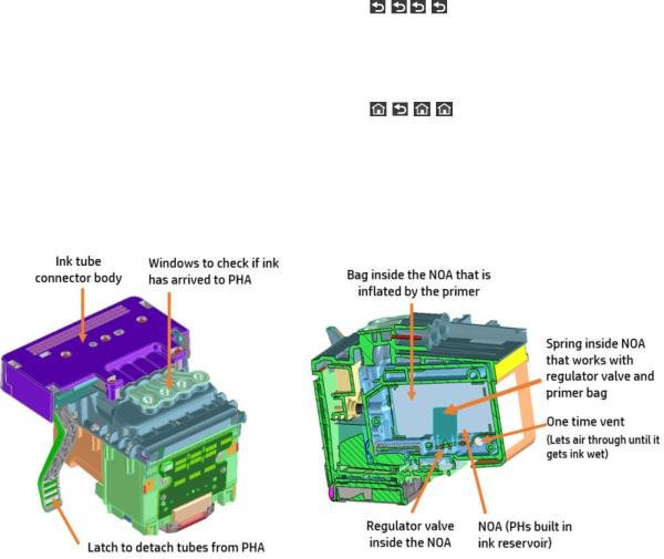
Start up process - preparing the ink system for the rst time
The printer tubes and PHA are shipped dry. To ready them to print, they must be lled with ink, and need servicing to make the nozzles wet, and manage air within the PHA.
Three subsystems are primarily involved in this process: the ink supply station, the primer, and the service station.
●The ink supply station pumps ink from the supplies, through the tubes, to the PHA.
●The primer opens the PHA regulator to allow ink to enter the PHA. It also manages the air within the PHA, moving any air bubbles to the upper part of the PHA reservoirs (also known as NOAs).
● |
The service station cleans the PHA nozzles after the process, readying the PHA for the rst print. |
The process flow is as follows:
1.The primer activates to inflate the bag inside the printhead so that the regulator is open during start-up.
|
The primer air circuit holds the regulator open during the start-up ink ll process. |
2. |
Once the regulator is open, the ink supply station starts pumping to push ink through the tubes. The rst |
|
ink is used to ll up the empty tubes. The air in the tubes is purged out of the one-time vent in the PHA. |
3. |
Once the tubes are lled, ink lls the NOA to the one-time vent. Air continues to purge out of the vent. |
|
When the ink reaches the one-time vent, it becomes wet and the air in the PHA remains. Extra ink is sent |
4 Chapter 1 Printer fundamentals |
ENWW |

for fully wetting the vent, and purge the air from the pores at which point the vent is closed and remains closed for the life of the PHA.
4.The air circuit is vented and the PHA bag is deflated. Now ink pumps in to return to the volume to what the bag had before moving from full inflation to set point. This closes the regulator.
5.With the PHA full of ink, a series of lower pressure primes are run to expel all air from the PHA below the lter into the NOA.
6.Finally the servicing routine begins, and the PHA nozzles are cleaned and prepared to print.
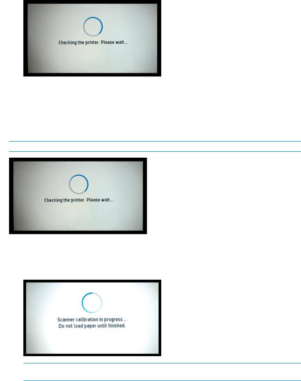
Start-up sequence
There are 4 states between power-on and the Home screen:
1.Electronics initialization
2.Firmware initialization
3.Mechanical initialization
4.Scanner calibration
State 1: Electronics initialization
1.The front panel moves from flashing white light to turning dark.
2. The printer reads the rmware from the eMMC module.
 NOTE: At this stage, if something is broken, it will not be possible to enter the Support menu. To diagnose what is happening, go to the front panel blank troubleshooting.The Front Panel is blank (the printer does not start) on page 64. Subsequently, you can enter the Support menu to troubleshoot if necessary.
State 2: Firmware initialization
1.HP logo appears on a white background.
2.Bundle board and ASICs are initialized. The Firmware is loaded.
ENWW |
Start-up sequence 5 |
3.When complete, the screen changes to:
State 3: Mechanical initialization
1.A basic check of servos is run.
2.Next, it checks that the Scan Axis and Paper Axis are unobstructed by scraps of paper or other items.
3.Finally the media and ink system are initialized.
 NOTE: During all steps, the screen "Checking the printer. Please wait..." is shown:
State 4: Scanner calibration (MFP only)
▲MFP only: Every time the unit starts up PRNU calibration (white balancing) is conducted to ensure best calibration and to improve IQ. During calibration, the following screen is shown:
 NOTE: Initialization lasts around 2 minutes with clean power-o (Front Panel Power button). If there was a dirty power-o , the printer requires more time to inititialize to ensure the printhead is OK.
6 Chapter 1 Printer fundamentals |
ENWW |
Subsystems
Printer
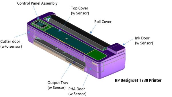
Covers
Functionality
These parts cover the printing mechanism and act as protection from potential knocks or dust. They also prevent the customer from coming into contact with unsafe parts during the operation of the printer. Finally, the covers complement the style and aesthetics of the printer.
ENWW |
Subsystems 7 |
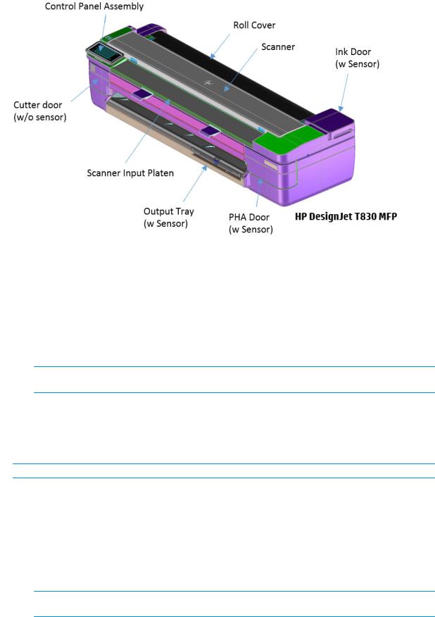
Components
Other than the cosmetic aspects of the covers, there are several sensors related to the subsystem covers. The sensors are designed to detect the status of the cover, open or closed.
●The Ink Door Sensor senses whether the Ink Cartridge Cover is open or closed. Opening the Ink Cartridge Cover starts ink cartridge replacement automatically. The sensor is hosted in the printer chassis.
●HP Designjet T730 Printer only: The Central Cover hosts the Top Cover Sensor to sense whether the Central Window is open or closed.
 IMPORTANT: HP Designjet T730 Printer only: Be careful to avoid damaging the sensor while removing the Central Cover. See Central Cover on page 284.
●The PHA Door sensor detects the door opening so that the printer is aware of the user’s intention of interacting with the PHI connector or PHA.
●The Output Tray Sensor senses whether the Output Tray is open or closed. To avoid paper jams while printing on roll paper, the tray should be closed.
 IMPORTANT: Damage to the covers can cause the sensors to malfunction.
Removal and installation
In order to proceed with the removal and installation of the covers its important to bear in mind their cosmetic aspects. It is recommended that you use gloves for any service operation involving the covers.
Due to the layout of the covers, it is important to bear in mind that some parts require removal before you can remove a speci c cover.
●Right Cover requires Front Cover removal.
 IMPORTANT: Right cover removal interacts with the ink tubes. There is only one way to remove the right cover; with the ink door open and the PHA door closed.
8 Chapter 1 Printer fundamentals |
ENWW |
Ink door cover interaction with chassis:
◦Right cover interaction with ink tubes:
● With the PHA door closed, the tubes move freely:
ENWW |
Subsystems 9 |
●With the PHA door open, the tubes are held by a lever:
●Left Cover requires Front and Cutter Door Removal.
●Roll Cover requires Right and Left Cover removal.
●HP DesignJet T730 Printer only: Central Cover requires Right Cover and Left Cover removal.
Electronics
Other than the sensor boards, there are no electronics related to this subsystem.
Printhead health systems: Service Station, Primer system, and Left Spittoon
Functionality
The service station is responsible for printhead maintenance. It takes action to clean ink residues and service ink nozzles, and prevents ink from drying in critical zones by capping the printhead once printing has nished.
The Primer system provides the necessary air pressure to the printhead to perform initialization. This system also provides pressure to the necessary printhead service operations (by boosting air which pushes ink out through the printhead nozzles, cleaning residues of dried ink and other particles).
The Left spittoon is a small container located to the left of the print-zone area, this is the area used by the printhead to “spit” a small amount of ink at the end/beginning of the printing swath in order to ensure correct nozzle heath for left-to-right printing.
10 Chapter 1 Printer fundamentals |
ENWW |
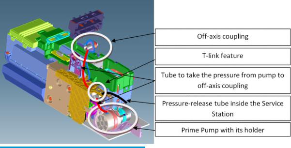
Components
Item |
Function |
|
|
O -axis coupling assembly |
This is a rubber spring link located on the side plate of the scan |
|
axis (area where the Carriage moves). It links the primer system |
|
with the Carriage when the Carriage is located in its maximum left |
|
position. This system ensures the pressure from the primer |
|
reaches the printhead for nozzle servicing. |
|
|
Prime Pump |
This is an air pump which provides the necessary pressure for |
|
printhead servicing and nozzle repair. The Prime Pump is |
|
suspended on a rubber holder to minimize the noise that the |
|
Prime Pump makes while in operation. |
|
|
Primer Tubes |
The tubes take the air from the Prime Pump to the o -axis |
|
coupling. There is a T link feature connected to a tube that goes |
|
inside the service station; the purpose of this tube is to release |
|
the air pressure from the system. The tube is pinched by the |
|
shuttle of the service station when reaching a certain position; |
|
this action closes the circuit and allows the system to be |
|
pressurized. With the movement of the service station the tube is |
|
released, allowing the pressure from the system to escape. |
|
|
Notes and considerations
Any leakage in the primer system will generate poor or no priming, this will a ect nozzle heath (or even cause the printhead startup to fail). Bear in mind that the system is not just for the Prime Pump and tubes, the prime pressure is transmitted via the o -axis coupling to the Carriage and from there to the printhead assembly and from there to the cartridges.
ENWW |
Subsystems 11 |

 NOTE: There is no pressure sensor in the system. The Prime Pump operates at a certain time to reach a speci c pressure level, the system is depressurized by releasing the pinching of the release tube in the Service Station (by moving the service station).


 NOTE: It is important to ensure the Carriage reaches the maximum left position; if not, the o -axis coupling will not connect the Prime Pump with the Carriage. Also, the coupling is made of a rubbery material, degradation of the material will a ect Primer performance due to air leaks.
Electronics
The control driver of the Prime Pump is located on the printer bundle board located on the right-hand side of the printer. There is no encoder for the Prime Pump. This pump is managed only by a DC motor activated for a certain period of time to create the required priming pressure.
Printhead assembly
Notes and considerations
The printhead operates as a full assembly, regulating ink flow in the NOA regulator, and warehousing air during the life of the PHA. This is done by balancing pressure between the inside of the NOA regulator and atmosphere. When ink is printed out, the pressure becomes more negative inside the chamber, causing the bag to open, which allows more ink into the system, putting it back into equilibrium and closing the regulator.
There are 4 colors on the die. With the PCA facing away from you, the color order is Black, Cyan, Magenta, and Yellow.
12 Chapter 1 Printer fundamentals |
ENWW |

When the PHA is empty when replaced. The system uses the startup routine to ll the PHA and prepare it for the rst page of printing. When performing a PHA replacement it is necessary to have enough ink in the cartridges, as prompted by the front panel. As noted in the section on the RIDS (Ink Tubes) on page 494; when the tubes are empty, a new, empty printhead must be used.
 NOTE: HOT SWAP is not allowed: If the PHA is replaced with the printer turned ON, there is a risk of Main PCA damage if the printhead replacement front panel procedure is not followed.
Electronics
The PHA is controlled through the carriage PCA and trailing cables to power the printhead and transmit data. It is connected on the backside of the carriage.
ENWW |
Subsystems 13 |
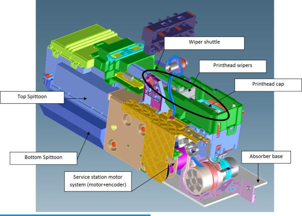
Service Station system
Functionality
Item |
Function |
|
|
Printhead Wipers |
These are rubber paddles that are passed through the nozzle |
|
plate of the printhead with the Service Station movement. They |
|
clean the excess ink from the nozzle plate with a rubbing action. |
|
|
Printhead Cap |
This caps and protects the nozzles from drying when they are not |
|
printing. |
|
|
Service Station Motor system |
This moves the shuttle with the wiper and the cap so that these |
|
two items can perform their functions. The system is composed |
|
of a DC motor and an encoder disk with an encoder sensor to read |
|
the motor position. |
|
|
Bottom Spittoon |
This part acts as an ink reservoir when spitting and nozzle health |
|
operations are performed. It contains diapers that absorb ink and |
|
keeps it contained. |
|
|
14 Chapter 1 Printer fundamentals |
ENWW |

Item |
Function |
|
|
Top Spittoon |
This seals the reservoir and completes the main body of the |
|
service station. |
|
|
Wiper Shuttle |
This mobile part is propelled by the motor that contains the Wiper |
|
and Cap. Depending on the position, spitting, wiping, capping, or |
|
priming can take place: |
|
Spitting: The printhead “spits” a little ink into the spittoon to get |
|
the nozzles conditioned and ready for the next swath of printing. |
|
Wiping: A physical action to pass the rubber wipers through the |
|
printhead nozzles. |
|
Capping: Parking the printhead to maintain nozzle heath during |
|
printer inactivity, with a surrounding seal. |
|
Priming: Squirts ink through the nozzles to clean and unblock |
|
them. |
|
|
Notes and considerations
The service station is o ered as a complete service part for full replacement. The failures from this subsystem are usually related to the mobile parts: motor or encoder failures that prevent the shuttle from reaching the positions for capping or uncapping.
With the life primer system, tube pinching can present an issue (although it is designed to function for the life of the printer).
When the Service Station is replaced, it is mandatory to reset the Preventive Maintenance Kit for the Service Station, this will trigger a simple calibration that is done with the Service Station on the next printer startup. The calibration measures the length of the Service Station (shuttle front bump to shuttle rear bump), which ensures a correct capping position.
Electronics
All the controlled movements for the Service Station are done from the Printer Bundle Board located on the right-hand side of the printer. Issues with the Service Station can also be related to this control board.
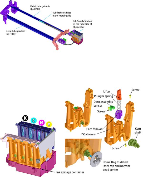
Ink system overview
The ink system consists on the Ink Supply Station to pump ink from the supplies and the Ink Tubes to carry ink to the printhead.
ENWW |
Subsystems 15 |
Below the two main systems mentioned are described.
Ink Supply Station (ISS)
The Ink Supply Station (ISS) pumps ink from the supplies to tubes in order to print. The ISS acumen sensors identify HP ink supplies.
The ISS is mounted on the right of the printer so as to pump ink from the supplies to the PHA. Several of their main components are carry-over parts from other products.
The ISS is designed to admit di erent supply types: Mirasis (130 cc), Mirasis Plus (300 cc) and Oasis (69 cc), with four di erent colors; Cyan (C), Magenta (M), Yellow (Y), Black (PK).
The Printer Bundle Board that controls the Primer, Ink Door Sensor, PHA Cover Sensor, Pick motor, ISS motor, ISS acumen sensor, ISS home flag encoder and Service Station motor is located just next to the ISS. The cables must be routed correctly (by means of wire saddles xed in the Printer Bundle Board support), to prevent interference and wire pinching whenever the Right Cover is assembled.
16 Chapter 1 Printer fundamentals |
ENWW |

Ink Tubes (RIDS)
The tubes connect the Ink Supply Station with the printhead and ensure ink is transferred from the supplies to the printhead. The tubes are independent of the Trailing Cables.
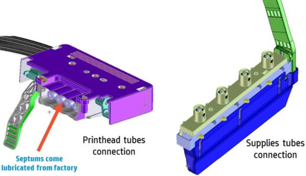
The PHA connector is not connected to the carriage, but a floating connector and the septums come prelubricated. Good lubrication is essential for easy insertion in the printhead.
ENWW |
Subsystems 17 |
The supplies end is embedded in the Ink Supply Station and its design is very similar to other products. There is a risk that when removing the tubes from the printer some ink spillage can occur.
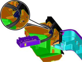
Printhead-Ink Tubes connection
This latch allows for the removal and installation of the o -axis ink tubes that go to the printhead assembly.
The ink tubes come connected to the printhead and are pre-installed in the carriage, but manual connection must be performed by the customer when a printhead replacement is required.
18 Chapter 1 Printer fundamentals |
ENWW |
Loading...