


 Loading...
HP Designjet 820, Designjet 4500, Designjet 4520, Designjet T1100, Designjet T1120 service manual
...DESIGNJET scanners: 820 MFP, 4500 Scanner/MFP, 4520 Scanner/MFP, HD Scanner, T1100 MFP, T1120 HD MFP and T1200 HD MFP series
Service manual
© Copyright Hewlett-Packard Company 2012
For HP Internal Use Only
7th edition
Legal notices
This document contains proprietary information that is protected by copyright. All rights are reserved. No part of this document may be photocopied, reproduced, or translated to another language without the prior written consent of Hewlett-Packard Company.

Notices
Warranty
The information contained in this document is subject to change without notice.
Hewlett-Packard makes no warranty of any kind with regard to this material, including, but not limited to, the implied warranties of merchantability and fitness for a particular purpose.
Hewlett-Packard shall not be liable for errors contained herein or for incidental or consequential damages in connection with the furnishing, performance, or use of this material.
WARNING! The procedures described in this manual are to be performed by HP-qualified service personnel only.
Electrical Shock Hazard
Serious shock hazard leading to death or injury may result if you do not take the following precautions:
●Ensure that the AC power outlet (mains) has a protective earth (ground) terminal.
●Disconnect the product from the power source prior to performing any maintenance.
●Prevent water or any other liquids from running onto electrical components or circuits, or through openings in the enclosure.
Electrostatic Discharge
See Electrostatic Discharge (ESD) Precautions on page 65 for precautions you should take to prevent damage to the printer circuits from electrostatic discharge.
Safety Symbols
General definitions of safety symbols are given immediately after the table of contents.
WARNING! The Warning symbol calls attention to a procedure, practice, or the like, which, if not correctly performed or adhered to, could result in personal injury. Do not proceed beyond a Warning symbol until the indicated conditions are fully understood and met.
CAUTION: The Caution symbol calls attention to an operating procedure, practice, or the like, which, if not correctly performed or adhered to, could result in damage to or destruction of part or all of the product. Do not proceed beyond a Caution symbol until the indicated conditions are fully understood and met.
Content Management Department, Large Format Printing
Barcelona Division,
Hewlett-Packard Espanola, S.A.
Camí de Can Graells, 1–21
08174 Sant Cugat del Vallès
Spain
ENWW |
iii |
iv Notices |
ENWW |
Using this Manual
Purpose
This Service Manual contains information necessary to troubleshoot and service:
●HP Designjet 820 MFP, Model Q6685
●HP Designjet 4500 Scanner, Model Q1277A
●HP Designjet 4500 MFP, Model Q1276A
●HP Designjet 4520 Scanner, Model CM770A
●HP Designjet 4520 HD MFP, Model CM769A
●HP Designjet HD Scanner, Model CQ654A & CQ654B.
●HP Designjet T1100 MFP, Model Q6713A
●HP Designjet T1120 HD MFP, Model CK841A
●HP Designjet T1200 HD MFP, Model CQ653A & CQ653B.
For information about using the product, see the corresponding user guide.
This Service Manual is about the Scanner and the integration with the printer as a copier. In order to troubleshoot the printer, see the corresponding Service Manual for the printer.
Readership
The procedures described in this Service Manual are to be performed by HP Certified service personnel only.
Part Numbers
Part Numbers for service parts can be found in Parts and Diagrams on page 49.
ENWW |
v |
vi Using this Manual |
ENWW |

Table of contents
1 Troubleshooting |
|
Troubleshooting tips ............................................................................................................................. |
1 |
Is the problem with the Printer or the Scanner? ................................................................................... |
1 |
Image-quality problems ........................................................................................................................ |
2 |
Output problems ................................................................................................................................... |
2 |
Troubleshooting System Error Codes .................................................................................................. |
2 |
Using the SCANtest 6 Diagnostic Software ......................................................................................... |
2 |
Troubleshooting Issues ........................................................................................................................ |
6 |
Troubleshooting print-quality and copy issues ..................................................................................... |
7 |
Troubleshooting general scanner issues ............................................................................................ |
10 |
Troubleshooting Specific Scanner Issues .......................................................................................... |
18 |
Cleaning the Scanning Area ............................................................................................................... |
20 |
Troubleshooting Specific Panel PC Problems .................................................................................... |
23 |
Preventive Maintenance Kit for HP Designjet Scanners .................................................................... |
29 |
2 System Error Codes |
|
System Error Codes for the Scanner Only ......................................................................................... |
31 |
Error Codes for the JetImage Software RIP ....................................................................................... |
39 |
Error Messages for the Touch Screen ............................................................................................... |
45 |
3 Parts and Diagrams |
|
Copier Stand & Touch Screen ............................................................................................................ |
50 |
Copier Covers .................................................................................................................................... |
52 |
Top Assemblies .................................................................................................................................. |
53 |
Inside Guide Plate .............................................................................................................................. |
54 |
Drive Assemblies ................................................................................................................................ |
55 |
Camera Components and Fan ........................................................................................................... |
56 |
Electronic Boards ............................................................................................................................... |
57 |
Panel PC ............................................................................................................................................ |
57 |
Panel PC Cabinet Components (Part 1) ............................................................................................ |
58 |
Panel PC Cabinet Components (Part 2) ............................................................................................ |
60 |
Miscellaneous items ........................................................................................................................... |
61 |
4 Removal and Installation |
|
Introduction ......................................................................................................................................... |
64 |
Safety Precautions ............................................................................................................................. |
64 |
Electrostatic Discharge (ESD) Precautions ........................................................................................ |
65 |
ENWW |
vii |
Required Tools ................................................................................................................................... |
65 |
Top Cover ........................................................................................................................................... |
66 |
Left Cover ........................................................................................................................................... |
67 |
Right Cover ........................................................................................................................................ |
68 |
Rear Cover ......................................................................................................................................... |
72 |
Top Profile .......................................................................................................................................... |
73 |
Guide Plate ......................................................................................................................................... |
76 |
Guide Plate ......................................................................................................................................... |
80 |
Glass Plate ......................................................................................................................................... |
81 |
Entry Roller Shield .............................................................................................................................. |
82 |
Exit Roller Shield ................................................................................................................................ |
83 |
Camera Motor .................................................................................................................................... |
84 |
Camera Lens Assembly ..................................................................................................................... |
85 |
Camera Board .................................................................................................................................... |
86 |
Power Supply Board ........................................................................................................................... |
88 |
Driver Board ....................................................................................................................................... |
90 |
Fan ..................................................................................................................................................... |
92 |
Main Electronics Board ...................................................................................................................... |
93 |
Interface Board ................................................................................................................................... |
95 |
Stepper Motor ..................................................................................................................................... |
96 |
Fluorescent Lamp ............................................................................................................................... |
98 |
Elevation Motor Driver Board ............................................................................................................. |
99 |
Elevation Motor ................................................................................................................................ |
102 |
Entry Roller ....................................................................................................................................... |
105 |
Exit Roller ......................................................................................................................................... |
110 |
Exit Roller ......................................................................................................................................... |
118 |
Entry Media Sensor .......................................................................................................................... |
119 |
Exit Media Sensor ............................................................................................................................ |
120 |
Belt ................................................................................................................................................... |
121 |
Bottom Cover ................................................................................................................................... |
123 |
Mirror Chassis .................................................................................................................................. |
126 |
Stitching Wire ................................................................................................................................... |
128 |
White Background Assembly ........................................................................................................... |
130 |
PanelPC ........................................................................................................................................... |
131 |
Open Cabinet ................................................................................................................................... |
131 |
Screen Bezel .................................................................................................................................... |
134 |
LCD .................................................................................................................................................. |
134 |
Back Plate (rev A scanners) ............................................................................................................. |
136 |
CPU Cooling Fan ............................................................................................................................. |
137 |
CPU .................................................................................................................................................. |
138 |
DRAM PCA ...................................................................................................................................... |
139 |
DVD Drive ........................................................................................................................................ |
140 |
Hard Disk Drive (rev A) .................................................................................................................... |
142 |
Hard Disk Drive (HD and T1200 rev B) ............................................................................................ |
144 |
LCD Controller PCA (rev A) ............................................................................................................. |
145 |
Inverter PCA ..................................................................................................................................... |
146 |
HDD/DVD Deck (rev A) .................................................................................................................... |
147 |
viii |
ENWW |
HDD/DVD Deck (rev B) .................................................................................................................... |
148 |
Main PCA (rev A) ............................................................................................................................. |
149 |
Main PCA (rev B) ............................................................................................................................. |
152 |
Power Supply Unit (rev A) ................................................................................................................ |
153 |
Power Supply Unit (rev B) ................................................................................................................ |
155 |
System Fan ...................................................................................................................................... |
156 |
5 Scanner Adjustments and Calibrations |
|
Introduction ....................................................................................................................................... |
158 |
Tools Required ................................................................................................................................. |
158 |
Terminology ...................................................................................................................................... |
159 |
Camera Design Overview ................................................................................................................ |
159 |
Adjusting the Camera manually ....................................................................................................... |
162 |
Adjusting the Camera Using the Camera Wizard ............................................................................. |
172 |
Scanner Maintenance ...................................................................................................................... |
179 |
ATAC Position Sensors check ......................................................................................................... |
179 |
Original Guide Sensor Test .............................................................................................................. |
180 |
Calibrate ATAC (Automatic Thickness Adjustment Control) ............................................................ |
184 |
Driver Board Communication Test ................................................................................................... |
185 |
Upgrade Scanner Firmware ............................................................................................................. |
186 |
ENWW |
ix |
x |
ENWW |
1 Troubleshooting
●Troubleshooting tips
●Is the problem with the Printer or the Scanner?
●Image-quality problems
●Output problems
●Troubleshooting System Error Codes
●Using the SCANtest 6 Diagnostic Software
●Troubleshooting Issues
●Troubleshooting print-quality and copy issues
●Troubleshooting general scanner issues
●Troubleshooting Specific Scanner Issues
●Cleaning the Scanning Area
●Troubleshooting Specific Panel PC Problems
●Preventive Maintenance Kit for HP Designjet Scanners
Troubleshooting tips
1.First record whether the problem is with the Printer, the Scanner, or the Touch Screen.
2.Make sure that the scanning area is completely clean.
3.Test 20: Noise Test can help you find where the scanning area is dirty.
4.The SCAN dump files can help you to understand the light profile of the affected scanner.
5.Remember, in order to cancel when copying, press the Cancel button on the Touch Screen and the Cancel button on the printer.
Is the problem with the Printer or the Scanner?
If you experience the following symptoms, the problem could be related to the scanner:
●System Error on the Touch Screen.
●LED’s flashing on the Scanner Operator Panel.
●WIDEsystem error message.
●Vertical lines (either color or black) in the scanned image.
ENWW |
Troubleshooting tips 1 |
If you experience the following symptoms, then perform an Image Preview and send a Test Print:
●Image Quality Problems.
●No Output
●Output is not as expected.
If the Image preview fails, this points to a problem with the Scanner. If the Test Print fails, this points to a problem with the Printer.
Image-quality problems
If you have Image Quality problems in any prints, try the following:
1.Print out a file already stored or print out a demo file.
2.Once the print is finished, insert it into the Scanner.
3.Once scanned, print out the scanned image.
●If the original print is the same as the copied print, then the problem is associated with the Printer.
●If the original print is NOT the same as the copied print, then the problem is associated with the Scanner.
Output problems
If the output is not as you expected it to be, try the following:
●Check all the settings in the Software: Color Settings and Margins.
●Check media settings: Media profile (in software) and media loaded in the printer (front panel selection) should be the same.
●Perform Color Calibration (both Scanner and printer).
●Check the Preview Image.
If there is no output at all, then try the following:
●Check the connection between the Printer and the scanner.
●Check the selected settings: List, Collate, Scan to file...
Troubleshooting System Error Codes
Chapter 2, System Error Codes on page 30, contains a list of system error codes and their respective descriptions and recommended corrective actions. Only try one recommended action at a time and check if the error code has disappeared.
Using the SCANtest 6 Diagnostic Software
Here we briefly describe the various tests found in the SCANtest 6 Diagnostic Software, for more detail of some of the Adjustments shown below see Chapter 5, Scanner Adjustments and Calibrations
on page 158.
The purpose of the SCANtest 6 diagnostic software is to support the troubleshooting and adjustment of the Scanner.
2 Chapter 1 Troubleshooting |
ENWW |
To access the software you must go to the Setup tab and to: Options, System, Service (this part is password protected, the password is ’support' Scantest.
When the SCANtest 6 diagnostic software has been started, the Scanner is switched ON in Test Mode, and the Diagnostic LED on the Operator Panel is turned ON.
Scanner Test Program Menu
●Test 1: Scanner Information
●Test 2: LED Test
●Test 3: Key Test
●Test 4: Original-Sensor Test
●Test 5: Lamp Test
●Test 6: Motor Test
●Test 7: Complete Hardware Test
●Test 9: Camera Adjustment
●Test 11: Stitching and Vertical Alignment
●Test 12: Adjust Y-Axis Scaling
●Test 13: Switch Scanner to Test Mode
●Test 20: Noise Test
●Test 21: Scan Dump
●Test 27: Camera Adjustment Wizard
●Test 28: Original Guide Sensor Test
●Test 30: Calibrate ATAC
●Test 31: Driver Board Communication Test
If SCANtest 6 is started when the scanner is in Error Mode, the Error Code Number and a short description of the error will be displayed on the screen.
Test 1: Scanner Information
This test displays general information regarding the scanner. When executed, the test displays the following:
●Scanner Model:
●Firmware Release:
●Firmware Release Date:
●Firmware Build:
●FPGA Revision:
●FPGA Release Date:
●Boot Code Revision:
●Boot Code Release Date:
ENWW |
Using the SCANtest 6 Diagnostic Software 3 |
●Scanner ID Switch:
●SCSI ID:
Test 2: LED Test
This test checks the functionality of the LED Indicators on the Operator Panel. When the test is executed, all the LEDs are sequentially switched ON/OFF until Test 2 is terminated. If any of the LEDs fail, you will NOT get an error message, instead the LED will NOT switch ON or OFF. If the LED test fails, replace the Right Cover (which contains the Operator Panel).
Test 3: Key Test
This test checks the functionality of the Keys on the Operator Panel. When the test is executed, each key on the Operator Panel will turn the LED ON when pressed.
Key |
LED |
|
|
Forward and Reverse |
Ready (Green) |
|
|
Power |
Wait (Yellow) |
|
|
ATAC control key |
|
|
|
The only way to know if the test fails is by inspection, there is no error message that is displayed.
If the Key test fails, replace the Right Cover (which contains the Operator Panel).
Test 4: Original-Sensor Test
This test checks the functionality of the Media Sensors.
When the test is executed, the following LEDs turn ON when one of the Media Sensors is activated.
Actuator |
LED |
|
|
Media Entry Sensor |
Ready (Green) |
|
|
Media Exit Sensor |
Ready (Green) |
|
|
To test the Media Sensors, load a Sheet of media (A4) and the Ready LED switches ON and when you remove it the Ready LED switches OFF.
If the test fails (if any of the LEDs fail to switch ON), then the problem will be related to corresponding Sensor.
Test 5: Lamp Test
This test checks the functionality of the Lamp and associated electronics.
When the test is executed, a message on the screen will indicate whether the Lamp is turned ON or OFF (Lamp power is turned ON/OFF) and whether the Light is ON/OFF (Light is detected or not). The Lamp is delayed for approximately 2 seconds when switched ON.
Test 6: Motor Test
This test checks the functionality of the Stepper Motor and any associated electronics.
When the test is executed, a menu appears that allows you to select the motor speed and the motor direction.
4 Chapter 1 Troubleshooting |
ENWW |

If the Stepper Motor or the Driver Board fails to run when the test is executed, then the Stepper Motor should be replaced.
Test 7: Complete Hardware Test
This test checks the various functions of the Driver and Camera Boards.
Test 9: Camera Adjustment
 NOTE: This is the recommended way to adjust the cameras. However, Test 27 (the Camera Adjustment Wizard) is provided as an easier alternative.
This test contains a Software Oscilloscope that allows you to check and adjust the CCD-Cameras. The following functions can be selected from the Test Program Menu.
●Uncorrected or Corrected Light Profile.
●Red, Green, or Blue Color Channel.
●Special Detail Views for Light Profile, Scan Width, and Vertical Positioning.
●Forward / Reverse controls for the Camera Motor.
●Save screen images.
●Print screen images.
The content of the Detail Views is marked on the upper overview window by red vertical lines. The continuous lines refer to the left Detail View and the dashed lines to the right Detail View.
Test 11: Stitching and Vertical Alignment
This test is also included in the Scanner Maintenance Software.
This test performs Automatic Vertical Alignment and Horizontal Stitching.
Once the test has been started:
●Insert Calibration Sheet.
●Select Vertical Alignment to align the cameras.
●Select Horizontal Stitching to stitch the cameras. The screen image can be saved or printed.
This test allows manual setting of the Stitch Values. The Stitch Values are stored in the Flash Memory on the Driver Board.
The Vertical Alignment may be adjusted manually by controlling the Camera Motor from the control field '<< dddd>>'. The two buttons marked ''<<' respectively '>>' are used to start the motor and to determine the direction of rotation. When started, the motor runs for dddd mili-seconds as entered into the control field.
Test 12: Adjustment of Y-Axis Scaling
This test allows you to adjust the Y-Axis Scaling.
The scaling (dpi) in the mechanical scan direction (Y-Axis) depends on the speed of the stepper motor relative to the scanline Exposure Time. The default motor speed can be changed ± 1%, either from Test 12 or by using the ‘Scanner Setup/Correction factor …’ option of SW copying. The correction factor is stored in the Flash Memory on the Driver Board.
Test 13: Switch Scanner to Test Mode
ENWW |
Using the SCANtest 6 Diagnostic Software 5 |
This test allows you to switch the scanner back to Test Mode. Useful if the scanner gets out of Test Mode, e.g. if it has to be turned OFF/ON during troubleshooting.
Test 20: Noise Test
The purpose of this test is to detect and locate the possible cause (dust, dirt, scratches,..) of vertical lines running from top to bottom of the scanned image.
When the test is executed, it scans the White Calibration Area of the Calibration Sheet and displays, for each color channel, the graytone values of each separate pixel averaged over the scanned band.
The displayed image of the Calibration Sheet will be superimposed by low level noise caused by the CCD chip, and larger spikes most likely caused by dust, dirt, scratches, or similar defects on the Glass Plate. In rare cases, larger spikes may be caused by dust, dirt, or pixel faults on the CCD chip.
The positions of larger spikes are shown by the numbers (cm or inch units) opposite to the spikes. The numbers refer to the Sideload-ruler on the scanner. Larger spikes going downwards are often caused by dust, dirt, scratches, or similar defects on the Glass Plate and may be removed by cleaning the Glass Plate. Downward spikes often show up as darker vertical lines in the scanned image.
Larger spikes going upwards are often caused by dust or dirt present on the Glass Plate during the last calibration with Scanner Maintenance. These defects are memorized by the Light Profiles stored in the Flash Memory and can only be removed by cleaning of the Glass Plate followed by running Scanner Maintenance again. Upward spikes show up as very bright vertical lines in the scanned image.
White vertical lines in the scanned image may be found even if Noise Test shows a perfectly ‘clean’ scanner. In this case, the cause may be white dust or particles on the backside of the Glass Plate having the same color as the white background. In this case, the Light Profiles of SCANtest 6, Test 9 may show upwards going spikes when a dark original is placed in the scan area.
Test 21: SCANdump
SCANdump is a tool for remote diagnostic. SCANdump saves the light profile from the cameras, error codes, and statistics.
When the test is executed, the file SCANdump.con will be placed in the directory c:\Temp\.
Test 27: Camera Adjustment Wizard
This allows you to adjust the camera using a wizard that guides you through the complete process. Use this test (instead of Test 9) only if you have no experience in adjusting the camera. See Adjusting the Camera Using the Camera Wizard.
Test 28: Original Guide Sensor Test
This is to test the Guide Plate Sensors which are located under the Guide Plate. See Original Guide Sensor Test.
Test 30: Calibrate ATAC (Automatic Thickness Adjustment Control)
This test sets the current level at which the ATAC will stop if something is preventing it from moving down. See Calibrate ATAC (Automatic Thickness Adjustment Control).
Test 31: Driver Board Communication Test
This test checks the communication between the Scanner and the Driver Board. See Driver Board Communication Test.
Troubleshooting Issues
The following guide will help you to find a solution to some typical problems that some customers may experience. The problems (P#) that can be solved remotely through on-phone support and customer
6 Chapter 1 Troubleshooting |
ENWW |

intervention are marked C. The problems that require on-site intervention performed by a Support Technician are marked T.
 NOTE: Before sending a Support Technician to the customer, identify whether the problem is related to the scanner or the Panel PC (PPC).
If the problem is scanner-related, erase the parameter block and run the scanner maintenance. Then perform the system recover using the most recent version of the software.
If the problem is PPC-related, perform the system recovery using the most recent version of the software.
If the problem persists, try the solutions listed in the tables below.
Troubleshooting print-quality and copy issues
P# |
Category |
Problem |
Q# |
Question |
Yes/ |
C/T |
Solution |
|
|
|
|
|
No |
|
|
|
|
|
|
|
|
|
|
1 |
Copy |
The colors on one |
1 |
Have you cleaned |
No |
C |
Camera differences - The scanner |
|
problem |
side of the copy |
|
and calibrated |
|
|
needs to be cleaned and calibrated |
|
|
do not |
|
your scanner |
|
|
(see P24 on page 17 and P25 |
|
|
correspond to the |
|
recently? |
|
|
on page 17) |
|
|
colors on the |
|
|
|
|
|
|
|
|
|
Yes |
|
See Q2 |
|
|
|
other side of the |
|
|
|
||
|
|
copy |
|
|
|
|
|
|
|
|
|
|
|
|
|
|
|
|
2 |
Have you |
No |
C |
Upgrade system software (use Update |
|
|
|
|
upgraded the |
|
|
System DVD) |
|
|
|
|
system software |
|
|
|
|
|
|
|
Yes |
T |
Cameras need adjusting or the |
|
|
|
|
|
to the latest |
|||
|
|
|
|
version? |
|
|
Camera Board replacing |
|
|
|
|
|
|
|
|
P# |
Category |
Problem |
Q# |
Question |
Yes/ |
C/T |
Solution |
|
|
|
|
|
No |
|
|
|
|
|
|
|
|
|
|
2 |
Copy |
I get thin lines of |
1 |
Are the lines |
Yes |
C |
Erase the parameter block and run the |
|
problem |
wrong colors in |
|
vertical and also |
|
|
scanner maintenance. Then clean and |
|
|
my copy |
|
present in your |
|
|
calibrate the scanner (see P24 |
|
|
|
|
preview? |
|
|
on page 17 and P25 on page 17) |
|
|
|
|
|
|
|
|
|
|
|
|
|
No |
|
See Q2 |
|
|
|
|
|
|
|
|
|
|
|
2 |
Are the lines |
Yes |
C |
Check printheads by starting |
|
|
|
|
horizontal and |
|
|
printhead test on Printer. By using the |
|
|
|
|
equally spaced? |
|
|
built-in test print function in the |
|
|
|
|
|
|
|
Designjet Scan Copy application, you |
|
|
|
|
|
|
|
can also get an idea whether the |
|
|
|
|
|
|
|
Printer is performing OK |
|
|
|
|
|
|
|
|
|
|
|
|
|
No |
|
See Q3 |
|
|
|
|
|
|
|
|
|
|
|
3 |
Are the lines |
Yes |
C |
The lines could be caused by a data |
|
|
|
|
horizontal, but |
|
|
error. Upgrade system software |
|
|
|
|
irregular (maybe |
|
|
|
|
|
|
|
No |
|
See Q4 |
|
|
|
|
|
only 1 line)? |
|
||
|
|
|
|
|
|
|
|
|
|
|
4 |
Do you have a |
Yes |
T |
You have a camera error. Replace |
|
|
|
|
great number of |
|
|
Camera Board |
|
|
|
|
regular spaced |
|
|
|
|
|
|
|
lines very close to |
|
|
|
|
|
|
|
each other and |
|
|
|
|
|
|
|
restricted to one |
|
|
|
|
|
|
|
side (1 camera) |
|
|
|
|
|
|
|
only? |
|
|
|
|
|
|
|
|
|
|
|
ENWW |
Troubleshooting print-quality and copy issues |
7 |
P# |
Category |
Problem |
Q# |
Question |
Yes/ |
C/T |
Solution |
|
|
|
|
|
No |
|
|
|
|
|
|
|
|
|
|
3 |
Copy |
I get thick lines of |
1 |
Are the lines |
Yes |
C |
The scanner needs to be cleaned and |
|
problem |
slightly wrong |
|
vertical and also |
|
|
calibrated (see P24 on page 17 and |
|
|
colors in my copy |
|
present in your |
|
|
P25 on page 17) |
|
|
|
|
preview? |
|
|
|
|
|
|
|
No |
|
See Q2 |
|
|
|
|
|
|
|
||
|
|
|
|
|
|
|
|
|
|
|
2 |
Are the lines |
Yes |
C |
Check printheads by starting |
|
|
|
|
horizontal and |
|
|
printhead test on Printer. By using the |
|
|
|
|
equally spaced? |
|
|
built-in test print function in the |
|
|
|
|
|
|
|
Designjet Scan Copy application, you |
|
|
|
|
|
|
|
can also get an idea whether the |
|
|
|
|
|
|
|
Printer is performing OK |
|
|
|
|
|
|
|
|
|
|
|
|
|
No |
|
See P2 on page 7 |
|
|
|
|
|
|
|
|
P# |
Category |
Problem |
Q# |
Question |
Yes/ |
C/T |
Solution |
|
|
|
|
|
No |
|
|
|
|
|
|
|
|
|
|
4 |
Copy |
Some colors are |
1 |
Is the scanner |
No |
C |
See P1 on page 7. Clean and calibrate |
|
problem |
not the same |
|
clean and |
|
|
the scanner (see P24 on page 17 |
|
|
when I compare |
|
calibrated? |
|
|
and P25 on page 17) |
|
|
the master print |
|
|
|
|
|
|
|
|
|
Yes |
|
See Q2 |
|
|
|
with the copy |
|
|
|
||
|
|
|
|
|
|
|
|
|
|
|
2 |
Do you use the |
No |
C |
If you are using e.g. Glossy Media for |
|
|
|
|
correct media |
|
|
this copy, the media profile selected |
|
|
|
|
profile for the |
|
|
should also be for Glossy Media. |
|
|
|
|
actual media? |
|
|
|
|
|
|
|
Yes |
|
See Q3 |
|
|
|
|
|
|
|
||
|
|
|
|
|
|
|
|
|
|
|
3 |
Is the media |
No |
C |
Create a new media profile (see P26 |
|
|
|
|
profile valid? |
|
|
on page 17) |
|
|
|
|
|
|
|
|
|
|
|
|
|
Yes |
|
See Q4 |
|
|
|
|
|
|
|
|
|
|
|
4 |
Is the option 'Ink |
No |
C |
If original was printed using an Inkjet |
|
|
|
|
Printer Original' |
|
|
Printer, set this option (see P27 |
|
|
|
|
set in accordance |
|
|
on page 17) |
|
|
|
|
with your |
|
|
|
|
|
|
|
Yes |
|
See Q5 |
|
|
|
|
|
original? |
|
||
|
|
|
|
|
|
|
|
|
|
|
5 |
Is the media you |
No |
C |
e.g. Use Glossy Media to reproduce a |
|
|
|
|
are printing on the |
|
|
Glossy original |
|
|
|
|
same type as the |
|
|
|
|
|
|
|
Yes |
C |
Create a new media profile (see P26 |
|
|
|
|
|
original? |
|||
|
|
|
|
|
|
|
on page 17) |
|
|
|
|
|
|
|
|
P# |
Category |
Problem |
Q# |
Question |
Yes/ |
C/T |
Solution |
|
|
|
|
|
No |
|
|
|
|
|
|
|
|
|
|
5 |
Copy |
Only a part of the |
1 |
Are you scanning |
Yes |
C |
Uncheck extended media handling |
|
problem |
master print is |
|
a thick original? |
|
|
box in scanner settings (using |
|
|
being copied |
|
|
|
|
extended media will load the original |
|
|
|
|
|
|
|
between both entry and exit rollers |
|
|
|
|
|
|
|
before scanning - this means that you |
|
|
|
|
|
|
|
will not have the start of the thick |
|
|
|
|
|
|
|
original scanned. Also the scan speed |
|
|
|
|
|
|
|
will be slower, and no "back - ups"/ |
|
|
|
|
|
|
|
reversing is allowed while scanning) |
|
|
|
|
|
|
|
|
|
|
|
|
|
No |
|
See Q2 |
|
|
|
|
|
|
|
|
8 Chapter 1 Troubleshooting |
ENWW |
P# |
Category |
Problem |
Q# |
Question |
Yes/ |
C/T |
Solution |
|
|
|
|
|
No |
|
|
|
|
|
|
|
|
|
|
|
|
|
2 |
Have you |
Yes |
C |
The scanner needs to be cleaned (see |
|
|
|
|
selected 'Auto |
|
|
P24 on page 17) |
|
|
|
|
size'? |
|
|
|
|
|
|
|
No |
|
See Q3 |
|
|
|
|
|
|
|
||
|
|
|
|
|
|
|
|
|
|
|
3 |
Is the length too |
Yes |
C |
The problem may be with the Printer |
|
|
|
|
short and the |
|
|
(not able to print close to the edges) or |
|
|
|
|
width OK? |
|
|
Panel PC (Hard Disk is full). |
|
|
|
|
|
|
|
|
|
|
|
|
|
No |
C |
Check that the margins that are set are |
|
|
|
|
|
|
|
not too big. Also check Scanner Media |
|
|
|
|
|
|
|
Offsets |
|
|
|
|
|
|
|
|
P# |
Category |
Problem |
Q# |
Question |
Yes/ |
C/T |
Solution |
|
|
|
|
|
No |
|
|
|
|
|
|
|
|
|
|
6 |
Copy |
Which setting will |
- |
- |
- |
C |
See section about media profile (P4). |
|
problem |
give me the best |
|
|
|
|
Use copy quality best. Choose the |
|
|
result when |
|
|
|
|
correct Type of original ("Map" for |
|
|
copying? |
|
|
|
|
maps, "Photo" for photos, etc). |
|
|
|
|
|
|
|
Eventually go to Original Setup to fine |
|
|
|
|
|
|
|
adjust colors and sharpening. (See |
|
|
|
|
|
|
|
also online help for more details - |
|
|
|
|
|
|
|
button with "?" symbol) |
|
|
|
|
|
|
|
|
P# |
Category |
Problem |
Q# |
Question |
Yes/ |
C/T |
Solution |
|
|
|
|
|
No |
|
|
|
|
|
|
|
|
|
|
7 |
Copy |
Nesting feature is |
1 |
Is the correct |
No |
C |
Select the correct Printer |
|
Problem |
not working |
|
printer selected? |
|
|
|
|
|
Yes |
|
See Q2 |
|||
|
|
|
|
|
|
||
|
|
|
|
|
|
|
|
|
|
|
2 |
Is the Hard Disk |
Yes |
C |
Free up some space, or try to run a |
|
|
|
|
close to being |
|
|
nesting job with only 2 or 3 small |
|
|
|
|
full? |
|
|
pictures. If that works, see P27 |
|
|
|
|
|
|
|
on page 17 |
|
|
|
|
|
|
|
|
|
|
|
|
|
No |
C |
Make sure that Nesting is set: |
|
|
|
|
|
|
|
Select: Output Layout Nesting |
|
|
|
|
|
|
|
optimized |
|
|
|
|
|
|
|
|
|
|
|
|
|
|
|
|
P# |
Category |
Problem |
Q# |
Question |
Yes/ |
C/T |
Solution |
|
|
|
|
|
No |
|
|
|
|
|
|
|
|
|
|
8 |
Copy |
The Collate Copy |
1 |
Is your Hard Disk |
Yes |
C |
Free up some space, or try to run a |
|
problem |
function does not |
|
close to full? |
|
|
collate job with a smaller picture. |
|
|
work |
|
|
|
|
|
|
|
|
|
No |
C |
Follow the step by step instructions in |
|
|
|
|
|
|
|||
|
|
|
|
|
|
|
the online help under Collate Copy. |
|
|
|
|
|
|
|
|
ENWW |
Troubleshooting print-quality and copy issues |
9 |
P# |
Category |
Problem |
Q# |
Question |
Yes/ |
C/T |
Solution |
|
|
|
|
|
No |
|
|
|
|
|
|
|
|
|
|
9 |
Copy |
The lines are not |
1 |
Are the lines |
Yes |
C/T |
C: The original could be curled or |
|
problem |
accurate |
|
wavy and |
|
|
crumpled. Try to flattten the original (in |
|
|
|
|
irregular? |
|
|
case of very irregular waves there |
|
|
|
|
|
|
|
could be a mechanical problem with |
|
|
|
|
|
|
|
the scanner). |
|
|
|
|
|
|
|
T: check motor and belt drive tension |
|
|
|
|
|
|
|
according to TSM |
|
|
|
|
|
|
|
|
|
|
|
|
|
No |
|
See Q2 |
|
|
|
|
|
|
|
|
|
|
|
2 |
Are the lines not |
Yes |
C/T |
C: Are you using the correct copy |
|
|
|
|
sharp? |
|
|
method? Try sharpening. If sharpness |
|
|
|
|
|
|
|
is different between Cameras, you |
|
|
|
|
|
|
|
may have a Focus Problem. |
|
|
|
|
|
|
|
T: Check focus of cameras with Focus |
|
|
|
|
|
|
|
Adjustment Pattern. |
|
|
|
|
|
|
|
|
|
|
|
|
|
No |
|
See Q3 |
|
|
|
|
|
|
|
|
|
|
|
3 |
Are the lines |
Yes |
C |
You might have a visible stitching error |
|
|
|
|
broken and the |
|
|
(see P28 on page 17) |
|
|
|
|
errors situated in |
|
|
|
|
|
|
|
No |
C |
Check the dpi. In the case of too low |
|
|
|
|
|
a vertical column |
|||
|
|
|
|
between 2 |
|
|
resolution, jagged diagonal lines will |
|
|
|
|
columns? |
|
|
appear. |
|
|
|
|
|
|
|
|
|
|
|
|
|
|
|
|
P# |
Category |
Problem |
Q# |
Question |
Yes/ |
C/T |
Solution |
|
|
|
|
|
No |
|
|
|
|
|
|
|
|
|
|
10 |
Copy |
One side of the |
1 |
Have you |
No |
C |
Upgrade scanner firmware to latest |
|
Problem |
preview is black |
|
upgraded the |
|
|
version. SeeUpgrade Scanner |
|
|
|
|
scanner firmware |
|
|
Firmware on page 186. |
|
|
|
|
to the latest |
|
|
|
|
|
|
|
Yes |
|
See Q2 |
|
|
|
|
|
version? |
|
||
|
|
|
|
|
|
|
|
|
|
|
2 |
Have you |
No |
C |
Upgrade system software (use |
|
|
|
|
upgraded the |
|
|
System Recovery DVD). |
|
|
|
|
system software |
|
|
|
|
|
|
|
Yes |
T |
Most likely a Camera Error. Perform |
|
|
|
|
|
to the latest |
|||
|
|
|
|
version? |
|
|
the Manual Camera Adjustment (Test |
|
|
|
|
|
|
|
9). Replace the Camera Board if |
|
|
|
|
|
|
|
necessary. |
|
|
|
|
|
|
|
|
Troubleshooting general scanner issues
P# |
Category |
Problem |
Q# |
Question |
Yes/ |
C/T |
Solution |
|
|
|
|
|
No |
|
|
|
|
|
|
|
|
|
|
11 |
Copy |
Only a part of the |
1 |
Are you scanning |
Yes |
C |
Uncheck extended media handling |
|
problem |
master print is |
|
a thick original? |
|
|
box in scanner settings (using |
|
|
being copied |
|
|
|
|
extended media will load the original |
|
|
|
|
|
|
|
between both entry and exit rollers |
|
|
|
|
|
|
|
before scanning - this means that you |
|
|
|
|
|
|
|
will not have the start of the thick |
|
|
|
|
|
|
|
original scanned. Also the scan speed |
|
|
|
|
|
|
|
will be slower, and no "back - ups"/ |
|
|
|
|
|
|
|
reversing is allowed while scanning). |
|
|
|
|
|
|
|
|
|
|
|
|
|
No |
|
See Q2 |
|
|
|
|
|
|
|
|
10 Chapter 1 Troubleshooting |
ENWW |
P# |
Category |
Problem |
Q# |
Question |
Yes/ |
C/T |
Solution |
|
|
|
|
|
No |
|
|
|
|
|
|
|
|
|
|
|
|
|
2 |
Have you |
Yes |
C |
The scanner needs to be cleaned (see |
|
|
|
|
selected 'Auto |
|
|
P24 on page 17) |
|
|
|
|
size'? |
|
|
|
|
|
|
|
No |
|
See Q3 |
|
|
|
|
|
|
|
||
|
|
|
|
|
|
|
|
|
|
|
3 |
Is the length too |
Yes |
C |
The problem may be with the Printer |
|
|
|
|
short and the |
|
|
(not able to print close to the edges) or |
|
|
|
|
width OK? |
|
|
Panel PC (Hard Disk is full). |
|
|
|
|
|
|
|
|
|
|
|
|
|
No |
C |
Check that the margins that are set are |
|
|
|
|
|
|
|
not too big. Also check Scanner Media |
|
|
|
|
|
|
|
Offsets. |
|
|
|
|
|
|
|
|
P# |
Category |
Problem |
Q# |
Question |
Yes/ |
C/T |
Solution |
|
|
|
|
|
No |
|
|
|
|
|
|
|
|
|
|
12 |
System Error |
What should I do |
1 |
Are you running a |
Yes |
C |
Making a copy takes a lot of resources |
|
|
when the |
|
copy job? |
|
|
according to the settings. Wait till the |
|
|
program hangs? |
|
|
|
|
copy is done before performing |
|
|
|
|
|
|
|
another action. |
|
|
|
|
|
|
|
|
|
|
|
|
|
No |
|
Restart the system. If the problem is |
|
|
|
|
|
|
|
coming back, run the System recovery |
|
|
|
|
|
|
|
(see P17 on page 13) |
|
|
|
|
|
|
|
|
P# |
Category |
Problem |
Q# |
Question |
Yes/ |
C/T |
Solution |
|
|
|
|
|
No |
|
|
|
|
|
|
|
|
|
|
13 |
File problem |
When I scan to |
1 |
Are you scanning |
Yes |
C |
Scanning large drawings will generate |
|
|
file, the file is very |
|
in color? |
|
|
very big files. An A0 color drawing |
|
|
big |
|
|
|
|
scanned at 300 dpi will generate a file |
|
|
|
|
|
|
|
size of approx. three Gigabytes when |
|
|
|
|
|
|
|
scanned in an uncompressed format. |
|
|
|
|
|
|
|
In order to reduce file size, select TIFF |
|
|
|
|
|
|
|
- pack bits as format. You can reduce |
|
|
|
|
|
|
|
size even more by selecting JPEG |
|
|
|
|
|
|
|
format, but this format will reduce |
|
|
|
|
|
|
|
picture quality. |
|
|
|
|
|
|
|
|
|
|
|
|
|
No |
|
See Q2 |
|
|
|
|
|
|
|
|
|
|
|
2 |
Are you scanning |
Yes |
C |
Scanning large drawings will generate |
|
|
|
|
in gray tones? |
|
|
big files. An A0 gray tone drawing |
|
|
|
|
|
|
|
scanned at 300 dpi will generate a file |
|
|
|
|
|
|
|
size of approx. 300 Mbytes when |
|
|
|
|
|
|
|
scanned in an uncompressed format. |
|
|
|
|
|
|
|
In order to reduce file size, select TIFF |
|
|
|
|
|
|
|
- pack bits as format. You can reduce |
|
|
|
|
|
|
|
size even more by selecting JPEG |
|
|
|
|
|
|
|
format, but this format will reduce |
|
|
|
|
|
|
|
picture quality. |
|
|
|
|
|
|
|
|
|
|
|
|
|
No |
|
In order to reduce file size on scanned |
|
|
|
|
|
|
|
B/W drawings, select TIFF group 4 |
|
|
|
|
|
|
|
compression. |
|
|
|
|
|
|
|
|
ENWW |
Troubleshooting general scanner issues 11 |
P# |
Category |
Problem |
Q# |
Question |
Yes/ |
C/T |
Solution |
|
|
|
|
|
No |
|
|
|
|
|
|
|
|
|
|
14 |
File problem |
When I scan to |
1 |
Did you get an |
Yes |
C |
Check that you have enough disk |
|
|
file my application |
|
error message |
|
|
space and scan to file again, choosing |
|
|
it cannot read the |
|
when creating the |
|
|
TIFF uncompressed as format |
|
|
file |
|
file? |
|
|
|
|
|
|
No |
C |
We only recommend to use the built-in |
||
|
|
|
|
|
|||
|
|
|
|
|
|
|
viewer for file viewing. Large format |
|
|
|
|
|
|
|
drawing files may not load correctly in |
|
|
|
|
|
|
|
other viewers due to file size. Try to |
|
|
|
|
|
|
|
scan a smaller original (A4). |
|
|
|
|
|
|
|
|
P# |
Category |
Problem |
Q# |
Question |
Yes/ |
C/T |
Solution |
|
|
|
|
|
No |
|
|
|
|
|
|
|
|
|
|
15 |
Network |
I cannot access |
1 |
Is the PC |
Yes |
C |
Do basic network troubleshooting. |
|
Problem |
the system from |
|
connected to the |
|
|
|
|
|
No |
C |
Connect the PC to the Network. |
|||
|
|
the network |
|
network? |
|||
|
|
|
|
|
|
|
|
P# |
Category |
Problem |
Q# |
Question |
Yes/ |
C/T |
Solution |
|
|
|
|
|
No |
|
|
|
|
|
|
|
|
|
|
16 |
Scan to |
I cannot access |
1 |
With the Panel |
Yes |
C |
Go to Q2 |
|
network |
network drivers |
|
PC connected to |
|
|
|
|
|
No |
C |
Check the network performance and |
|||
|
(feature only |
|
|
the LAN, can you |
|||
|
available in |
|
|
access the Panel |
|
|
connection to the scanner Panel PC. |
|
T1100 MFP) |
|
|
PC from another |
|
|
|
|
|
|
|
computer on the |
|
|
|
|
|
|
|
network? |
|
|
|
|
|
|
|
|
|
|
|
|
|
|
2 |
Is the folder of the |
Yes |
C |
Windows does not allow the same |
|
|
|
|
server you are |
|
|
server to be mapped by two different |
|
|
|
|
trying to map |
|
|
users on one computer. Use the |
|
|
|
|
already mapped |
|
|
access connection previously mapped |
|
|
|
|
by another user in |
|
|
or delete the connection and map a |
|
|
|
|
the Panel PC? |
|
|
new access connection. |
|
|
|
|
|
|
|
|
|
|
|
|
|
No |
C |
Go to Q3 |
|
|
|
|
|
|
|
|
|
|
|
3 |
Do you have |
Yes |
C |
Go to Q4 |
|
|
|
|
permission to |
|
|
|
|
|
|
|
No |
C |
You cannot access this network folder. |
|
|
|
|
|
access and write |
|||
|
|
|
|
to the network |
|
|
Select a network folder for which you |
|
|
|
|
folder you are |
|
|
have read and write permissions. |
|
|
|
|
trying to map? |
|
|
|
|
|
|
|
|
|
|
|
|
|
|
4 |
Are you using the |
Yes |
C |
Try to map the network file from |
|
|
|
|
correct user |
|
|
another computer by selecting |
|
|
|
|
name and |
|
|
Windows Explorer, Tools, Map |
|
|
|
|
password? |
|
|
network drive. If you are able to map |
|
|
|
|
|
|
|
the drive in this manner, you should |
|
|
|
|
|
|
|
also be able to map through the Panel |
|
|
|
|
|
|
|
PC. |
|
|
|
|
|
|
|
|
|
|
|
|
|
No |
C |
Use the correct user name and |
|
|
|
|
|
|
|
password. |
|
|
|
|
|
|
|
|
12 Chapter 1 Troubleshooting |
ENWW |
P# |
Category |
Problem |
Q# |
Question |
Yes/ |
C/T |
Solution |
|
|
|
|
|
No |
|
|
|
|
|
|
|
|
|
|
17 |
Recovery |
How and when is |
- |
- |
- |
C |
The recovery DVD is used if the |
|
|
the Recovery |
|
|
|
|
system needs to be reinstalled. Insert |
|
|
DVD used? |
|
|
|
|
the DVD in to the PC and reboot the |
|
|
|
|
|
|
|
system. |
|
|
|
|
|
|
|
|
P# |
Category |
Problem |
Q# |
Question |
Yes/ |
C/T |
Solution |
|
|
|
|
|
No |
|
|
|
|
|
|
|
|
|
|
18 |
Scanner |
Scanner |
1 |
Did any error |
Yes |
C |
See Q2 |
|
Calibration |
Maintenance did |
|
occur when |
|
|
|
|
|
No |
C |
Clean the scanner and then run |
|||
|
Problem |
not succeed |
|
performing the |
|||
|
|
|
|
Scanner |
|
|
Scanner Maintenance again (see |
|
|
|
|
Maintenance? |
|
|
P24 on page 17 and P25 |
|
|
|
|
|
|
|
on page 17). If that does not help, |
|
|
|
|
|
|
|
see Q5. |
|
|
|
|
|
|
|
|
|
|
|
2 |
Error: Basic |
Yes |
C |
Clean the scanner and then run |
|
|
|
|
calibration was |
|
|
Scanner Maintenance again (see |
|
|
|
|
performed. but |
|
|
P24 on page 17 and P25 |
|
|
|
|
failed to stitch |
|
|
on page 17). If that does not help, |
|
|
|
|
scanner or |
|
|
see Q5. |
|
|
|
|
Could not find |
|
|
|
|
|
|
|
No |
|
See Q3. |
|
|
|
|
|
horizontal line |
|
||
|
|
|
|
or Could not |
|
|
|
|
|
|
|
read bar lines |
|
|
|
|
|
|
|
or Could not |
|
|
|
|
|
|
|
recognize the |
|
|
|
|
|
|
|
scanned IT8 |
|
|
|
|
|
|
|
picture. |
|
|
|
|
|
|
|
|
|
|
|
|
|
|
3 |
Error: Sheet not |
Yes |
C |
Reinsert calibration sheet correctly |
|
|
|
|
recognized. |
|
|
and run Scanner Maintenance again. |
|
|
|
|
|
|
|
If that does not help, see Q5. |
|
|
|
|
|
|
|
|
|
|
|
|
|
No |
|
See Q4. |
|
|
|
|
|
|
|
|
|
|
|
4 |
Error: No |
Yes |
T |
Check the camera. |
|
|
|
|
movement in |
|
|
|
|
|
|
|
No |
|
See Q5. |
|
|
|
|
|
camera position |
|
||
|
|
|
|
has been |
|
|
|
|
|
|
|
detected during |
|
|
|
|
|
|
|
vertical camera |
|
|
|
|
|
|
|
alignment. |
|
|
|
|
|
|
|
|
|
|
|
|
|
|
5 |
Have you |
No |
C |
Upgrade system software (use Update |
|
|
|
|
upgraded the |
|
|
System DVD). Clean the scanner and |
|
|
|
|
system software |
|
|
then run Scanner Maintenance again |
|
|
|
|
to the latest |
|
|
(see P24 on page 17 and P25 |
|
|
|
|
version? |
|
|
on page 17). |
|
|
|
|
|
|
|
|
|
|
|
|
|
Yes |
T |
Check the camera. |
|
|
|
|
|
|
|
|
|
|
|
|
|
|
|
|
P# |
Category |
Problem |
Q# |
Question |
Yes/ |
C/T |
Solution |
|
|
|
|
|
No |
|
|
|
|
|
|
|
|
|
|
19 |
System error |
I cannot install my |
- |
- |
- |
C |
The copy system is only meant to |
|
|
application on the |
|
|
|
|
handle the factory installed software |
|
|
system. |
|
|
|
|
and applications. |
|
|
|
|
|
|
|
|
ENWW |
Troubleshooting general scanner issues 13 |
P# |
Category |
Problem |
Q# |
Question |
Yes/ |
C/T |
Solution |
|
|
|
|
|
|
No |
|
|
|
|
|
|
|
|
|
|
|
|
20 |
Updating |
How do I update |
- |
- |
- |
C |
Insert the System Recovery DVD into |
|
|
|
the system? |
|
|
|
|
the DVD drive and reboot the Panel |
|
|
|
|
|
|
|
|
PC. |
|
|
|
|
|
|
|
|
|
|
|
|
|
|
|
|
|
|
|
P# |
Category |
Problem |
Q# |
Question |
Yes/ |
C/T |
Solution |
|
|
|
|
|
|
No |
|
|
|
|
|
|
|
|
|
|
|
|
21 |
Start-up |
The system does |
1 |
Is the system |
Yes |
C |
1. Check that all power switches on |
|
|
Problem |
not power up |
|
dead (no LEDs |
|
|
|
the equipment are ON. |
|
|
|
|
are lit, the Panel |
|
|
2. Check if there is power at the wall |
|
|
|
|
|
PC screen is |
|
|
||
|
|
|
|
black, and no fan- |
|
|
|
outlet. |
|
|
|
|
noise can be |
|
|
3. Check power cables between |
|
|
|
|
|
heard)? |
|
|
||
|
|
|
|
|
|
|
|
wall outlet and the individual |
|
|
|
|
|
|
|
|
units. |
|
|
|
|
|
|
|
|
|
|
|
|
|
|
No |
|
See Q2. |
|
|
|
|
|
|
|
|
|
|
|
|
|
2 |
Does Panel PC |
Yes |
C |
See Q5. |
|
|
|
|
|
start with the |
|
|
|
|
|
|
|
|
No |
|
See Q3. |
||
|
|
|
|
normal initial |
|
|||
|
|
|
|
screen? |
|
|
|
|
|
|
|
|
|
|
|
|
|
|
|
|
3 |
Does Panel PC |
Yes |
C |
Reinstall system software |
|
|
|
|
|
start normally, but |
|
|
|
|
|
|
|
|
No |
|
See Q4 |
||
|
|
|
|
the software does |
|
|||
|
|
|
|
not work? |
|
|
|
|
|
|
|
|
|
|
|
|
|
|
|
|
4 |
Is the Panel PC |
Yes |
T |
Troubleshoot the Panel PC. |
|
|
|
|
|
dead (no fan |
|
|
|
|
|
|
|
|
No |
|
See Q5. |
||
|
|
|
|
noise can be |
|
|||
|
|
|
|
heard and no |
|
|
|
|
|
|
|
|
screen image |
|
|
|
|
|
|
|
|
appears)? |
|
|
|
|
|
|
|
|
|
|
|
|
|
|
|
|
5 |
Is the Scanner |
No |
|
See Q6. |
|
|
|
|
|
dead (no fan |
|
|
|
|
|
|
|
|
Yes |
T |
Check, and if necessary replace: |
||
|
|
|
|
noise can be |
||||
|
|
|
|
heard and no |
|
|
1. |
Power Supply Unit |
|
|
|
|
LEDs are lit)? |
|
|
||
|
|
|
|
|
|
|
2. |
Driver Board |
|
|
|
|
|
|
|
|
|
|
|
|
6 |
Does the scanner |
Yes |
T |
Try the following: |
|
|
|
|
|
hangup with all |
|
|
1. |
Erase parameter block |
|
|
|
|
LEDs lit? |
|
|
||
|
|
|
|
|
|
|
2. |
Update the system software |
|
|
|
|
|
|
|
3. |
Replace the Main Board |
|
|
|
|
|
|
|
|
|
|
|
|
|
|
No |
|
See P23 on page 15. |
|
|
|
|
|
|
|
|
|
|
|
|
|
|
|
|
|
|
|
P# |
Category |
Problem |
Q# |
Question |
Yes/ |
C/T |
Solution |
|
|
|
|
|
|
No |
|
|
|
|
|
|
|
|
|
|
|
|
22 |
Mechanical |
I cannot load the |
1 |
Please try to load |
Yes |
C |
You have a problem with your original. |
|
|
Problem |
original |
|
a new piece of A4 |
|
|
Please check that paper edges are not |
|
|
|
|
|
paper at the |
|
|
bent or curled in any way. |
|
|
|
|
|
center of the |
|
|
|
|
|
|
|
|
No |
|
See Q2. |
||
|
|
|
|
scanner. Does |
|
|||
|
|
|
|
this paper load? |
|
|
|
|
|
|
|
|
|
|
|
|
|
14 Chapter 1 Troubleshooting |
ENWW |
P# |
Category |
Problem |
Q# |
Question |
Yes/ |
C/T |
Solution |
|
|
|
|
|
|
No |
|
|
|
|
|
|
|
|
|
|
|
|
|
|
|
2 |
Can paper be |
Yes |
C |
See Q3. |
|
|
|
|
|
loaded by |
|
|
|
|
|
|
|
|
No |
T |
Try replacing the following: |
||
|
|
|
|
pressing the |
||||
|
|
|
|
"Forward" key? |
|
|
1. |
Driver Board |
|
|
|
|
|
|
|
||
|
|
|
|
|
|
|
2. |
Power Supply Unit |
|
|
|
|
|
|
|
3. |
Feed Motor |
|
|
|
|
|
|
|
4. |
Main Board |
|
|
|
|
|
|
|
|
|
|
|
|
3 |
Does the Ready |
No |
T |
Check, and if necessary replace: |
|
|
|
|
|
LED turn ON |
|
|
1. |
Original Sensors |
|
|
|
|
when activating |
|
|
||
|
|
|
|
Original Sensor |
|
|
2. |
Main Board |
|
|
|
|
(insert paper)? |
|
|
||
|
|
|
|
|
|
|
|
|
|
|
|
|
|
Yes |
C |
Check the settings in the software for |
|
|
|
|
|
|
|
|
media loading. |
|
|
|
|
|
|
|
|
|
|
|
|
|
|
|
|
|
|
|
P# |
Category |
Problem |
Q# |
Question |
Yes/ |
C/T |
Solution |
|
|
|
|
|
|
No |
|
|
|
|
|
|
|
|
|
|
|
|
23 |
Error code |
I get an Error |
- |
- |
- |
- |
Re-power the system, and check if the |
|
|
|
Code, what do I |
|
|
|
|
error code reappears. If it does, see |
|
|
|
do? |
|
|
|
|
Q1. |
|
|
|
|
|
|
|
|
|
|
|
|
|
1 |
Have you |
No |
C |
Upgrade the system software by using |
|
|
|
|
|
upgraded the |
|
|
the System Recovery DVD). Check if |
|
|
|
|
|
system software |
|
|
Error Codes reappears. If it does, see |
|
|
|
|
|
to the latest |
|
|
P23a on page 15. |
|
|
|
|
|
version? |
|
|
|
|
|
|
|
|
|
|
|
|
|
|
|
|
|
|
|
|
|
|
P# |
Category |
Problem |
Q# |
Question |
Yes/ |
C/T |
Solution |
|
|
|
|
|
|
No |
|
|
|
|
|
|
|
|
|
|
|
|
23a |
Error Code |
I still get an error |
|
Does the |
Yes |
C |
Lower Guide Plate to Normal position, |
|
|
|
code, what do I |
|
Diagnostic LED |
|
|
start Preview Scan to obtain an Error |
|
|
|
do? |
|
(and, in some |
|
|
Code or check if WIDEsystem gives an |
|
|
|
|
|
cases also other |
|
|
Error Code. |
|
|
|
|
|
LEDs) blink? |
|
|
|
|
|
|
|
|
|
|
|
|
|
ENWW |
Troubleshooting general scanner issues 15 |
P# |
Category |
Problem |
Q# |
Question |
Yes/ |
C/T |
Solution |
|
|
|
|
|
|
No |
|
|
|
|
|
|
|
|
|
|
|
|
|
|
Error Code 100: |
|
Have you cleaned |
Yes |
T |
Check Camera Adjustment. If |
|
|
|
3002 to 3013 |
|
the white |
|
|
necessary, replace the Camera |
|
|
|
3019 to 3037 |
|
background and |
|
|
Board. |
|
|
|
|
|
glass plate, and |
|
|
|
|
|
|
|
|
No |
C |
See P24 on page 17 and P25 |
||
|
|
|
|
performed |
||||
|
|
|
|
Scanner |
|
|
on page 17. |
|
|
|
|
|
Maintenance? |
|
|
|
|
|
|
|
|
|
|
|
|
|
|
|
Error Code 100: |
|
Have you cleaned |
Yes |
T |
Try the following: |
|
|
|
3014 to 3018 |
|
the white |
|
|
1. |
Upgrade the firmware |
|
|
|
|
background and |
|
|
||
|
|
|
|
glass plate, and |
|
|
2. Check the Stitching Wire |
|
|
|
|
|
performed |
|
|
||
|
|
|
|
Scanner |
|
|
3. |
Check Camera Adjustment |
|
|
|
|
Maintenance? |
|
|
||
|
|
|
|
|
|
|
4. |
Replace Main Board |
|
|
|
|
|
|
|
|
|
|
|
|
|
|
No |
C |
See P23 on page 15 and P25 |
|
|
|
|
|
|
|
|
on page 17. |
|
|
|
|
|
|
|
|
|
|
|
|
Error Code 100: |
1 |
Does the Lamp |
No |
T |
Try replacing the following: |
|
|
|
4003x and 4004x |
|
light up? |
|
|
1. |
Lamp |
|
|
|
|
|
|
|
||
|
|
|
|
|
|
|
2. |
Driver Board |
|
|
|
|
|
|
|
3. |
Main Board |
|
|
|
|
|
|
|
|
|
|
|
|
|
|
Yes |
|
See Q2. |
|
|
|
|
|
|
|
|
|
|
|
|
|
2 |
Have you cleaned |
Yes |
|
See complete list. |
|
|
|
|
|
the white |
|
|
|
|
|
|
|
|
No |
C |
See P24 on page 17 and P25 |
||
|
|
|
|
background and |
||||
|
|
|
|
glass plate, and |
|
|
on page 17. |
|
|
|
|
|
performed |
|
|
|
|
|
|
|
|
Scanner |
|
|
|
|
|
|
|
|
Maintenance? |
|
|
|
|
|
|
|
|
|
|
|
|
|
|
|
Error Code 100: |
1 |
Have you |
No |
C |
See P24 on page 17 and P25 |
|
|
|
500xx |
|
performed |
|
|
on page 17. |
|
|
|
|
|
Scanner |
|
|
|
|
|
|
|
|
Yes |
T |
Replace Main Board |
||
|
|
|
|
Maintenance? |
||||
|
|
|
|
|
|
|
|
|
|
|
Error Code 600xx |
1 |
Is it Error Code |
Yes |
T |
Replace Interface Board |
|
|
|
|
|
600xx |
|
|
|
|
|
|
|
|
|
|
|
|
|
|
|
"No scanner |
1 |
Does the scanner |
No |
C |
See P23 on page 15. |
|
|
|
found" |
|
start normally? |
|
|
|
|
|
|
|
Yes |
C |
See Q2. |
|||
|
|
|
|
|
||||
|
|
|
|
|
|
|
|
|
|
|
|
2 |
Are the interface |
Yes |
C |
See Q3. |
|
|
|
|
|
cables (USB or |
|
|
|
|
|
|
|
|
FireWire) |
|
|
|
|
|
|
|
|
properly |
|
|
|
|
|
|
|
|
connected to the |
|
|
|
|
|
|
|
|
scanner and the |
|
|
|
|
|
|
|
|
Panel PC? |
|
|
|
|
|
|
|
|
|
|
|
|
|
|
|
|
3 |
Have you run the |
Yes |
T |
1. |
Replace Interface Cable |
|
|
|
|
System Recovery |
|
|
2. |
Replace Interface Board |
|
|
|
|
DVD? |
|
|
||
|
|
|
|
|
|
|
|
|
16 Chapter 1 Troubleshooting |
ENWW |
P# |
Category |
Problem |
Q# |
Question |
Yes/ |
C/T |
Solution |
|
|
|
|
|
No |
|
|
|
|
|
|
|
|
|
|
24 |
Cleaning |
How do I clean |
- |
- |
- |
C |
Clean the Glass Plate on both sides |
|
|
the scanner? |
|
|
|
|
with mild detergent, and wipe |
|
|
|
|
|
|
|
thoroughly with a lint-free cloth until |
|
|
|
|
|
|
|
dry. Check for scratches. Deep |
|
|
|
|
|
|
|
scratches on the glass plate or |
|
|
|
|
|
|
|
background platen means |
|
|
|
|
|
|
|
replacement of the part. |
|
|
|
|
|
|
|
|
P# |
Category |
Problem |
Q# |
Question |
Yes/ |
C/T |
Solution |
|
|
|
|
|
No |
|
|
|
|
|
|
|
|
|
|
25 |
Color |
How do I color |
1 |
Do you have the |
Yes |
C |
Clean scanner (see P24 on page 17). |
|
Calibration |
calibrate the |
|
correct and "as |
|
|
Insert the scanner maintenance sheet. |
|
|
scanner? |
|
new" scanner |
|
|
Start scanner maintenance. The |
|
|
|
|
maintenance |
|
|
process is automatic and will also |
|
|
|
|
sheet for the |
|
|
include stitching. |
|
|
|
|
scanner? |
|
|
|
|
|
|
|
No |
C |
Get Correct/New Scanner |
|
|
|
|
|
|
|||
|
|
|
|
|
|
|
Maintenance Sheet. |
|
|
|
|
|
|
|
|
P# |
Category |
Problem |
Q# |
Question |
Yes/ |
C/T |
Solution |
|
|
|
|
|
No |
|
|
|
|
|
|
|
|
|
|
26 |
Media |
What is media |
— |
— |
- |
C |
If the validate feature is chosen, a new |
|
Validation |
validation? How |
|
|
|
|
color patch sheet is printed and can be |
|
|
do I validate? |
|
|
|
|
scanned for validation. In this way it |
|
|
|
|
|
|
|
can be determined whether the |
|
|
|
|
|
|
|
produced color map has passed. |
|
|
|
|
|
|
|
|
P# |
Category |
Problem |
Q# |
Question |
Yes/ |
C/T |
Solution |
|
|
|
|
|
No |
|
|
|
|
|
|
|
|
|
|
27 |
Ink Printer |
What is Ink |
- |
— |
- |
C |
When the original has been printed on |
|
Original |
Printer Original? |
|
|
|
|
an Inkjet printer this option should be |
|
|
|
|
|
|
|
enabled. |
|
|
|
|
|
|
|
|
P# |
Category |
Problem |
Q# |
Question |
Yes/ |
C/T |
Solution |
|
|
|
|
|
No |
|
|
|
|
|
|
|
|
|
|
28 |
Visible |
What is a visible |
- |
- |
- |
C |
A visible stitching error appears |
|
stitching |
stitching error? |
|
|
|
|
typically as a column of broken lines |
|
Errors |
|
|
|
|
|
between 2 cameras. Normally it can be |
|
|
|
|
|
|
|
solved by running Scanner |
|
|
|
|
|
|
|
Maintenance, which will perform an |
|
|
|
|
|
|
|
automatic stitching adjustment. With |
|
|
|
|
|
|
|
some curled or creased/crumpled |
|
|
|
|
|
|
|
originals it is necessary to straighten |
|
|
|
|
|
|
|
out the original to prevent it from lifting |
|
|
|
|
|
|
|
from the glass plate. With thick |
|
|
|
|
|
|
|
originals it can be necessary to adjust |
|
|
|
|
|
|
|
the stitching (stitching used for thick |
|
|
|
|
|
|
|
originals only, set this in scanner |
|
|
|
|
|
|
|
setup). A visible stitching error should |
|
|
|
|
|
|
|
not be confused with the error |
|
|
|
|
|
|
|
message Error 32 - Could not stitch |
|
|
|
|
|
|
|
Camera A and B. |
|
|
|
|
|
|
|
|
ENWW |
Troubleshooting general scanner issues 17 |
Troubleshooting Specific Scanner Issues
P# |
Category |
Problem |
Q# |
Question |
Yes/ |
C/T |
Solution |
|
|
|
|
|
No |
|
|
|
|
|
|
|
|
|
|
29 |
Vertical lines |
The image has a |
- |
- |
- |
C |
Perform Scanner Maintenance: |
|
(possible |
vertical, white or |
|
|
|
|
Cleaning and Camera Alignment. |
|
dust |
black line, which |
|
|
|
|
Using Test 20 from SCANtest 6 may |
|
problem) |
could be caused |
|
|
|
|
help to identify dusty/ dirty areas. |
|
|
by dust. To verify |
|
|
|
|
|
|
|
that the line is |
|
|
|
|
|
|
|
caused by dust, |
|
|
|
|
|
|
|
preview the |
|
|
|
|
|
|
|
image and |
|
|
|
|
|
|
|
inspect the |
|
|
|
|
|
|
|
preview using the |
|
|
|
|
|
|
|
viewing section |
|
|
|
|
|
|
|
buttons. |
|
|
|
|
|
|
|
|
|
|
|
|
|
P# |
Category |
Problem |
Q# |
Question |
Yes/ |
C/T |
Solution |
|
|
|
|
|
No |
|
|
|
|
|
|
|
|
|
|
30 |
Firmware |
You are receiving |
- |
- |
- |
C |
Try upgrading the firmware version. |
|
|
firmware-related |
|
|
|
|
See Upgrade Scanner Firmware |
|
|
errors. |
|
|
|
|
on page 186. |
|
|
|
|
|
|
|
|
P# |
Category |
Problem |
Q# |
Question |
Yes/ |
C/T |
Solution |
|
|
|
|
|
|
No |
|
|
|
|
|
|
|
|
|
|
|
|
31 |
Stepper |
The Stepper |
- |
- |
- |
C |
Try the following: |
|
|
Motor |
Motor does not |
|
|
|
|
1. |
Use Test 6: Motor Test to check |
|
|
work. |
|
|
|
|
||
|
|
|
|
|
|
|
|
the functionality of the Stepper |
|
|
|
|
|
|
|
|
Motor. |
|
|
|
|
|
|
|
2. |
Replace the Driver Board. |
|
|
|
|
|
|
|
3. |
Replace the Stepper Motor. |
|
|
|
|
|
|
|
|
|
|
|
|
|
|
|
|
|
|
P# |
Category |
Problem |
Q# |
Question |
Yes/ |
C/T |
Solution |
|
|
|
|
|
|
No |
|
|
|
|
|
|
|
|
|
|
|
|
32 |
Lamp |
The lamp does |
- |
- |
- |
C |
Try the following: |
|
|
|
not work. |
|
|
|
|
1. |
Reseat the lamp cartridge. |
|
|
|
|
|
|
|
||
|
|
|
|
|
|
|
2. |
Ensure that the Driver Board is |
|
|
|
|
|
|
|
|
connected to the power supply |
|
|
|
|
|
|
|
|
unit. |
|
|
|
|
|
|
|
3. |
Ensure that the lamp sensor and |
|
|
|
|
|
|
|
|
the Driver Board are functioning |
|
|
|
|
|
|
|
|
correctly. |
|
|
|
|
|
|
|
|
|
18 Chapter 1 Troubleshooting |
ENWW |
P# |
Category |
Problem |
Q# |
Question |
Yes/ |
C/T |
Solution |
|
|
|
|
|
|
No |
|
|
|
|
|
|
|
|
|
|
|
|
33 |
Skewing |
There is a |
- |
- |
- |
C |
Try the following: |
|
|
|
skewing problem |
|
|
|
|
1. |
Ensure that the Guide Plate is |
|
|
|
|
|
|
|
||
|
|
|
|
|
|
|
|
closed and latched. |
|
|
|
|
|
|
|
2. |
Replace the Guide Plate. |
|
|
|
|
|
|
|
3. |
Clean the rollers with isopropyl |
|
|
|
|
|
|
|
|
alcohol. |
|
|
|
|
|
|
|
4. |
Replace the rollers. |
|
|
|
|
|
|
|
|
|
|
|
|
|
|
|
|
|
|
P# |
Category |
Problem |
Q# |
Question |
Yes/ |
C/T |
Solution |
|
|
|
|
|
|
No |
|
|
|
|
|
|
|
|
|
|
|
|
34 |
Media |
The media connot |
- |
- |
- |
C |
Try the following: |
|
|
Loading |
be loaded or |
|
|
|
|
1. |
Check the Original Sensor |
|
|
there are other |
|
|
|
|
||
|
|
media loading |
|
|
|
|
|
(green LED when loading |
|
|
problems. |
|
|
|
|
|
media), or use Test 4: Original- |
|
|
|
|
|
|
|
|
Sensor Test to check the |
|
|
|
|
|
|
|
|
functionality of the sensor. |
|
|
|
|
|
|
|
2. |
Use Test 6: Motor Test to check |
|
|
|
|
|
|
|
|
the functionality of the Stepper |
|
|
|
|
|
|
|
|
Motor. |
|
|
|
|
|
|
|
|
|
|
|
|
|
|
|
|
|
|
P# |
Category |
Problem |
Q# |
Question |
Yes/ |
C/T |
Solution |
|
|
|
|
|
|
No |
|
|
|
|
|
|
|
|
|
|
|
|
35 |
Fan |
The fan is not |
- |
- |
- |
C |
Try the following: |
|
|
|
working |
|
|
|
|
1. |
Ensure that the fan is correctly |
|
|
|
|
|
|
|
||
|
|
|
|
|
|
|
|
connected. |
|
|
|
|
|
|
|
2. |
If the fan is connected and still |
|
|
|
|
|
|
|
|
doesn’t work, replace the Driver |
|
|
|
|
|
|
|
|
Board or the fan. |
|
|
|
|
|
|
|
3. |
If the fan and driver board are |
|
|
|
|
|
|
|
|
working correctly, the problem |
|
|
|
|
|
|
|
|
could be related to the NTC |
|
|
|
|
|
|
|
|
Sensor. |
|
|
|
|
|
|
|
|
|
|
|
|
|
|
|
|
|
|
P# |
Category |
Problem |
Q# |
Question |
Yes/ |
C/T |
Solution |
|
|
|
|
|
|
No |
|
|
|
|
|
|
|
|
|
|
|
|
36 |
Software |
You are |
- |
- |
- |
C |
Try the following: |
|
|
|
experiencing |
|
|
|
|
1. |
Use the System Recovery DVD |
|
|
problems with the |
|
|
|
|
||
|
|
software |
|
|
|
|
|
to reload the software. |
|
|
|
|
|
|
|
2. |
After reloading the software, set- |
|
|
|
|
|
|
|
|
up the system on the network |
|
|
|
|
|
|
|
|
again (if necessary). |
|
|
|
|
|
|
|
3. |
If the problems persist, run the |
|
|
|
|
|
|
|
|
System Recovery DVD again, |
|
|
|
|
|
|
|
|
and delete the user’s files |
|
|
|
|
|
|
|
|
(press F12). |
|
|
|
|
|
|
|
|
|
ENWW |
Troubleshooting Specific Scanner Issues 19 |
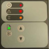
P# |
Category |
Problem |
Q# |
Question |
Yes/ |
C/T |
Solution |
|
|
|
|
|
No |
|
|
|
|
|
|
|
|
|
|
37 |
Firmware |
All of the LEDs in |
- |
- |
- |
C |
The most probable reason for this |
|
|
the scanner’s |
|
|
|
|
situation is that the last firmware |
|
|
front panel are |
|
|
|
|
upgrade attempt was not successful. |
|
|
flashing when you |
|
|
|
|
To remedy this situation, upgrade the |
|
|
turn on the |
|
|
|
|
firmware (see Upgrade Scanner |
|
|
scanner (as |
|
|
|
|
Firmware on page 186). |
|
|
shown in the |
|
|
|
|
NOTE: Before launching the |
|
|
image below), |
|
|
|
|
|
|
|
indicating that |
|
|
|
|
firmware upgrade utility, verify that the |
|
|
printer firmware |
|
|
|
|
scanner is connected directly to the |
|
|
needs to be |
|
|
|
|
touchscreen by the FireWire cable, |
|
|
upgraded. |
|
|
|
|
and then press the rescan bus button. |
|
|
NOTE: This |
|
|
|
|
The scanner will not detect the |
|
|
|
|
|
|
necessary connection without the use |
|
|
|
describes a |
|
|
|
|
of the FireWire. |
|
|
different situation |
|
|
|
|
|
|
|
than when the |
|
|
|
|
|
|
|
scanner is turned |
|
|
|
|
|
|
|
on in special boot |
|
|
|
|
|
|
|
mode, in which |
|
|
|
|
|
|
|
the LEDs also |
|
|
|
|
|
|
|
flash. |
|
|
|
|
|
|
|
|
|
|
|
|
|
Cleaning the Scanning Area
The following parts must be cleaned using a soft lint-free cloth and a mild, streak-free, cleaning detergent. Alternatively, the parts may be cleaned without the use of cleaning detergents by using a damp micro-fibre cleaning cloth (soak the cloth with water and wring until damp):
●Main scanner cover. Clean the main scanner cover to ensure that no dust is introduced into the scanning area when you scan an original.
●White Background Plate on the Guide Plate
●The Glass Plate. If you clean both sides, be very careful not to touch the Stitching Wire (located under the Glass Plate) out of position. Do not use solvents, as this may dissolve the paint used for the black masks on the Glass Plate. Do not recommend that customers clean the underside of the glass plate; it should only be cleaned by an HP support technician.
●The Mirrors. It is necessary to remove the Mirror Chassis to get access to the Mirrors for cleaning. The Camera Adjustment must be checked and if necessary readjusted after the replacement of the Mirror Chassis.
20 Chapter 1 Troubleshooting |
ENWW |
Loading...