


Designjet Z6200 Photo
Table of contents
 Loading...
DESIGNJET Z6200 Photo printer series
Service manual

© 2010 Hewlett-Packard Development
Company, L.P.
1st edition
Legal notices
This document contains proprietary
information that is protected by copyright.
All rights are reserved. No part of this
document may be photocopied, reproduced,
or translated to another language without
the prior written consent of Hewlett-Packard
Company.

Notices
Warranty
The information contained in this
document is subject to change without
notice.
Hewlett-Packard makes no warranty of
any kind with regard to this material,
including, but not limited to, the implied
warranties of merchantability and fitness
for a particular purpose.
Hewlett-Packard shall not be liable for
errors contained herein or for incidental
or consequential damages in connection
with the furnishing, performance, or use
of this material.
WARNING
The procedures described in this manual
are to be performed by HP-qualified
service personnel only.
Electrical shock hazard
Serious shock hazard leading to death
or injury may result if you do not take
the following precautions:
●
Ensure that the ac power outlet
(mains) has a protective earth
(ground) terminal.
●
Disconnect the printer from the
power source prior to performing
any maintenance.
●
Prevent water or any other liquids
from running onto electrical
components or circuits, or through
openings in the enclosure.
Electrostatic discharge
See the beginning of
Service tests and
utilities on page 84 for precautions you
should take to prevent damage to the
printer circuits from electrostatic
discharge.
Safety symbols
General definitions of safety symbols
are given immediately after the table of
contents.
WARNING
The Warning symbol calls attention to a
procedure, practice, or the like, which,
if not correctly performed or adhered to,
could result in personal injury. Do not
proceed beyond a Warning symbol until
the indicated conditions are fully
understood and met.
CAUTION
The Caution symbol calls attention to an
operating procedure, practice, or the
like, which, if not correctly performed or
adhered to, could result in damage to or
destruction of part or all of the product.
Do not proceed beyond a Caution
symbol until the indicated conditions are
fully understood and met.
Customer Assurance
Customer Experience Section
Large Format Printing Division
Hewlett-Packard Española, S.A.
Avenida Graells, 501
08174 Sant Cugat del Vallès
Spain
ENWW iii

iv Notices ENWW

Using this manual
Purpose
This service manual contains information necessary to troubleshoot, test, calibrate and service:
●
HP Designjet Z6200 42-inch Photo printer (Model CQ109A)
●
HP Designjet Z6200 60-inch Photo printer (Model CQ111A)
For information about using these printers, refer to the Using your printer manual.
Readership
The procedures described in this service manual should be performed by HP certified service personnel
only.
Part Numbers
Part numbers for printer options, accessories and service parts can be found in
Parts and diagrams
on page 188.
ENWW v

vi Using this manual ENWW

Table of contents
1 Troubleshooting ................................................................................................................ 1
Printer education and training .................................................................................................... 3
Firmware update ...................................................................................................................... 3
Print-quality troubleshooting ....................................................................................................... 4
Troubleshooting system error codes ............................................................................................ 4
Performing a service test on a failed assembly ............................................................................. 4
Performing the necessary service calibrations .............................................................................. 4
The printer does not power on ................................................................................................... 5
The printer continuously rejects printheads ................................................................................... 5
A new maintenance cartridge is incorrectly detected as ‘used’ ....................................................... 5
Cover sensors are not working ................................................................................................... 5
The Line Sensor has problems detecting paper ............................................................................. 5
Troubleshooting paper jams and printhead crashes ...................................................................... 6
Troubleshooting paper, scan axis and Rewinder Motor shutdown .................................................. 6
Vacuum suction much lower at high altitudes ............................................................................... 8
Banding at variable extreme environmental conditions .................................................................. 8
Printhead crashes/smears on high-density prints using coated paper .............................................. 8
Banding due to ink cartridge replacement while printing ............................................................... 9
34-inch Rice Paper not supported ............................................................................................... 9
Worm marks on HP Coated Paper with light area fills .................................................................. 9
Solving paper-handling problems ............................................................................................... 9
Difficult to load paper: “Too much skew” .................................................................................. 10
Troubleshooting a failure with the Take-Up Reel (TUR) ................................................................. 10
How to read the power switch LEDs .......................................................................................... 13
How to read the Formatter LEDs ............................................................................................... 14
If the front panel turns on and then stops ................................................................................... 16
How to interpret the Service Information Pages .......................................................................... 16
When the main window is open and the printer is printing (safety compliance) .............................. 24
How to troubleshoot the 79:04 system error .............................................................................. 25
2 System error codes ......................................................................................................... 38
What to do if the front panel is blank ....................................................................................... 39
System error codes ................................................................................................................. 39
Explanation of system error codes and warnings ........................................................................ 39
ENWW vii

Continuable and non-continuable error codes ............................................................................ 42
3 Ink supplies .................................................................................................................... 72
What are ink supplies? ........................................................................................................... 73
General information about the ink supplies ................................................................................ 75
General precautions when handling ink supplies ........................................................................ 75
Priming the ink system ............................................................................................................. 76
When should you replace the ink supplies? ............................................................................... 76
Obtaining Ink Cartridge information ......................................................................................... 76
Obtaining Printhead information .............................................................................................. 77
Summary of solving ink supplies problems ................................................................................. 80
Troubleshooting Printhead error codes ...................................................................................... 81
Carriage Interconnect Wiper ................................................................................................... 82
Warranty information for ink supplies ....................................................................................... 82
4 Service tests and utilities ................................................................................................. 84
Introduction ........................................................................................................................... 85
Diagnostics—self test .............................................................................................................. 85
Phone support ........................................................................................................................ 85
Service tests (diagnostics) ........................................................................................................ 85
Entering the Service Tests menu ................................................................................................ 86
Service utilities ..................................................................................................................... 103
5 Service calibrations ....................................................................................................... 123
Service calibrations .............................................................................................................. 124
Entering the Service Calibrations menu ................................................................................... 125
6 Print quality ................................................................................................................. 146
Initial print-quality troubleshooting actions ............................................................................... 147
Troubleshooting tools ............................................................................................................ 148
How to use the Image Quality Service Diagnostic Print ............................................................. 152
Print-quality issues by symptom .............................................................................................. 169
Working with other commercially available papers .................................................................. 184
7 Parts and diagrams ...................................................................................................... 188
Printer support ..................................................................................................................... 189
Center Covers ..................................................................................................................... 190
Electronics Module ............................................................................................................... 191
Right Cover ......................................................................................................................... 192
Left Cover ........................................................................................................................... 193
Right-Hand Assemblies .......................................................................................................... 194
Left-Hand Assemblies ............................................................................................................ 195
Carriage ............................................................................................................................. 196
viii ENWW

Scan-Axis Assemblies ........................................................................................................... 197
Drive Roller and Media-Axis Motor ......................................................................................... 198
Paper Path Assemblies .......................................................................................................... 199
Center Guide and Pinchwheel Assembly ................................................................................. 200
Media Entry Assemblies ........................................................................................................ 201
Take-Up Reel assembly ......................................................................................................... 202
Miscellaneous parts .............................................................................................................. 203
8 Removal and installation .............................................................................................. 205
Service part order ................................................................................................................ 206
Disassembly order ................................................................................................................ 209
9 Preventive maintenance ............................................................................................... 418
Preventive maintenance ........................................................................................................ 419
ENWW ix

x ENWW

1 Troubleshooting
●
Printer education and training on page 3
●
Firmware update on page 3
●
Print-quality troubleshooting on page 4
●
Troubleshooting system error codes on page 4
●
Performing a service test on a failed assembly on page 4
●
Performing the necessary service calibrations on page 4
●
The printer does not power on on page 5
●
The printer continuously rejects printheads on page 5
●
A new maintenance cartridge is incorrectly detected as ‘used’ on page 5
●
Cover sensors are not working on page 5
●
The Line Sensor has problems detecting paper on page 5
●
Troubleshooting paper jams and printhead crashes on page 6
●
Troubleshooting paper, scan axis and Rewinder Motor shutdown on page 6
●
Vacuum suction much lower at high altitudes on page 8
●
Banding at variable extreme environmental conditions on page 8
●
Printhead crashes/smears on high-density prints using coated paper on page 8
●
Banding due to ink cartridge replacement while printing on page 9
●
34-inch Rice Paper not supported on page 9
●
Worm marks on HP Coated Paper with light area fills on page 9
●
Solving paper-handling problems on page 9
●
Difficult to load paper: “Too much skew” on page 10
●
Troubleshooting a failure with the Take-Up Reel (TUR) on page 10
●
How to read the power switch LEDs on page 13
●
How to read the Formatter LEDs on page 14
●
If the front panel turns on and then stops on page 16
ENWW 1
Troubleshooting

●
How to interpret the Service Information Pages on page 16
●
When the main window is open and the printer is printing (safety compliance) on page 24
●
How to troubleshoot the 79:04 system error on page 25
2 Chapter 1 Troubleshooting ENWW
Troubleshooting

Printer education and training
Before any attempt is made to troubleshoot the printer, you must have the relevant training on the HP
Designjet Z6200 Photo printer series. If you are not trained on this printer, please contact HP Education
or HP Training to enquire about becoming ‘HP Service Qualified’ for this printer.
Firmware update
The first step to take when trying to clear an error with the printer is to check that the firmware installed
in the printer is the latest available. Firmware updates often include fixes for common problems, and
simply updating the firmware can often resolve the problem. New firmware can be downloaded here:
http://www.hp.com/go/designjet/downloads
USB firmware update
If it is not possible to perform a firmware update using the Embedded Web Server (for instance, if the
printer has a System Error and the Embedded Web Server is inaccessible), it is still possible to do it
using a USB flash drive.
1. Turn off the printer.
2. Ensure that your USB flash drive contains a valid FMW firmware file and no other files.
3. Connect the USB flash drive to the USB host port on the Formatter.
4. Turn on the printer and follow the instructions on the front panel.
Forced firmware update
When the printer is started for the first time, it may automatically request a firmware update in order to
fix some known issues. You can respond in one of the following ways.
●
Use the USB flash drive provided in the box with the printer.
When a firmware update is requested, you should find a USB flash drive in the box, containing
the new FMW firmware file. Follow the instructions in the flier accompanying the USB flash drive.
NOTE: The USB flash drive is provided only to update the printer's firmware. No other uses of
the USB flash drive are supported.
NOTE: If the USB flash drive is not in the printer box, or fails to work properly, then download
the firmware instead.
●
Download the FWM firmware file from the HP Web site.
Store the file in a standard USB flash drive with no other files. Connect the flash drive to the
formatter's USB host port to perform the firmware update, following the instructions on the front
panel.
●
Skip the firmware update.
If you cannot find the USB flash drive and you have no Internet connection, you can skip the
forced firmware update temporarily by pressing the OK key on the front panel three times, and the
printer will continue with the initialization sequence. Make sure that the firmware update is
performed later. The printer will request the firmware update every time that it starts, until the
update is performed.
ENWW
Printer education and training
3
Troubleshooting

Print-quality troubleshooting
Whenever a print-quality problem appears, it is advisable to print the Diagnostic Print to help diagnose
the problem. The Diagnostic Print will help you differentiate between possible printhead errors and
other problems such as incorrect front-panel selection, driver or RIP configuration or mechanical
problems. For more information on solving print-quality problems, see
Print quality on page 146.
Troubleshooting system error codes
System error codes on page 38 contains a list of system error codes and their respective descriptions
and recommended corrective actions. Try only one recommended action at a time and check whether
the error code has disappeared.
If you have an error code which is not documented in this Service Manual or you have an error which
you cannot resolve, then report the error to the HP Response Center or the nearest HP Support Office.
When reporting the error, have the following information ready:
●
Model and serial number of the printer.
●
Which firmware revision the printer is using (see Note below). Check firmware in Utilities /
Statistics / Code rev.
●
The complete error number.
NOTE: When reporting the system error code, make sure that you supply the full error code and
the firmware version. Without this information, HP support personnel cannot help you.
●
The service configuration print.
●
The current configuration sheet.
●
Which software application the customer is using (name, version, etc.).
Performing a service test on a failed assembly
If possible, always perform a Service Test on the component/assembly that you are about to replace,
just to make sure that is the component/assembly that has failed.
NOTE: If the test on that component/assembly passes, you should NOT replace it.
For information on the Service Tests and how to use them see Service tests and utilities on page 84.
Performing the necessary service calibrations
Is the printer calibrated correctly after replacing a component? For information on the Service
Calibrations and how to use them, see
Service calibrations on page 123.
NOTE: Remember that certain calibrations are required even if an assembly has been disassembled
only to gain access to another assembly or component.
4 Chapter 1 Troubleshooting ENWW
Troubleshooting

The printer does not power on
To resolve printer power-up problems, do the following:
1. Check that the power cord is connected correctly to the printer and to the power socket.
2. Check that the power switch at the rear of the printer is in the on position.
3. Check that the front-panel cable is correctly connected to the Electronics Module. Also make sure
that the front-panel cable is not damaged.
4. Check to see if any of the LEDs on the power switch are on. If any of the LEDs are on, then see
How to read the power switch LEDs on page 13 for more information.
The printer continuously rejects printheads
To resolve printhead rejection problems, do the following:
1. Clean the flex contacts on the Printhead and in the Carriage Assembly using the Carriage
Interconnect Wiper (see
Carriage Interconnect Wiper on page 82) and try again.
2. If all the Printheads are rejected (for each Printhead, the status message on the Front Panel does
not show 'OK') then perform the Carriage Assembly Test
Carriage Assembly test
on page 90..
A new maintenance cartridge is incorrectly detected
as ‘used’
This can occur if the printer has detected the previous Maintenance Cartridge was nearly full, and
when a new Maintenance Cartridge is installed the front panel displays an error that the cartridge is
‘used’. To resolve the problem, manually reset the counter of the Maintenance Cartridge
Reset Life
Counters on page 108.
Cover sensors are not working
To resolve cover sensor problems, do the following:
1. Check whether the sensor cable is damaged or not connected correctly.
2. Replace the faulty sensor.
The Line Sensor has problems detecting paper
To resolve Line Sensor paper detection problems, do the following:
1. Check the type of paper that is being used: the Line sensor may have problems detecting
transparent paper or some types of Non-HP paper. Try loading white HP paper into the printer
and check whether the Line Sensor detects it.
2. Excessive ink deposits on the Platen surface can fool the sensor by reflecting the light. Clean the
Print Platen.
ENWW
The printer does not power on
5
Troubleshooting

3. Clean the Encoder Strip See Clean the Encoder Strip on page 422.
4. The Line Sensor is not calibrated correctly. Perform the Line Sensor Calibration
See Line Sensor
calibration on page 131.
5. The Line Sensor is damaged or faulty. Replace the Line Sensor
See Line Sensor Assembly
on page 353.
Troubleshooting paper jams and printhead crashes
NOTE: If you were using HP Coated Paper when the problem occurred, see also Printhead crashes/
smears on high-density prints using coated paper on page 8.
Paper jams and printhead crashes are grouped together because in many cases a paper jam causes
the paper to lift up into the Carriage path and cause a printhead crash, which means that many paper
jams are reported as printhead crashes.
Question Answer
Did the paper jam occur when loading paper? If paper jams have occurred previously, some pieces of paper
may still be stuck in the paper path. Clear the paper path.
NOTE: Customers often store used rolls without protecting
them from office environmental conditions; when exposed to
high humidity, the paper edges tend to curl. This curling can
cause paper jams when paper is loaded by feeding paper in
without lifting the Media Lever. In these conditions, to avoid
paper jams, the recommendation is to load paper by lifting
the Media Lever and aligning the paper manually, following
the instructions on the front panel.
Is the customer using non-HP paper? The use of non-HP paper can easily be the cause of paper
jams and printhead crashes—especially printhead crashes,
because HP paper is specially formulated to avoid cockle, one
of the primary causes of head crashes. If the paper is not HP-
approved, advise the customer to use HP paper and check to
see if the problem is now solved.
TIP: When clearing a paper jam, sometimes paper is stuck in the paper path. To clear this, you must
lift the Media Lever and insert thicker paper into the paper path to push out the paper that is still stuck
there.
Troubleshooting paper, scan axis and Rewinder
Motor shutdown
If a shutdown occurs, you will get the message “Switch Power Off” followed by one of these messages:
●
Check Maintenance Cartridge Path
●
Check Paper Path
●
Check Printhead Path
NOTE: A shutdown in each path will require different steps to resolve the problem as explained
below. In each case, make sure that you power off the printer before trying to resolve the problem.
6 Chapter 1 Troubleshooting ENWW
Troubleshooting

Also check that the Rewinder Motor moves easily (without friction) with the printer turned off.
Maintenance cartridge path
Open the right door of the printer and check for any visible obstacles restricting the movement of the
Service Station. Manually move the Service Station, checking for smooth and free movement.
Paper path
To resolve paper path problems, do the following:
1. Open the Window and check for any visible obstacles restricting the movement of the Drive Roller.
Make sure that the mylar is not damaged. If there is a wrinkled mass of paper inside the paper
path, lift the Pinch wheels (using the Paper Load Handles) and clear the obstruction.
2. If this shutdown happens at the end of a Roll of Paper, it could be because the paper is stuck
firmly to the Roll. Lift the Pinch wheels (using the Paper Load Handles) and pull the paper clear.
3. Replace the spindle if broken.
4. Perform the Paper Drive Test to obtain further information on the problem
Paper Drive test
on page 87.
Printhead path
When a shutdown occurs in the Printhead path, you will get the message “Switch Power Off / Check
Printhead Path (*). The (*) will be a number, which will give an indication on where the failure
occurred.
PWM shutdown
To resolve a PWM shutdown, do the following:
1. Clean Slider Rods and Apply Oil along the complete axis of the Slider Rods. After applying the
Oil, perform the Scan-Axis Test
See Scan Axis test on page 87 and check that the values are
within the given limits.
2. Clean the Encoder Strip
See Clean the Encoder Strip on page 422.
3. Perform the Scan-Axis Test to obtain further information on the problem
Scan Axis test
on page 87.
Velocity shutdown
To resolve a velocity shutdown, do the following:
1. Open the Window and check for any visible obstacles restricting the movement of the Carriage
Assembly. Try and move the Carriage Assembly manually, checking for smooth and free
movement.
2. Check that the Encoder Strip is clean. If necessary, clean Encoder Strip using a damp cloth.
ENWW
Troubleshooting paper, scan axis and Rewinder Motor shutdown
7
Troubleshooting

Energy shutdown
To resolve an energy shutdown, do the following:
1. Clean Slider Rods and Apply Oil along the complete axis of the Slide Rods. After applying the
Oil, perform the Scan-Axis Test
See Scan Axis test on page 87 and check that the values are
within the given limits.
2. Clean the Encoder Strip
See Clean the Encoder Strip on page 422.
3. Perform the Scan-Axis Test to obtain further information on the problem
Scan Axis test
on page 87.
Vacuum suction much lower at high altitudes
At altitudes above 3,000 meters, the vacuum force holding down the paper will be lower, therefore the
paper will not be held in place properly causing:
●
Ink Smearing on the Paper.
●
Printhead crashes against the Paper.
●
Roll Paper loading problems (low probability).
Banding at variable extreme environmental
conditions
NOTE: This problem is only applicable if the OMAS is disabled.
Since the Accuracy Calibration has been done at normal environmental conditions, printing in extreme
environmental conditions will cause banding because the advance of the Drive Roller does not
correspond to the same conditions that the calibration was done in. To solve the problem, try the
following:
Perform the Accuracy Calibration in the new environmental conditions (see Using your printer).
Printhead crashes/smears on high-density prints
using coated paper
High-density prints can cause cockle mainly on HP Coated Paper. This causes two main problems:
1. Cockling in the borders - Because the printer places too much ink on the Coated Paper, the
borders of the print become raised, causing the Printhead to crash against the paper. To solve the
problem, add a 15 mm white margin to the edges of the images.
2. Cockling within the print - If the printer places too much ink within the print, the paper starts to
ripple, causing the Printhead to smear against the paper. To solve the problem, try the following:
●
Check in the Front Panel if Ink Limiting is ON or OFF. If Ink Limiting is OFF, turn it ON.
●
Avoid using HP Coated Paper for high-density prints. As a substitute, use HP Heavyweight
Coated Paper.
8 Chapter 1 Troubleshooting ENWW
Troubleshooting

Banding due to ink cartridge replacement while
printing
Someone has removed an Ink Cartridge while the printer was printing, which has caused the printer to
stop. If the user does not replace the Ink Cartridge immediately, when the printer starts to print again, a
band will appear in the position where the printing restarted. This is because the wet ink interacts with
the dried ink on the paper causing the band to appear. To solve the problem, try the following:
●
Do not remove an Ink Cartridge while the printer is printing. Only replace/remove Ink Cartridges
between prints.
●
If the Ink Cartridge was replaced due to the “Empty” status on the Front Panel, then advise the
customer to replace the Ink Cartridge when the “Very Low” status is showing on the Front Panel.
●
Reprint the file (without removing the Ink Cartridge).
34-inch Rice Paper not supported
The roll width is 34 inches (non-standard), and the pinch wheels can't control the edge of the paper,
causing ink smears and printhead crashes.
Worm marks on HP Coated Paper with light area
fills
Light bands (S-shaped) in the direction of the media axis when light area fills are printed, causing an
unacceptable print-quality defect.
●
Print the Service Configuration Print and check whether the ambient humidity is very low (below
30%). Increasing humidity may help to reduce the severity of the problem.
NOTE: The paper is causing the problem and not the printer. Do not attempt to replace printer parts
to solve this problem.
Solving paper-handling problems
The front panel keeps indicating that paper Is misaligned or incorrectly positioned.
●
The roll may be loaded the wrong way. The paper should load over the roll toward you.
●
Check that the paper is correctly loaded onto the spindle.
●
The paper may be loaded at an angle. The right-hand edge must be aligned with the blue line on
the Print Platen.
NOTE: Ensure that the paper is wrapped tightly on the roll. This is a very important step to
remember because if this is not done, the paper may be loaded at an angle, causing the paper to
be rejected.
●
The Line Sensor may be malfunctioning. See
The Line Sensor has problems detecting paper
on page 5.
ENWW
Banding due to ink cartridge replacement while printing
9
Troubleshooting

Difficult to load paper: “Too much skew”
If you encounter a high failure rate when loading paper and the Front Panel reports “Too Much Skew”
it is likely that:
●
The encoder strip must be cleaned (this can be carried out by the customer using the User
Maintenance Kit).
●
The Line Sensor must be cleaned.
●
The Blue Line calibration must be performed. See
Platen blue line calibration on page 140.
Troubleshooting a failure with the Take-Up Reel
(TUR)
Use this section to troubleshoot failures with the Take-Up Reel.
Take-Up Reel LED status information
LED status Issue Print job
interrupted
Possible cause Print job interrupted?
Blinking quickly Take-Up Reel not
winding
Yes Sensor beam blocked for
more than 3 seconds
Ensure the Take-Up Reel sensors
are not blocked by a strip of
paper, the collection bin or
other objects.
Also ensure the Take-Up Reel
power switch is in the On
position.
Blinking slowly Take-Up Reel not
winding
No The sensor cables are loose
or unplugged
Ensure the sensor cables are
correctly connected.
Solid red Take-Up Reel not
winding
No There is too much resistance
on the Take-Up Reel motor
ENSURE THAT THE TUR
Spindle Lever is CLOSED!
Ensure the paper is not winding
too tightly. A loop-shaping core
should be inserted and hanging
down.
Solid green Take-Up Reel not
winding
No The Take-Up Reel power
switch is in the Off position
Ensure the Take-Up Reel power
switch is in the On position.
Solid green Take-Up Reel
winding in the
wrong direction,
and not stopping
the job.
No The Take-Up Reel wind
direction switch is in the
wrong winding position.
After 3 seconds, the printer
will recognize the problem
and interrupt the print job. In
this case, see the first error
listed in this table.
Flip the Take-Up Reel wind-
direction switch to the correct
position.
NOTE: If the LED is flashing but there is no message on the front panel, restart the printer.
10 Chapter 1 Troubleshooting ENWW
Troubleshooting
Checking the Take-Up Reel is correctly installed
Many system error codes are displayed as a result of the Take-Up Reel not being installed correctly or
because parts have moved or become dislodged from their correct positions. This troubleshooting
procedure checks the mechanical installation of the Take-Up Reel.
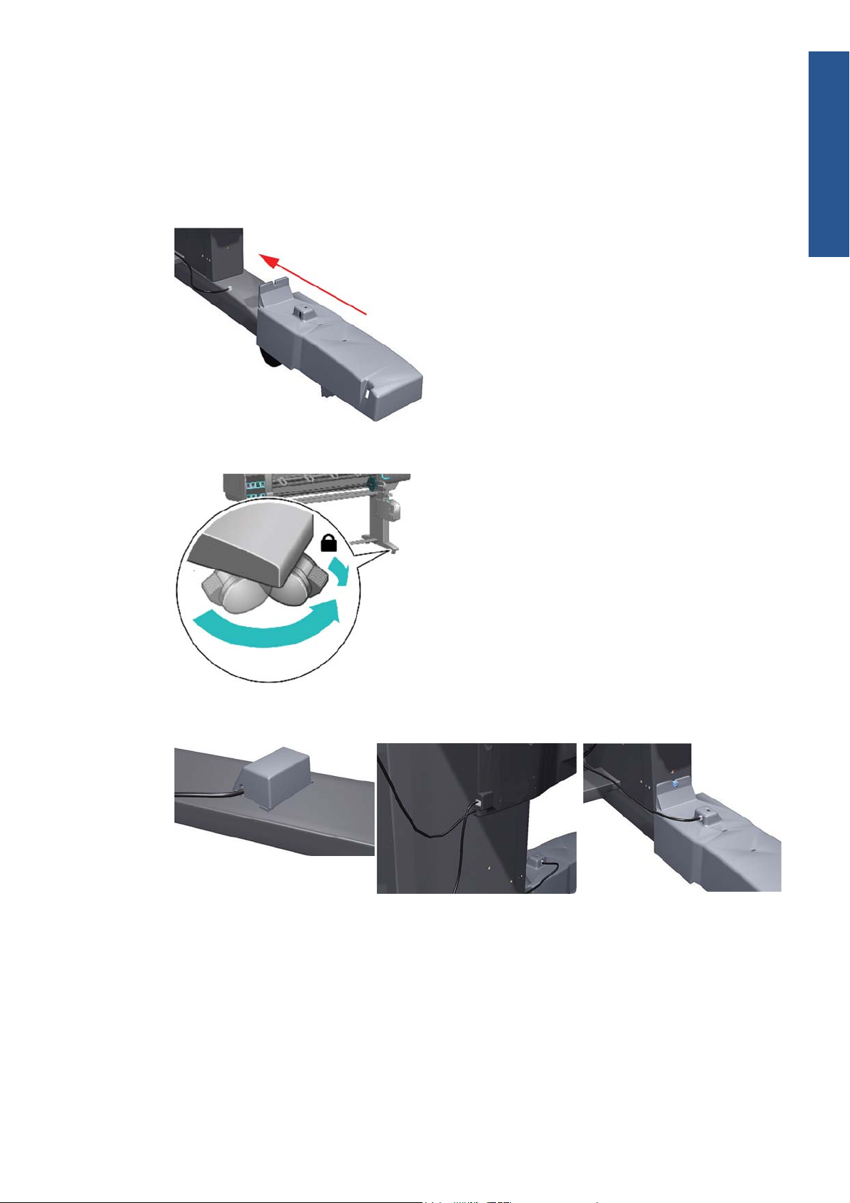
1. Check that the Take-Up Reel sensor unit is correctly installed on the right foot.
2. To correctly install the foot, the wheel has to be positioned as shown.
3. Check the cables linking the sensors to the Take-Up Reel Motor Assembly are correctly connected.
ENWW
Troubleshooting a failure with the Take-Up Reel (TUR)
11
Troubleshooting

4. Check that the Take-Up Reel motor assembly is correctly connected to the rear of the printer.
How the Take-Up Reel works
When selecting the front panel's Paper menu, if there is no line Take-Up Reel installed, this
indicates that the Take-Up Reel has not been enabled at the front panel. This does not mean that the
Take-Up Reel will not work; it just means that, if there is a paper jam detected by the Take-Up Reel,
there will be no warning system error displayed on the front panel. The printer will not stop.
How to install the Take-Up Reel
From the Paper menu > Take-Up Reel > Enable Take-Up Reel. After this is done, you will notice
the following differences:
●
In case of Take-Up Reel Paper jam system error, a warning is reported on the front panel, and the
printer pauses.
●
The cutter is disabled between jobs.
●
When unloading the paper, the front panel will ask you to cut the paper manually.
How it works
When the bottom of the 'loop shaper' is low enough and it cuts the signal between the two sensors, the
Take-Up Reel starts to move the motor until the signal between the two sensors is passing through
again.
If, after a few seconds of turning the Take-Up Reel, the signal between two sensors is still cut, the Take-
Up Reel reports a 'Take-Up Reel paper jam' error:
●
In all cases, the LED of the Take-Up Reel is blinking quickly.
●
If the Take-Up Reel is enabled at the front panel, a Take-Up Reel paper jam will be displayed.
12 Chapter 1 Troubleshooting ENWW
Troubleshooting

How to read the power switch LEDs
In certain circumstances, the LEDs located on top of the power switch (located at the rear of the printer)
indicate the status of power supply to the printer.
1. When only the Amber LED is On:
●
The printer has been switched Off from the Front Panel (after having pressed the On/Off
button).
●
The Power Supply Unit only delivers a 5 V “Standby”; power that is needed to restart the
printer after the Front Panel On/Off button is pressed (the Formatter will start the printer).
2. When the Blue LED is On: Deliver standard “ATX” power for the Electronics Module PCAs
(+12V, +5V, -5V, -12V, etc...). All the functions of the Electronics Module are fully operational
(EWS, etc...).
3. When the Green LED is On: Deliver “analog” 24V and 36V to enable printing.
If you turn on the printer at the front panel, and the Blue LED does not come on, there is a problem.
Turn off the printer using the switch at the rear, then turn it on again using the same switch. If the Blue
LED still does not come on, replace the Power Supply Unit.
If the Blue LED comes on this time, you will probably see an error reported on the front panel as the
printer starts up. If no error is reported, but you continue to have problems when turning on the printer
from the front panel, see
How to read the Formatter LEDs on page 14.
ENWW
How to read the power switch LEDs
13
Troubleshooting
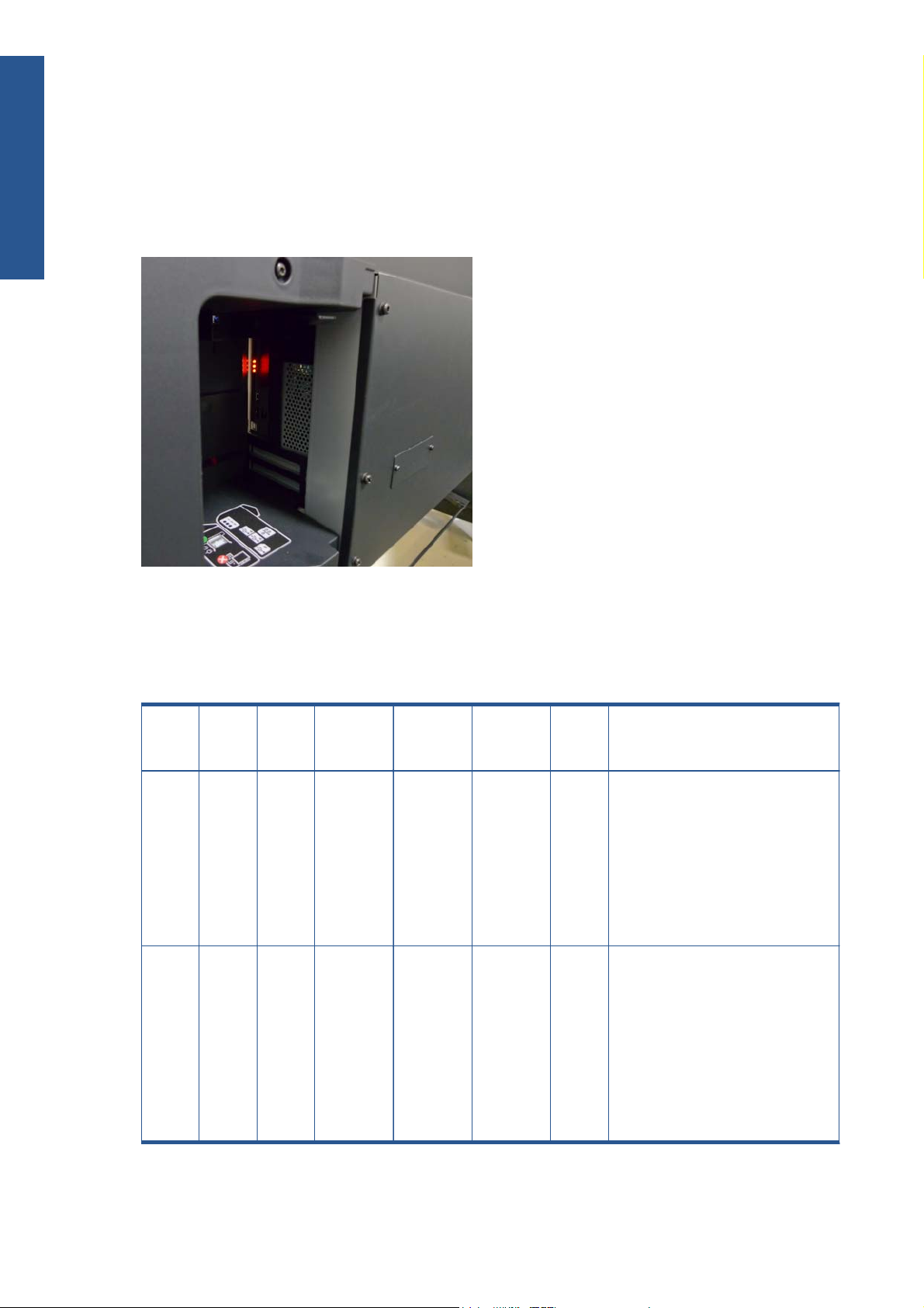
How to read the Formatter LEDs
The LEDs located on the Formatter can help to troubleshoot the printer. The LEDs can either be on or off;
different combinations can indicate different problems.
The following image shows the three Formatter LEDs, which are numbered from the top down: number I
at the top, number II in the middle, number III at the bottom.
Use the following table to interpret the LEDs and find the source of the problem. Remember that you
should read these LEDs when you push the Power button.
Some combinations may require you to replace two or more components. In this case, always replace
one component at a time. Test the printer to see if the problem has disappeared (check the LEDs again).
If the same LED sequence continues, replace the next component indicated in the table.
Power
amber
LED
Power
blue
LED
Power
green
LED
Formatter
I LED
Formatter
II LED
Formatter
III LED
Front
panel
status
Problem and recommendations
Off Off Off Off Off Off Off The printer is not receiving electrical
power.
1. Ensure that the printer is connected
to the power outlet.
2. Ensure that the outlet delivers the
expected power.
3. Replace the Power Supply Unit.
On Off Off Off Off Off Off The Power key fails to turn on the
printer.
1. Turn the printer off using the switch
at the rear, and disconnect the
power cord. Reconnect the power
cord and turn on the printer using
the switch at the rear.
2. If the problem persists, replace the
Front Panel.
14 Chapter 1 Troubleshooting ENWW
Troubleshooting

Power
amber
LED
Power
blue
LED
Power
green
LED
Formatter
I LED
Formatter
II LED
Formatter
III LED
Front
panel
status
Problem and recommendations
Off On Off Off Off Off Off There is a power failure in the
Formatter.
1. Reseat the power connector in the
Formatter, and remove the
Formatter.
2. Turn the printer on again.
3. If the problem persists, replace the
Power Supply Unit.
4. If the problem persists, replace the
Formatter.
5. If the boot process starts, replace
the Formatter.
Off On Off On Off Off Off The Formatter BIOS is unable to start.
If an external Memory Module is
installed:
1. Reseat the Memory Module.
2. Remove the Memory Module and
restart the printer.
3. If the printer is able to start
normally, replace the Memory
Module. If not, replace the
Formatter.
If an external Memory Module is not
installed, replace the Formatter.
Off On Off Flashing Off Off Off The Formatter BIOS cannot detect the
Hard Disk Drive.
1. Reseat the Hard Disk Drive
connectors.
2. Replace the Hard Disk Drive.
Off On Off On Flashing Off Off The operating system has experienced a
fatal error. Replace the Hard Disk Drive.
Off On Off On On Off Off There is a communication failure in the
Formatter.
1. Reseat the Formatter.
2. Replace the Formatter.
Off On Off On On Flashing Off There is an initialization failure in the
Formatter. Replace the Formatter.
Off On Off On On On Off There is an initialization failure in the
Front Panel.
1. Reseat the Front Panel cable.
2. Replace the Front Panel.
ENWW
How to read the Formatter LEDs
15
Troubleshooting

If the front panel turns on and then stops
If the power-up process stops while the front panel is displaying a number, respond as follows.
1. If the printer's Power-Up process stops when the front panel is displaying the number 17, this
indicates that there is a problem with the file system on the printer's Hard Disk Drive, so the printer
is checking the whole file system and making any necessary corrections. This problem can arise
when there has been a power cut while the printer was switched On, or if there is a physical
problem with the Hard Disk Drive.
Checking the whole file system normally takes about half an hour (but could take much longer).
There is nothing that can be done to speed up the file checking process. If you turn Off the printer
during the checking process, the file system check will restart whenever you turn it On again
If you experience this problem repeatedly when there has been no power cut, then this could
mean that the Hard Disk Drive is faulty. In this case, replace the Hard Disk Drive
See Hard Disk
Drive (HDD) on page 340.
2. If the printer's start-up process stops when the front panel is displaying any other number between
1 and 30, then try the following:
●
Turn the power off at the rear of the printer and disconnect the power cord. Reconnect the
power cord and turn on the printer.
●
If the printer continues to stop during the power-up process, replace the Hard Disk Drive
See Hard Disk Drive (HDD) on page 340.
How to interpret the Service Information Pages
The Service Information Pages contain the following information:
●
Current Configuration
●
Current Information
●
Usage Information
●
Event Logs
●
Calibration Status
●
Connectivity Configuration
●
All Pages
It is possible to print the Service Information Pages either through the Front Panel or through the
Embedded Web Server:
●
Front Panel:
icon > Service information prints.
16 Chapter 1 Troubleshooting ENWW
Troubleshooting

●
Embedded Web Server: Support tab > Service support > Printer information.
Even if the printer cannot print, the Information Pages are still accessible through the Embedded Web
Server.
Main characteristics
●
Only available in English (except the current information page).
●
From the Front Panel, you can choose to print ALL pages or just select the specific pages that are
needed. If ALL pages are printed:
◦
Nesting is turned ON automatically (and turned OFF once all the pages have been printed).
◦
Nesting cannot be mixed with other jobs in the queue.
●
Each page can be printed from the Web browser when using the Embedded Web Server.
●
Each page can be sent by e-mail from the Web Browser when using the Embedded Web Server
(File ⇒ Send ⇒ Page by E-mail).
●
You can see the same information through the Front Panel or the Embedded Web Server.
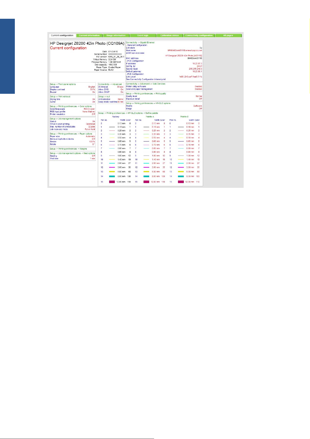
Current configuration
This page contains full details of the current configuration of the printer.
ENWW
How to interpret the Service Information Pages
17
Troubleshooting
Current information
This page contains the following information:
●
Current Printer Configuration
●
Paper Loaded Information
●
Current Printhead Kit Information
●
Current Ink Cartridge Information
18 Chapter 1 Troubleshooting ENWW
Troubleshooting
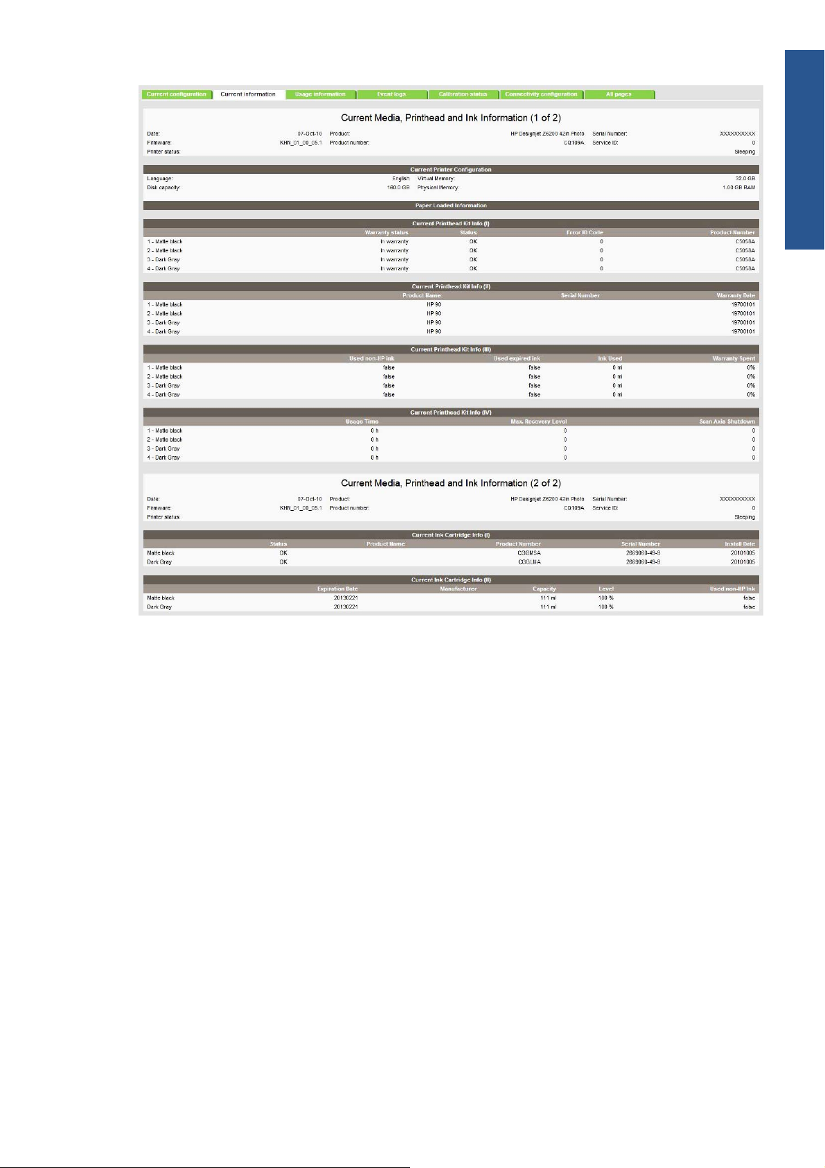
The first two lines are available at the beginning of each Service Information Page and contains
standard information (like Service ID, firmware version).
Printer usage information
This page contains the following information:
●
Printer Usage
●
Usage per Printhead Slot
●
Usage per Cartridge Slot
●
Media Usage per Paper Type
●
Component Usage
●
Spittoon Usage
●
Preventive Maintenance Usage
ENWW
How to interpret the Service Information Pages
19
Troubleshooting
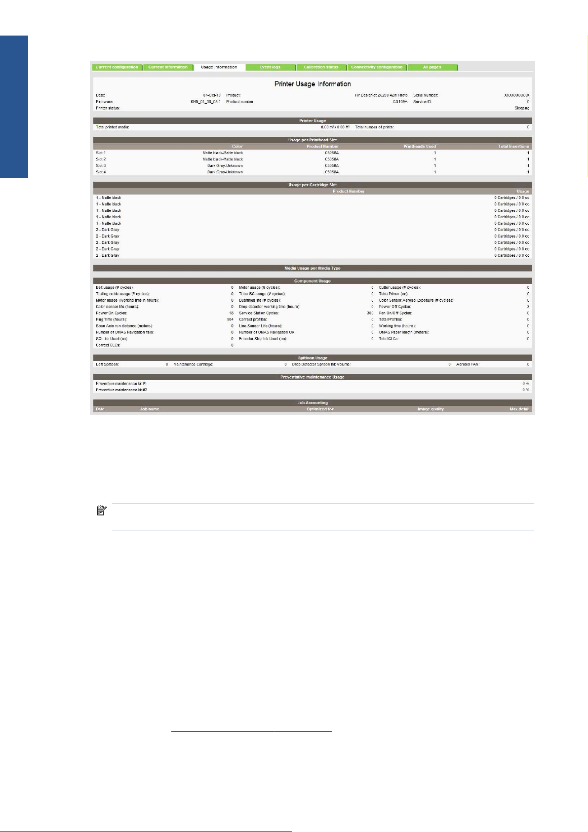
Media used sections
●
Total media used in the printer
●
Media used for each media type
NOTE: If the Hard Disk Drive is replaced, the media used for each media type will be set to
zero.
Printhead section
The Printheads section displays the Printhead usage per slot.
●
Total Insertions: This is linked with the crane of the Ink Supply Tubes. When the Ink Supply
Tubes are replaced, the total insertions will be reset to zero.
Cartridge section
The Ink Cartridges section displays the ink usage per cartridge.
Preventive maintenance section
Once the value reaches 100%, the corresponding Preventive Maintenance Kit should be used. For
further details, see
Preventive maintenance on page 418.
20 Chapter 1 Troubleshooting ENWW
Troubleshooting
Loading...