


Removal and Installation
Screw Types 8-4
Left Hand Cover 8-5
Right Hand Cover 8-7
Front Panel 8-9
Window and Top Cover 8-10
Media Deflectors 8-11
Left End Roll-Feed 8-13
Right End Roll-Feed 8-15
Back Platen 8-17
Media Sensor 8-19
Formatter 8-20
LAN Card 8-21
Spittoon 8-23
Electronics Module 8-24
Power Supply 8-27
Scan-Axis Motor Assembly 8-29
Cutter Assembly 8-32
Left Encoder Holder 8-33
Cutter Bushing 8-35
Cutter Guide Bracket 8-36
Drive Roller Encoder Sensor 8-38
Trailing Cable 8-40
Ink Supply Station 8-48
Interconnect PCA 8-50
Service Station and Aerosol Fan 8-52
Cutter Guide 8-55
Print Platen 8-56
Service Station Holder 8-57
Interconnect Cable 8-59
Ink Supply Tubes 8-60
Vacuum Fan 8-64
Pinch-Arm 8-66
Pinch-Arm Mechanism 8-67
Pinch-Arm Lever 8-69
Pinch-Arm Sensor 8-71
Fork Idler, Tensioner and Idler Pulley 8-74
Encoder Strip 8-76
Carriage Assembly (Including Belt) 8-78
Paper-Axis Motor 8-84
Drive Roller 8-86
Gear Assemblies 8-92
HP DesignJets 500 and 800 Series Printers Service Manual |
8-1 |

Removal and Installation
Introduction
This chapter is a step by step guide to the removal and installation of the key components in the printer. You may find it useful to tick off the steps as they are performed. Use the illustration at each procedure to identify the parts referred to in the text.
The procedures appear in order of removal. So the whole machine can be stripped down by starting at the beginning of this chapter and working through the subsequent procedures.
NOTE |
Before using this chapter to remove and install a new component, |
|
always make sure that you have performed the relevant service |
|
test from Chapter 4. If the test passes you will not need to replace |
|
the component. |
|
|
Safety Precautions
Review WARNING and CAUTION symbols and instructions before you service the printer. Follow these warnings and cautions for your protection and to avoid damaging the printer.
WARNING |
Serious shock hazard leading to death or injury may result if you |
|
do not take the following precautions: |
|
Ensure that the ac power outlet (mains) has a protective earth |
|
(ground) terminal. |
|
Switch the plotter off, and disconnect it from the power source |
|
prior to performing any maintenance. |
|
Prevent water or other liquids from running onto electrical |
|
components or circuits, or through openings in the module. |
|
|
8-2 |
HP DesignJets 500 and 800 Series Printers Service Manual |

Removal and Installation
Electrostatic Discharge (ESD) Precautions
To prevent damage to the Printer circuits from high-voltage electrostatic discharge (ESD):
1.Do not wear clothing that is subject to static build-up.
2.Do not handle integrated circuits (ICs) in carpeted areas.
3.Do not remove an IC or a printed circuit assembly (PCA) from its conductive foam pad or conductive packaging until you are ready to install it.
4.Ground (earth) your body while disassembling and working on the Printer.
5.After removing a cover from the Printer, attach an earthing (ground) lead between the PCA common and earth ground. Touch all tools to earth ground to remove static charges before using them on the Printer.
6.After removing any PCA from the Printer, place it on a conductive foam pad or into its conductive packaging to prevent ESD damage to any ICs on the PCA.
Required Tools
The following tools are required to disassemble and repair the Printer.
Long Torx Screwdriver with the indicated attachments
Nut driver with the indicated attachments
Small flat-blade screwdriver
HP DesignJets 500 and 800 Series Printers Service Manual |
8-3 |

Removal and Installation
Screw Types
Type |
Torx |
Length |
Head Type |
Thread Type |
Part Number |
|
|
(mm) |
|
|
|
|
|
|
|
|
|
|
|
|
|
|
|
A |
T-20 |
17 |
Pan |
Taptite |
0515-1743 |
|
|
|
|
|
|
B |
T-10 |
8.0 |
Pan |
Taptite |
0515-2200 |
|
|
|
|
|
|
C |
T-20 |
10 |
Pan |
Taptite |
0515-2282 |
|
|
|
|
|
|
D |
T-10 |
17.5 |
Pan Washer |
Plastite |
0515-2675 |
|
|
|
|
|
|
E |
T-15 |
12.7 |
Pan |
Plastite |
0624-0769 |
|
|
|
|
|
|
F |
T-15 |
20 |
Pan |
Plastite |
0624-0771 |
|
|
|
|
|
|
G |
T-8 |
12.7 |
Pan |
Plastite |
0624-0768 |
|
|
|
|
|
|
H |
T-20 |
35 |
Pan |
Taptite |
0515-2521 |
|
|
|
|
|
|
I |
T-15 |
9.5 |
Pan |
Plastite |
0515-2981 |
|
|
|
|
|
|
J |
T-10 |
8 |
Pan |
Machined |
0515-2246 |
|
|
|
|
|
|
8-4 |
HP DesignJets 500 and 800 Series Printers Service Manual |

|
|
Removal and Installation |
|
|
|
Left Hand Cover |
|
|
Removal |
|
|
|
|
|
WARNING |
Switch off the printer and remove the power cable. |
|
|
Refer to the table on Page 8-4 for information on screw types. |
|
|
||
NOTE |
||
|
1. |
Remove the Spindle. |
|
||
|
2. |
Remove 3 T-20 screws (Type F) from |
|
|
the Rear of the Left Hand Cover. |
3. Remove the LAN Card Cover from the back of the Left Hand Cover.
HP DesignJets 500 and 800 Series Printers Service Manual |
8-5 |
Removal and Installation
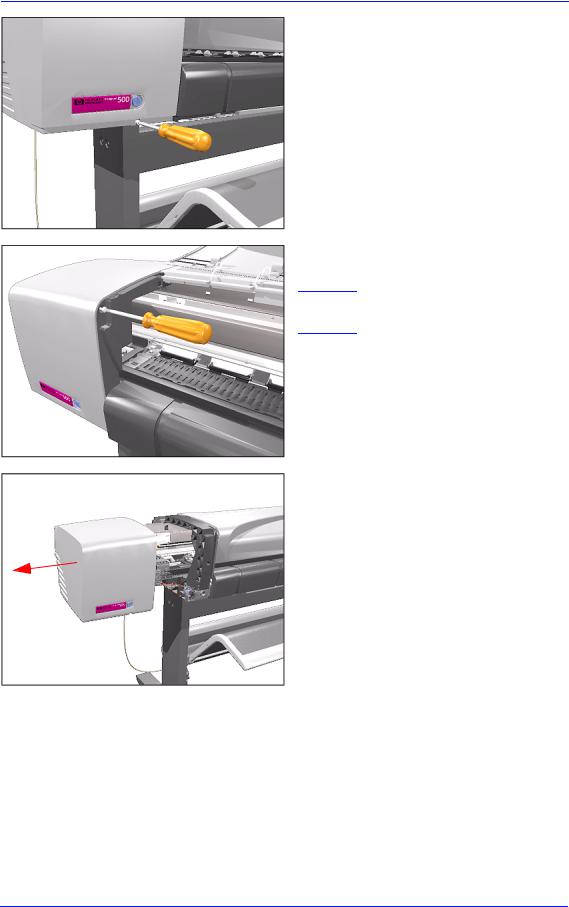
4. Remove 1 T-20 screw (Type F) from the front of Left Hand Cover.
5. Open the Window and remove 1 T-20 screw (Type F) from the side-plate.
NOTE Be careful not to drop the screw into the Printer.
6. Remove the Left Hand Cover.
8-6 |
HP DesignJets 500 and 800 Series Printers Service Manual |

|
Removal and Installation |
|
|
Right Hand Cover |
|
Removal |
|
|
|
WARNING |
Switch off the printer and remove the power cable. |
|
Refer to the table on Page 8-4 for information on screw types. |
|
|
NOTE |
|
|
|
1. Remove 1 T-20 screw (Type F) from the back of the Right Hand Cover.
2. Open the Ink Cartridge Door and remove 1 T-20 screw (Type F) from the back of the Right Hand Cover.
3. Keep the Ink Cartridge Door open and remove 1 T-20 screw (Type F) from the top of the Right Hand Cover.
HP DesignJets 500 and 800 Series Printers Service Manual |
8-7 |

Removal and Installation
4. Remove 1 T-20 screw (Type F) from the front of the Right Hand Cover.
5. Open the Window and remove 1 T-20 screw (Type F) from the side plate.
6. Remove the Right Hand Cover.
NOTE Always keep the Ink Cartridge door open when removing/installing the Right Hand Cover.
8-8 |
HP DesignJets 500 and 800 Series Printers Service Manual |

|
|
|
Removal and Installation |
|
|
|
|
Front Panel |
|
|
|
Removal |
|
|
|
|
|
|
|
WARNING |
Switch off the printer and remove the power cable. |
||
|
1. |
Remove the the Right Hand Cover - |
|
|
|||
|
|
|
Refer to Page 8-7. |
|
2. |
Remove the Right Hand Trim. |
|
|
2 |
|
|
|
|
|
|
|
|
|
|
1
Disconnect |
3. Disconnect Front Panel Connector |
|
from the ISS PCA. |
||
|
4. Unclip the Front Panel and remove from the Printer.
1
2
HP DesignJets 500 and 800 Series Printers Service Manual |
8-9 |

Removal and Installation
Window and Top Cover
Removal
WARNING |
Switch off the printer and remove the power cord. |
|
Refer to the table on Page 8-4 for information on screw types. |
NOTE |
|
|
1. Remove the following screws |
|
|
|
(Type A) from the rear that attach the |
|
Top Cover to the Printer: |
|
ν 2 T-20 screws for the 24" model. |
|
ν 3 T-20 screws for the 42" model. |
2. Raise Window and unclip at both ends.
3. Lift up complete assembly (Window and Top Cover) and remove from Printer.
8-10 |
HP DesignJets 500 and 800 Series Printers Service Manual |
Removal and Installation
Media Deflectors
Removal
WARNING |
Switch off the printer and remove the power cord. |
1. Make sure the Media Lever is in the UP Position.
2. Lift tab up and slide Right Deflector
1 |
to the left and lift up. |
|
2
3
HP DesignJets 500 and 800 Series Printers Service Manual |
8-11 |

Removal and Installation
3. Lift tab up and slide Middle Deflector to the right and lift up.
3
2
1
4. Lift tab up and slide Left Deflector to the right and lift up.
3
2
1 
8-12 |
HP DesignJets 500 and 800 Series Printers Service Manual |

Removal and Installation
Left End Roll-Feed
Removal
WARNING |
Switch off the printer and remove the power cord. |
|
|
Refer to the table on Page 8-4 for information on screw types. |
|
NOTE |
||
|
1. |
Remove the Left Hand Cover - Refer |
|
||
|
|
to Page 8-5 |
|
2. |
Remove the Spindle. |
|
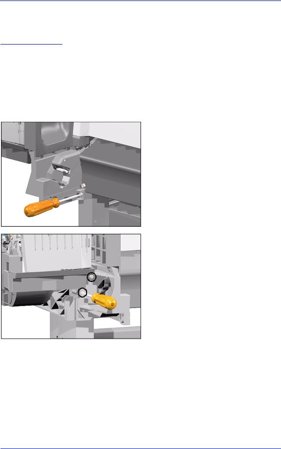
3. |
Remove 1 T-20 screw (Type F) from |
|
|
the Left Hand Roll-Feed (located on |
|
|
the inside next to the Electronics |
|
|
Module). |
4. Remove 2 T-20 screws (Type F) from the Left End Roll-Feed.
HP DesignJets 500 and 800 Series Printers Service Manual |
8-13 |

Removal and Installation
5. Move Left End Roll-Feed down and remove from Printer.
8-14 |
HP DesignJets 500 and 800 Series Printers Service Manual |
Removal and Installation
Right End Roll-Feed
Removal
WARNING |
Switch off the printer and remove the power cord. |
|
|
Refer to the table on Page 8-4 for information on screw types. |
|
NOTE |
||
|
1. |
Remove the Right Hand Cover - Refer |
|
||
|
|
to Page 8-7. |
|
2. |
Remove the Spindle. |
|
3. |
Remove 1 T-20 screw (Type F) from |
|
|
the Right Hand Roll-Feed. |
4. Remove 2 T-20 screws (Type F) from the Right Hand Roll-Feed (located on the inside).
HP DesignJets 500 and 800 Series Printers Service Manual |
8-15 |

Removal and Installation
5. Remove Right Hand Roll-Feed.
8-16 |
HP DesignJets 500 and 800 Series Printers Service Manual |

Removal and Installation
Back Platen
Removal
WARNING
NOTE
Switch off the printer and remove the power cord.
Refer to the table on Page 8-4 for information on screw types.
1.Remove the Spindle.
2.Make sure the Media Lever is in the UP Position.
3.Unclip the Media Sensor Cover and remove from the Printer.
|
|
|
|
|
|
|
|
|
|
HP DesignJets 500 and 800 Series Printers Service Manual |
8-17 |
|||

Removal and Installation
4. Unclip the Media Sensor from underneath the Back Platen.
5. Remove 2 T-15 screws (Type E) from the Back Platen.
6. Remove the Back Platen by pulling it evenly towards you.
NOTE Make sure that the Media Sensor is not attached to the Back Platen to prevent pulling the cable and breaking the sensor.
8-18 |
HP DesignJets 500 and 800 Series Printers Service Manual |

Removal and Installation
Media Sensor
Removal
WARNING |
Switch off the printer and remove the power cord. |
|
|
1. |
Remove the Right Hand Cover - Refer |
|
|
to Page 8-7. |
|
2. |
Remove the Spindle. |
|
3. |
Disconnect the Media Sensor Cable |
|
|
from the ISS PCA. |
4. Unclip the Media Sensor Cover and remove from the Printer.
5. Unclip the Media Sensor from underneath the Back Platen. Route the Media Sensor cable out where necessary and remove the Media Sensor.
|
|
|
|
|
|
|
|
|
|
HP DesignJets 500 and 800 Series Printers Service Manual |
8-19 |
|||

Removal and Installation
Formatter
Removal
WARNING |
Switch off the printer and remove the power cord. |
|
1. Remove the LAN Card Cover from |
|
the back of the Left Hand Cover. |
2. With a flat end screwdriver, unscrew the 2 screws that attach the Formatter to the Electronics.
3. Remove the Formatter.
8-20 |
HP DesignJets 500 and 800 Series Printers Service Manual |
|
Removal and Installation |
|
|
LAN Card |
|
Removal |
|
|
|
WARNING |
Switch off the printer and remove the power cord. |
|
1. Remove the LAN Card Cover from |
|
|
|
the back of the Left Hand Cover. |
2. Disconnect the LAN Cable from the LAN Card
3. With a flat end screwdriver, unscrew the 2 screws that attach the LAN Card to the Electronics.
HP DesignJets 500 and 800 Series Printers Service Manual |
8-21 |

Removal and Installation
4. Remove the LAN Card from the Printer.
8-22 |
HP DesignJets 500 and 800 Series Printers Service Manual |

|
|
|
Removal and Installation |
|
|
|
|
Spittoon |
|
|
|
Removal |
|
|
|
|
|
|
|
WARNING |
|
Switch off the printer and remove the power cord. |
|
|
|
|
|
|
1. |
Remove the Left Hand Cover - Refer |
|
|
|
|
to Page 8-5. |
|
2. |
Release the cables that are attached to |
|
|
Release |
the Spittoon. |
|
|
|
||
3. Press in the 2 clips to release the Spittoon.
4. Lift up the Spittoon and remove from the Printer.
|
|
|
|
|
|
|
|
|
|
HP DesignJets 500 and 800 Series Printers Service Manual |
8-23 |
|||

Removal and Installation
Electronics Module
Removal
WARNING |
Switch off the printer and remove the power cord. |
|
|
Refer to the table on Page 8-4 for information on screw types. |
|
NOTE |
||
|
1. |
Remove the Left Hand Cover - Refer |
|
||
|
|
to Page 8-5. |
|
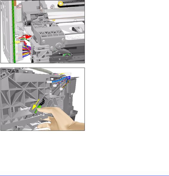
2. |
Disconnect ALL the cables from the |
|
|
Electronics Module. |
Disconnect
3. Remove 1 T-10 screw (Type B) from the top of the Electronics Module.
8-24 |
HP DesignJets 500 and 800 Series Printers Service Manual |

Removal and Installation
4.Remove 1 T-10 screw (Type B) from the back of the Electronics Module.
5.Loosen 1 T-10 screw (Type B) just below the Electronics Module.
Loosen Only
|
|
6. Lift the Electronics Module up and |
|
|
towards the right and remove from |
|
|
|
2 |
Printer. |
|
1
HP DesignJets 500 and 800 Series Printers Service Manual |
8-25 |

Removal and Installation
Installing the Electronics Module
NOTE |
When |
installing |
the |
|
Electronics |
Module, |
make |
sure that you insert the tab on the Printer into the slot in the Electronics Module.
8-26 |
HP DesignJets 500 and 800 Series Printers Service Manual |

Removal and Installation
Power Supply
Removal
WARNING
NOTE
Switch off the printer and remove the power cord.
Refer to the table on Page 8-4 for information on screw types.
1.Remove the Left Hand Cover - Refer to Page 8-5.
2.Remove 1 T-10 (Type B) screw from the Power Switch on the front of the Printer.
3. Disconnect the Power Supply Cable
from the Electronics Module.
Disconnect
HP DesignJets 500 and 800 Series Printers Service Manual |
8-27 |

Removal and Installation
4. Remove 2 T-10 screws (Type B) that secure Power Supply to the Bracket.
5. Remove the Power Supply as one assembly (Power Switch and Power Supply Unit).
 3
3
1
2
8-28 |
HP DesignJets 500 and 800 Series Printers Service Manual |
|
|
Removal and Installation |
|
|
|
Scan-Axis Motor Assembly |
|
|
Removal |
|
|
|
|
|
WARNING |
Switch off the printer and remove the power cord. |
|
|
Refer to the table on Page 8-4 for information on screw types. |
|
|
||
NOTE |
||
|
1. |
Remove the Left Hand Cover - Refer |
|
||
|
|
to Page 8-5. |
|
2. |
Remove the Right Hand Cover - Refer |
|
|
to Page 8-7. |
|
3. |
Remove the Power Supply - Refer to |
|
|
Page 8-27. |
|
4. |
Disconnect the Scan-Axis Motor |
|
|
Cable from the Electronics Module. |
5. Release the tension from the right hand side of the Belt by pulling the Tensioner down and pushing it towards you to lock it into position.
HP DesignJets 500 and 800 Series Printers Service Manual |
8-29 |
 Loading...