


 Loading...
Removal and Installation
Screw Types 8-4
Top Cover Assembly 8-5
Left Hand Cover 8-6
Right Hand Cover 8-10
Front Panel Assembly 8-14
Left Rear Cover 8-15
Right Rear Cover 8-16
Extension Cover (60" Model only) 8-17
Media Lever Assembly 8-18
Right Hand Trim 8-20
Left Hand Trim 8-22
Back Cover 8-23
Ink Tubes System 8-25
EMC Covers 8-32
Encoder Strip 8-34
Trailing Cable 8-36
Tensioner Assembly 8-42
Carriage Assembly and Belt 8-46
Line Sensor 8-53
Scan-Axis Motor 8-57
Cutter Assembly 8-60
Ink Supply Station (ISS) 8-64
Air Pressurization System (APS) 8-67
Service Station Assembly 8-69
Drop Detector Assembly 8-72
Hard Disk Drive (HDD) 8-74
LAN Card 8-76
Memory and BootROM DIMM’s 8-77
Electronics Module Cover 8-79
Main PCA 8-81
PCI-to-IDE PCA 8-85
Power Supply Unit (PSU) 8-88
Ink Supply Station (ISS) PCA 8-91
Ink Leak Detector - If Present (Only Applicable to the 5000 Series) 8-93
Cooling Fans 8-95
Electronics Module (as one complete Assembly) 8-97
Pinch-Wheels 8-98
Pinch-Wheel Cam 8-100
Vacuum Fan 8-103
Paper-Axis Motor Assembly 8-105
Booster Fan 8-108
Media Sensor 8-109
Entry Roller 8-111
Center Guide Assembly 8-112
Drive Roller Gear 8-114
Front Platen Assembly (Only Applicable to the 5000 Series) 8-115
Center Platen Assembly 8-117
Deflectors (Only Applicable to the 5000 Series) 8-119
Heater Assembly (Only Applicable to the 5500 Series) 8-120
Tube Guide Door 8-124
HP DesignJet 5000 and 5500 Series Printers Service Manual |
8-1 |

Removal and Installation
Introduction
This chapter is a step by step guide to the removal and installation of the key components in the Printer. You may find it useful to tick off the steps as they are performed. Use the illustration at each procedure to identify the parts referred to in the text.
The procedures appear in order of removal. So the whole machine can be stripped down by starting at the beginning of this chapter and working through the subsequent procedures.
NOTE
THE INSTRUCTIONS IN THIS CHAPTER APPLY BOTH TO THE DESIGNJET 5000 AND 5500 SERIES UNLESS OTHERWISE NOTED. EVEN THOUGH THE ILLUSTRATIONS ARE SHOWN USING THE DESIGNJET 5000 SERIES, THESE ARE ALSO APPLICABLE TO THE DESIGNJET 5500 SERIES.
NOTE
Before using this chapter to remove and/or replace a component or assembly, always make sure that you have performed the relevant service test for each component as described in 4, Service Tests and Utilities. If the test passes you will not need to replace the component.
NOTE
NOTE
To install a component perform the removal procedures in reverse order unless a specific installation procedure is provided.
After removing and/or replacing a component, the relative procedure will state whether any calibrations and/or tests are required (Chapter 5, Service Calibrations).
Safety Precautions
(Safety symbols - Immediately after the table of contents.)
Review WARNING and CAUTION symbols and instructions before you service the Printer. Follow these warnings and cautions for your protection and to avoid damaging the Printer.
WARNING |
Serious shock hazard leading to death or injury may result if you |
|
do not take the following precautions: |
|
Ensure that the ac power outlet (mains) has a protective earth |
|
(ground) terminal. |
|
Switch the printer off, and disconnect it from the power source |
|
prior to performing any maintenance. |
|
Prevent water or other liquids from running onto electrical |
|
components or circuits, or through openings in the module. |
|
|
8-2 |
HP DesignJet 5000 and 5500 Series Printers Service Manual |

Removal and Installation
Electrostatic Discharge (ESD) Precautions
To prevent damage to the Printer circuits from high-voltage electrostatic discharge (ESD):
1.Do not wear clothing that is subject to static build-up.
2.Do not handle integrated circuits (ICs) in carpeted areas.
3.Do not remove an IC or a printed circuit assembly (PCA) from its conductive foam pad or conductive packaging until you are ready to install it.
4.Ground (earth) your body while disassembling and working on the Printer.
5.After removing a cover from the Printer, attach an earthing (ground) lead between the PCA common and earth ground. Touch all tools to earth ground to remove static charges before using them on the Printer.
6.After removing any PCA from the Printer, place it on a conductive foam pad or into its conductive packaging to prevent ESD damage to any ICs on the PCA.
Required Tools
The following tools are required to disassemble and repair the Printer.
Long Torx Screwdriver with the indicated attachments
T8 T10 T15 T20 T25
Nut driver with the indicated attachments
Small flat-blade screwdriver
HP DesignJet 5000 and 5500 Series Printers Service Manual |
8-3 |

Removal and Installation
Screw Types
WARNING |
|
Chassis screws have a copper washer and should never be |
||||||
|
|
|
removed. |
|
|
|
|
|
|
|
|
|
|
|
|
|
|
|
|
|
|
|
|
|
|
|
Type |
|
Torx |
|
Length |
Head Type |
Thread Type |
Part Number |
|
|
|
|
|
|
(mm) |
|
|
|
|
|
|
|
|
|
|
|
|
|
|
|
|
|
|
|
|
|
A |
|
T-20 |
|
17 |
Pan |
Taptite |
0515-1743 |
|
|
|
|
|
|
|
|
|
|
B |
|
T-15 |
|
12 |
Pan |
Machined |
0515-0382 |
|
|
|
|
|
|
|
|
|
|
C |
|
T-20 |
|
10 |
Pan |
Taptite |
0515-2282 |
|
|
|
|
|
|
|
|
|
|
D |
|
T-15 |
|
12.5 |
Pan Washer |
Plastite |
0515-3040 |
|
|
|
|
|
|
|
|
|
|
E |
|
T-15 |
|
12.7 |
Pan |
Plastite |
0624-0769 |
|
|
|
|
|
|
|
|
|
|
F |
|
T-15 |
|
20 |
Pan |
Plastite |
0624-0771 |
|
|
|
|
|
|
|
|
|
|
G |
|
T-8 |
|
12.7 |
Pan |
Plastite |
0624-0768 |
|
|
|
|
|
|
|
|
|
|
H |
|
T-15 |
|
9.5 |
Pan |
Plastite |
0515-2981 |
|
|
|
|
|
|
|
|
|
|
I |
|
T-10 |
|
7.5 |
Flat |
Taptite |
0515-2984 |
|
|
|
|
|
|
|
|
|
|
J |
|
T-15 |
|
27.4 |
Pan |
Machined |
0515-2986 |
|
|
|
|
|
|
|
|
|
|
K |
|
T-10 |
|
8 |
Pan |
Taptite |
0515-2200 |
|
|
|
|
|
|
|
|
|
|
L |
|
T-20 |
|
14 |
Pan |
Taptite |
0515-2248 |
|
|
|
|
|
|
|
|
|
|
M |
|
T-15 |
|
- |
Flat |
Taptite |
0515-2250 |
|
|
|
|
|
|
|
|
|
|
N |
|
T-15 |
|
24 |
Flat |
Machined |
C6071-20026 |
|
|
|
|
|
|
|
|
|
|
O |
|
T-15 |
|
10 |
Pan Washer |
Machined |
0515-0380 |
|
|
|
|
|
|
|
|
|
|
P |
|
T-10 |
|
8 |
Pan |
Machined |
0515-2246 |
|
|
|
|
|
|
|
|
|
|
Q |
|
T-20 |
|
10 |
Pan Washer |
Taptite |
0515-2278 |
|
|
|
|
|
|
|
|
|
|
R |
|
T-10 |
|
8 |
Flat |
Countersunk |
2200-1294 |
|
|
|
|
|
|
|
|
|
|
S |
|
T-25 |
|
54 |
Pan |
Machined |
C6071-20005 |
|
|
|
|
|
|
|
|
|
|
T |
|
T-20 |
|
20 |
Pan |
Machined |
C3180-20001 |
|
|
|
|
|
|
|
|
|
|
U |
|
T-25 |
|
10 |
Pan |
Taptite |
0515-4268 |
|
|
|
|
|
|
|
|
|
|
V |
|
T-8 |
|
14 |
Pan |
Machined |
0624-0737 |
|
|
|
|
|
|
|
|
|
|
8-4 |
HP DesignJet 5000 and 5500 Series Printers Service Manual |

Removal and Installation
Top Cover Assembly
Removal
WARNING |
Switch off the Printer and remove the power cable. |
1. Open the Top Cover and lift UP and remove from Printer (see detail of hinge mechanism below).
NOTE Detail of hinge mechanism.
HP DesignJet 5000 and 5500 Series Printers Service Manual |
8-5 |
Removal and Installation
Left Hand Cover
Removal
WARNING |
Switch off the Printer and remove the power cable. |
|
Refer to the table on Page 8-4 for information on screw types. |
NOTE |
|
|
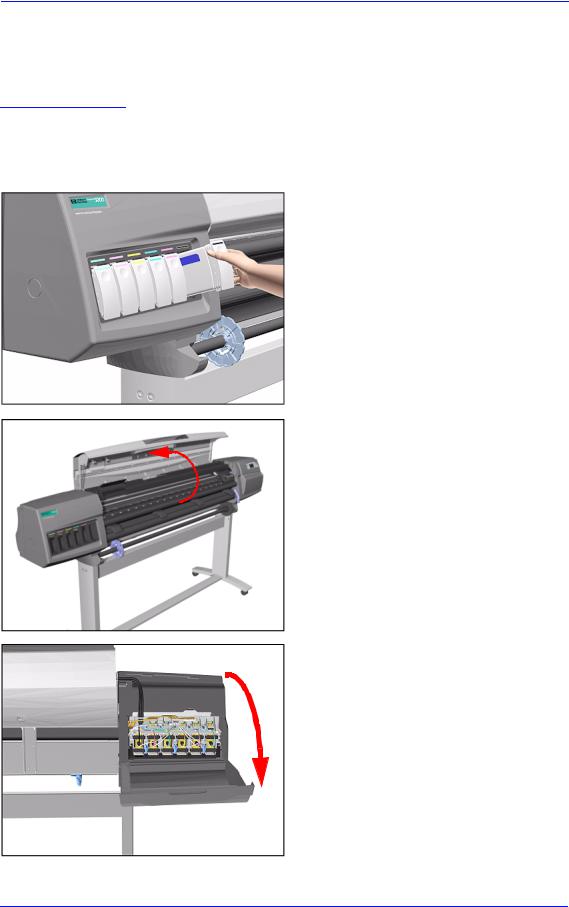
1. Remove ALL the Ink Cartridges from |
|
|
|
the Printer. |
2. Open the Top Cover.
3. Open the door at the back of the Left Hand Cover.
8-6 |
HP DesignJet 5000 and 5500 Series Printers Service Manual |

Removal and Installation
4.Disconnect the Electrical Cable from the rear of the Ink Cartridge Tube Connector.
5. Disconnect the Air Tube.
1
2
6.Twist the 3 latches at the rear of the Ink Cartridge Tube Connector and release the complete Assembly.
HP DesignJet 5000 and 5500 Series Printers Service Manual |
8-7 |

Removal and Installation
7. Remove the Ink Cartridge Tube Connector and place safely on the window.
8. Remove 1 T-15 screw (Type F) from the Left Hand Cover (rear).
9. Close the Left Back door and remove 1 T- 25 screw (Type U) from bottom side (rear) of Left Hand Cover.
|
|
|
|
|
|
|
8-8 |
|
|
|
|
|
HP DesignJet 5000 and 5500 Series Printers Service Manual |

Removal and Installation
10. Remove 3 T-15 screws (Type F) from the Left Hand Cover (front).
11. Remove the Left Hand Cover from the Printer.
Installation of Left Hand Cover
WARNING |
When handling the Tubes make sure you do not damage them by |
|
twisting. |
|
|
|
|
WARNING |
When inserting the Left Hand Cover, be careful not to pinch/ |
|
twist the air tube or the electrical cable. |
|
|
HP DesignJet 5000 and 5500 Series Printers Service Manual |
8-9 |

Removal and Installation
Right Hand Cover
Removal
WARNING
WARNING
NOTE
Switch off the Printer and remove the Power Cord.
To remove the Right Hand Cover you must open the Right Cover door and push in the Printhead Cleaner Carriage.
Refer to the table on Page 8-4 for information on screw types.
1.Remove the Right Rear Cover - Refer to Page 8-16.
2.Remove the Ferrite (if present) and disconnect the Front Panel cable from
the Main PCA (P24) from the left side of the Electronics Module.
P24
3.On the Main PCA, disconnect the Aerosol Fan cable from position P30 and the service station door from position P29.
P29
P30
8-10 |
HP DesignJet 5000 and 5500 Series Printers Service Manual |
Removal and Installation
4.Remove 1 T-15 screw (Type F) and 1 T-25 screw (Type U) (bottom) from the rear of the Right Hand Cover.
5. Open the Top Cover.
6. Raise the Media Lever.
|
|
|
|
HP DesignJet 5000 and 5500 Series Printers Service Manual |
8-11 |
||

Removal and Installation
NOTE Take care not to drop the Cover when removing the screws. Support the Cover throughout the next step.
7. Remove 3 T-15 (Type F) screws from the front of the Right Hand Cover.
8. To release the cables, carefully pull out the Right Hand Cover until the cables can be accessed.
9. Remove the Right Hand Cover.
8-12 |
HP DesignJet 5000 and 5500 Series Printers Service Manual |

Removal and Installation
TIP To check correct functioning of serviced parts on the Printer axis you can do the following:
a Reinsert the top T-15 screw (Type F) at the rear of the Printer.
b Hang the Cover on the screw.
c Connect all cables at the Rear of the Right Cover and turn on the Printer.
Installation of Right Hand Cover
NOTE
Make sure the Front Panel cable and the Aerosol Fan cables are secured inside the Right Hand Cover with cable clamps and retaining pins.
WARNING
Make sure cables pass through slot at rear of chassis on the right hand side otherwise the Cover cannot be properly installed and cables may be damaged.
HP DesignJet 5000 and 5500 Series Printers Service Manual |
8-13 |

Removal and Installation
Front Panel Assembly
Removal
WARNING |
Switch off the Printer and remove the Power Cord. |
|
|
1. |
Remove Right Rear Cover - Refer to |
|
|
Page 8-15. |
|
2. |
Remove Right Hand Cover - Refer to |
|
|
Page 8-10. |
|
3. |
Disconnect the cable from Front |
|
|
Panel. |
4. Unclip Front Panel supports inside the Right Hand Cover and remove.
Lift towards you
8-14 |
HP DesignJet 5000 and 5500 Series Printers Service Manual |

Removal and Installation
Left Rear Cover
Removal
WARNING
NOTE
Switch off the Printer and remove the Power Cord.
Refer to the table on Page 8-4 for information on screw types.
1.Remove one T-15 screw (Type B) from the Left Rear Cover.
NOTE Support the Cover as it is released.
2. Remove the Left Rear Cover.
HP DesignJet 5000 and 5500 Series Printers Service Manual |
8-15 |

Removal and Installation
Right Rear Cover
Removal
WARNING
NOTE
Switch off the Printer and remove the Power Cord.
Refer to the table on Page 8-4 for information on screw types.
1.Remove one T-15 screw (Type B) from the Right Rear Cover.
NOTE Support the Cover as it is released.
2. Remove the Right Rear Cover.
8-16 |
HP DesignJet 5000 and 5500 Series Printers Service Manual |

Removal and Installation
Extension Cover (60" Model only)
Removal
WARNING |
Switch off the Printer and remove the Power Cord. |
|
|
Refer to the table on Page 8-4 for information on screw types. |
|
NOTE |
||
|
1. |
Remove the Left Rear Cover - Refer |
|
||
|
|
to Page 8-15. |
|
2. |
Remove 4 T-15 screws (Type B) from |
|
|
the Extension Cover. |
3. Lift the Cover and remove from the Printer.
HP DesignJet 5000 and 5500 Series Printers Service Manual |
8-17 |

Removal and Installation
Media Lever Assembly
Removal
WARNING |
Switch off the Printer and remove the Power Cord. |
|||
|
Refer to the table on Page 8-4 for information on screw types. |
|||
NOTE |
||||
|
1. |
Only applicable to the DesignJet |
||
|
||||
|
|
|
|
5000 Series - Remove the Deflector |
|
|
|
|
closest to the Right Cover - Refer to |
|
|
|
|
Page 8-119. |
|
2. |
Remove the Right Hand Cover - Refer |
||
|
|
|
|
to Page 8-10. |
|
3. |
Raise the Media Lever. |
||
|
|
|
|
|
|
|
|
|
|
4. Remove 1 T-15 screw (Type D) from the support that attaches the Media Lever to the Sideplate.
8-18 |
HP DesignJet 5000 and 5500 Series Printers Service Manual |

Removal and Installation
5. Remove 1 T-15 screw (Type H) that attaches the Lever Arm to the Lever.
6. Remove the Media Lever.
Installation of the Media Lever Assembly
WARNING |
When installing the Media Lever, you must insert it in the Trim |
|
and Sideplate in the UP position to avoid damaging the Lever |
|
Spring in the Trim. |
|
|
2


1
|
|
|
|
HP DesignJet 5000 and 5500 Series Printers Service Manual |
8-19 |
||

Removal and Installation
Right Hand Trim
Removal
WARNING |
Switch off the Printer and remove the Power Cord. |
|
|
Refer to the table on Page 8-4 for information on screw types. |
|
NOTE |
||
|
1. |
Remove Right Rear Cover - Refer to |
|
||
|
|
Page 8-16. |
|
2. |
Remove Right Hand Cover - Refer to |
|
|
Page 8-10. |
|
3. |
Remove Media Lever Assembly - |
|
|
Refer to Page 8-18. |
|
4. |
Disconnect the Sensors cable from |
|
|
position P27 on the Main PCA. |
P27
5. Remove 1 T-15 screws (Type F) and 1 T-20 (Type L) from the Right Hand Trim.
8-20 |
HP DesignJet 5000 and 5500 Series Printers Service Manual |
Removal and Installation
6. Carefully remove the Right Hand Trim.
Remove carefully
Installation of Right Hand Trim
WARNING |
When installing the Media Lever in the Trim, install with the |
|
Lever in the UP position to avoid damaging the Lever spring in |
|
the Trim. |
|
|
2


1
|
|
|
|
HP DesignJet 5000 and 5500 Series Printers Service Manual |
8-21 |
||

Removal and Installation
Left Hand Trim
Removal
WARNING
NOTE
Switch off the Printer and remove the Power Cord.
Refer to the table on Page 8-4 for information on screw types.
1. Remove 4 T-15 screws (Type F) and 1 T-20 screw (Type L) from the Left Hand Trim.
2. Carefully remove the Left Hand Trim.
Remove carefully
8-22 |
HP DesignJet 5000 and 5500 Series Printers Service Manual |
Removal and Installation
Back Cover
Removal
WARNING
NOTE
Switch off the Printer and remove the Power Cord.
Refer to the table on Page 8-4 for information on screw types.
1.Remove the Top Cover - Refer to Page 8-5.
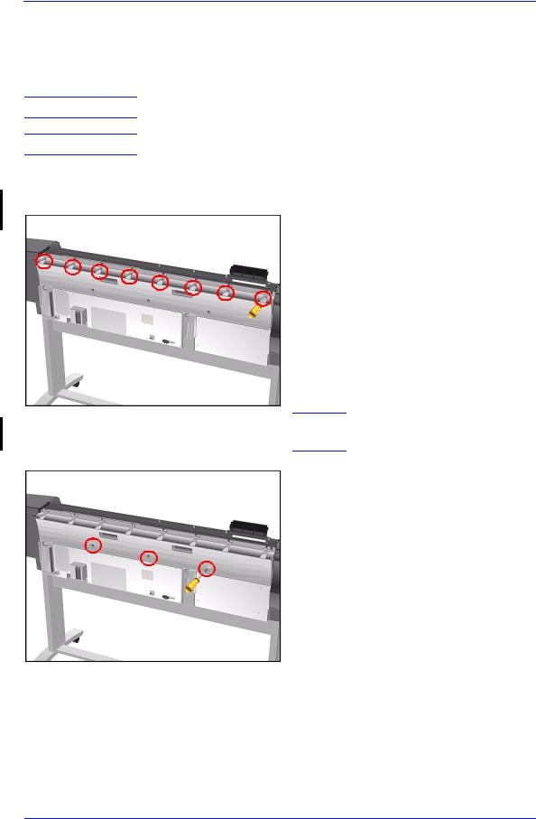
2.Remove the following (Type B) screws from the upper part of the Back Cover:
ν 8 Screws (T-15) for the 60" Model.
ν 6 Screws (T-15) for the 42" Model.
NOTE Support the Back Cover as it is released.
3.Remove 3 T-15 screws (Type N) from the lower part of the Back Cover.
HP DesignJet 5000 and 5500 Series Printers Service Manual |
8-23 |
Removal and Installation
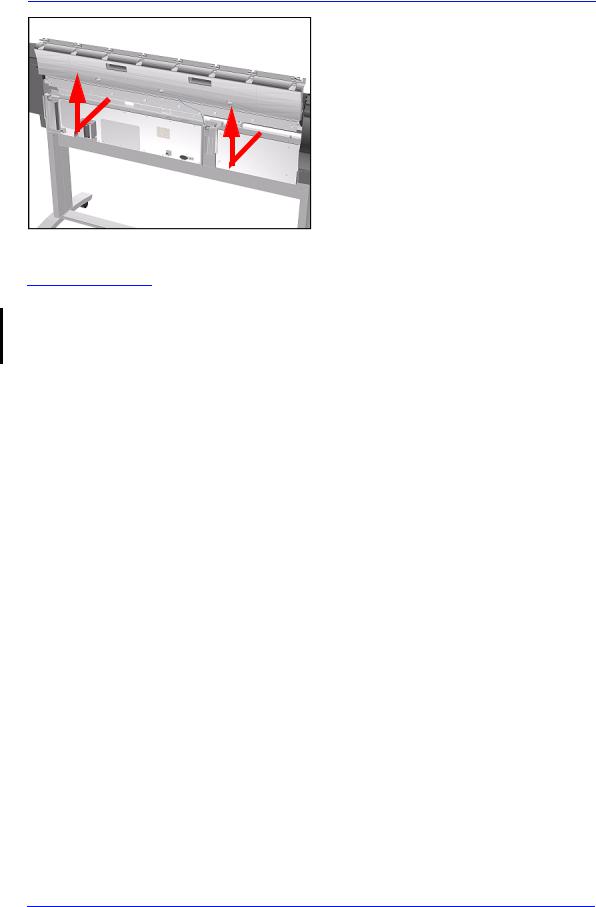
4. Remove the Back Cover.
Installation of the Back Cover
NOTE |
If the Back Cover is replaced, remember to apply a new Printer |
|
Label to the new Back Cover before it is installed. Once the new |
|
label has been applied, copy the product number and serial |
|
number onto it. |
|
|
8-24 |
HP DesignJet 5000 and 5500 Series Printers Service Manual |
Removal and Installation
Ink Tubes System
Removal
WARNING |
Switch off the Printer and remove the Power Cord. |
|
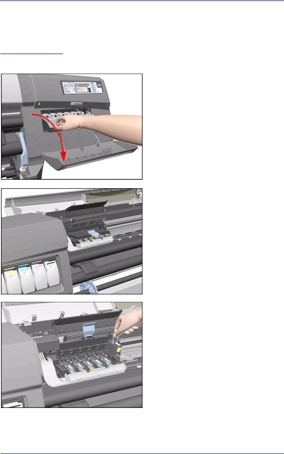
1. Open the Right Cover door and pull |
|
out the Printhead Cleaner Carriage. |
2. Open the Top Cover and pull the Carriage out along the Printer to the position shown.
3. Lift up the Carriage Cover and remove ALL the Printheads and close the Carriage Cover.
HP DesignJet 5000 and 5500 Series Printers Service Manual |
8-25 |

Removal and Installation
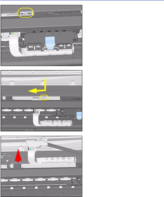
4. Slide the Carriage to the position shown.
5. Push in the 2 retaining clips either side of the Printhead Tube Connector.
6. Pull the Printhead Tube Connector
towards you.
8-26 |
HP DesignJet 5000 and 5500 Series Printers Service Manual |
Removal and Installation
7.Push the button to release the Printhead Tubes in the Carriage.
8.Release the Retaining Clip by pulling it away from the holding brackets.
9.Pull the Printhead Tube Connector up between the two Tube Guides.
|
|
|
|
|
|
|
|
|
|
|
|
|
|
|
|
|
|
|
|
|
|
|
|
|
HP DesignJet 5000 and 5500 Series Printers Service Manual |
8-27 |
|||

Removal and Installation
10. Lift out the blue Retaining Clip.
11. Remove ALL the Ink Cartridges from the Printer.
12. Open the door at the back of the Left Cover.
8-28 |
HP DesignJet 5000 and 5500 Series Printers Service Manual |

Removal and Installation
13.Disconnect the Electrical Cable from the rear of the Ink Cartridge Tube Connector.
14. Disconnect the Air Tube.
1
2
15.Twist the 3 latches at the rear of the Ink Cartridge Tube Connector and release the complete Assembly.
HP DesignJet 5000 and 5500 Series Printers Service Manual |
8-29 |
Removal and Installation
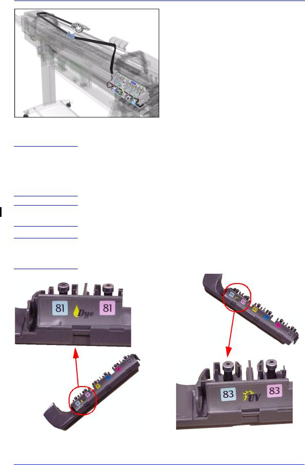
16. The complete assembly can now be removed by sliding the Ink Cartridge Connector out from the rear of the Left Hand Cover.
Installation of Ink Tubes System
WARNING
When installing the Ink Tubes System it is very important that the Tubes are NOT TWISTED. Make sure that the Tubes are correctly routed at the rear of the Left Cover and before powering On the printer, check again that they are NOT TWISTED.
NOTE
NOTE
Do not install NEW Ink Tubes System with Ink Cartridges that indicate Low or Very Low ink levels.
Before installing the new Ink Tubes System, make sure that the Ink Type (Dye or UV) of the Tubes is the same as the ones that you are replacing.
8-30 |
HP DesignJet 5000 and 5500 Series Printers Service Manual |
Loading...