


 Loading...
HP Designjet Z6100 Printer series
Service manual
For HP Internal Use Only Warranty
©Copyright Hewlett-Packard Company 2008
This document contains proprietary information that is protected by copyright. All rights are reserved. No part of this document may be photocopied, reproduced, or translated to another language without the prior written consent of Hewlett-Packard Company.
First Edition, March 2007 Second edtion, May 2008
Customer Assurance
Customer Experience Section
Large Format Printing Division
Hewlett-Packard Espanola, S.A.
Avda. Graells, 501
08190 Sant Cugat del Valles Spain
The information contained in this document is subject to change without notice.
Hewlett-Packard makes no warranty of any kind with regard to this material, including, but not limited to, the implied warranties of merchantability and fitness for a particular purpose.
Hewlett-Packard shall not be liable for errors contained herein or for incidental or consequential damages in connection with the furnishing, performance, or use of this material.
WARNING
The procedures described in this manual are to be performed by HP-qualified service personnel only.
Electrical Shock Hazard
Serious shock hazard leading to death or injury may result if you do not take the following precautions:
-Ensure that the ac power outlet (mains) has a protective earth (ground) terminal.
-Disconnect the Printer from the power source prior to performing any maintenance.
-Prevent water or any other liquids from running onto electrical components or circuits, or through openings in the enclosure.
Electrostatic Discharge
Refer to the beginning of Chapter 4of this manual, for precautions you should take to prevent damage to the Printer circuits from electrostatic discharge.
Safety Symbols
General definitions of safety symbols are given immediately after the table of contents.
WARNING
The Warning symbol calls attention to a procedure, practice, or the like, which, if not correctly performed or adhered to, could result in personal injury. Do not proceed beyond a Warning symbol until the indicated conditions are fully understood and met.
CAUTION
The Caution symbol calls attention to an operating procedure, practice, or the like, which, if not correctly performed or adhered to, could result in damage to or destruction of part or all of the product. Do not proceed beyond a Caution symbol until the indicated conditions are fully understood and met.
HP Designjet Z6100 Printer series
Service manual
Using this Manual
Purpose
This Service Manual contains information necessary to test, calibrate and service:
•HP Designjet Z6100 42-inch Printer (Model Q6651A)
•HP Designjet Z6100 60-inch Printer (Model Q6652A)
For information about using these printers, refer to the corresponding User and Quick Reference Guides.
Readership
The procedures described in this Service Manual are to be performed by HP Certified service personnel only.
Part Numbers
Part Numbers for Printer options, accessories and service parts are located in Chapter 7.
Conventions
A small arrow is used to indicate other parts of the Service Manual where you can find information related to the topic you are consulting.

Table of Contents
1 |
Troubleshooting |
|
|
Troubleshooting the printer.................................................................................................... |
..... 2 |
|
Printer Education and Training..................................................................................... |
2 |
|
Firmware upgrade ..................................................................................................... |
2 |
|
Troubleshooting system error codes............................................................................................. |
2 |
|
Performing a service test on a failed assembly.............................................................................. |
2 |
|
Performing the necessary service calibrations ............................................................................... |
3 |
|
Solving print quality problems .................................................................................................... |
3 |
|
The printer does not power on.................................................................................................... |
3 |
|
Printer hangs during printing and displays ‘processing’ ................................................................. |
3 |
|
The printer continuously rejects printheads ................................................................................... |
4 |
|
A new Maintenenace Cartridge is incorrectly detected as ‘used’ .................................................... |
4 |
|
Cover sensors are not working ................................................................................................... |
4 |
|
The line sensor has problems detecting media .............................................................................. |
5 |
|
Troubleshooting Media Jams/Printhead Crashes........................................................................... |
5 |
|
Troubleshooting shutdowns ........................................................................................................ |
5 |
|
Printhead Maintenance Cartridge Path ......................................................................... |
6 |
|
Paper Path ................................................................................................................ |
6 |
|
Printhead path ........................................................................................................... |
6 |
|
PWM shutdown ......................................................................................................... |
6 |
|
Velocity shutdown ...................................................................................................... |
6 |
|
Energy shutdown ....................................................................................................... |
6 |
|
Vacuum suction much lower at high altitudes................................................................................ |
7 |
|
Banding at variable extreme environmental conditions .................................................................. |
7 |
|
Printhead Crashes/Smears on High Density Prints Using Coated Media .......................................... |
7 |
|
Banding due to ink cartridge replacement while printing ............................................................... |
7 |
|
34" Rice Paper not supported .................................................................................................... |
8 |
|
Worm marks on HP Coated media with light area fills .................................................................. |
8 |
|
Solving Media-Handling Problems .............................................................................................. |
8 |
|
Difficult to load media “Too much skew” ..................................................................................... |
8 |
|
Troublshooting a failure with the Take UP Reel (TUR) ..................................................................... |
9 |
|
Take Up Reel LED status information ............................................................................. |
9 |
|
Checking the Take Up Reel is correctly installed........................................................... |
10 |
|
How the Take UP Reel Works .................................................................................... |
11 |
|
Using the buzzer at power-up for troubleshooting problems........................................... |
11 |
|
Using the Power-up Sequence to Troubleshoot ............................................................. |
12 |
|
Corrective Actions for Power-Up Problems................................................................... |
14 |
|
Troubleshooting OMAS problem .............................................................................................. |
14 |
|
Using the Power Switch LEDs to Troubleshoot ............................................................................. |
15 |
|
Using the PCA LEDs to Troubleshoot.......................................................................................... |
16 |
|
Interconnect PCA ..................................................................................................... |
16 |
|
PrintMech PCA ........................................................................................................ |
17 |
|
Identifying faults from LED status ................................................................................ |
17 |
|
How to Interpret the Service Information Pages ........................................................................... |
19 |
|
Main Characteristics ................................................................................................ |
20 |
|
Current Configuration............................................................................................... |
21 |
|
Current Media, Printhead and Ink Information ............................................................. |
22 |
v
Printer Usage Information.......................................................................................... |
23 |
Media Used Sections................................................................................................ |
24 |
Event Logs............................................................................................................... |
25 |
Calibrations Status ................................................................................................... |
26 |
Connectivity Configuration........................................................................................ |
28 |
When the main window is open and the printer is printing (safety compliance) .............................. |
29 |
General RIP tips and tricks ....................................................................................................... |
29 |
Frequently Asked Questions ...................................................................................... |
30 |
How to troubleshoot the 79:04 System Error .............................................................................. |
31 |
Introduction............................................................................................................. |
31 |
Possible causes........................................................................................................ |
32 |
Troubleshooting based on symptoms .......................................................................... |
38 |
2 System Error Codes
Introduction............................................................................................................................ |
44 |
System Error Codes and Warnings - Explanation........................................................................ |
44 |
Continuable and Non-Continuable Error Codes.......................................................................... |
47 |
3 Ink Supplies
What are Ink Supplies? ........................................................................................................... |
80 |
Ink Cartridges.......................................................................................................... |
80 |
Printheads............................................................................................................... |
81 |
Maintenance Cartridge............................................................................................. |
82 |
General Information About the Ink Supplies ............................................................................... |
82 |
General Precautions When Handling Ink Supplies ...................................................................... |
82 |
Priming the Ink System............................................................................................................. |
83 |
When Should You Replace the Ink Supplies?.............................................................................. |
83 |
Obtaining Ink Cartridge Information ......................................................................................... |
83 |
Obtaining Printhead Information............................................................................................... |
85 |
Ink Cartridge Status Messages................................................................................... |
86 |
Ink Cartridge Status While Printing............................................................................. |
86 |
Ink Cartridge Status While Replacing ......................................................................... |
86 |
Printhead Status Messages While Printing ................................................................... |
87 |
Printhead Status Messages While Replacing................................................................ |
87 |
Maintenance Cartridge Status Messages While Printing ............................................... |
88 |
Maintenance Cartridge Status Messages While Replacing ............................................ |
88 |
Summary of Solving Ink Supplies Problems................................................................................. |
88 |
Problems reseating the printhead ............................................................................... |
88 |
You Cannot Insert the Ink Cartridge Into the Printer....................................................... |
89 |
You Cannot Insert the Printhead Into the Printer............................................................ |
89 |
You Cannot Insert the Maintenance Cartridge Into the Printer ........................................ |
89 |
Troubleshooting Printhead Error Codes...................................................................................... |
90 |
Carriage Interconnect Wiper ................................................................................................... |
91 |
Warranty Information for Ink Supplies ....................................................................................... |
91 |
Ink Cartridge........................................................................................................... |
91 |
Printheads............................................................................................................... |
92 |
4 Service Tests and Utilities
Introduction................................................................................................................... |
|
......... 94 |
Diagnostics - Self Test........................................................................................................ |
...... 94 |
|
Phone Support........................................................................................................................ |
94 |
|
Service Tests (Diagnostics) ....................................................................................................... |
94 |
|
Entering the Service Tests Menu................................................................................................ |
96 |
|
1. |
Scan Axis Test ..................................................................................................... |
97 |
2. |
Paper Drive Test................................................................................................. |
101 |
3. |
Electronics Module Test....................................................................................... |
105 |
4. |
Carriage Assembly Test ...................................................................................... |
112 |
5. |
Sensors Test ...................................................................................................... |
112 |
6. |
Ink Delivery System Test ...................................................................................... |
115 |
7. |
SVS Test ........................................................................................................... |
116 |
8. |
Air Pump System Test ......................................................................................... |
116 |
9. |
Vacuum Fans Test .............................................................................................. |
117 |
vi
10. |
OMAS Module Test.......................................................................................... |
118 |
|
11 EEROM Reset ................................................................................................... |
118 |
||
12. |
Color Sensor Test............................................................................................. |
119 |
|
13. |
Aerosol Test .................................................................................................... |
122 |
|
14. |
Primer Test ...................................................................................................... |
122 |
|
15.1 Service Special Utilities >>> Bag Broken Recovery............................................. |
124 |
||
15.2 Service Special Utilities >>> Error 71:19 Recovery ............................................ |
126 |
||
15.3 Service Special Utilities >>> IO Information ...................................................... |
128 |
||
15.4 Service Special Utilities >>> Unit Information .................................................... |
128 |
||
15.5 Service Special Utilities >>> Check Ink Supplies ................................................ |
129 |
||
Emergency Firmware Upgrade ................................................................................ |
130 |
||
Service Utilities ..................................................................................................................... |
132 |
||
Entering the Service Utilities Menu............................................................................ |
133 |
||
1. |
Turn Drive Roller ................................................................................................ |
134 |
|
2. |
Prime Tubes....................................................................................................... |
135 |
|
3. |
Set SN.............................................................................................................. |
138 |
|
4. |
Reset Life Counters ............................................................................................. |
138 |
|
5. |
Diagnostic Print ................................................................................................. |
140 |
|
6. |
Sleep Mode ...................................................................................................... |
141 |
|
7. |
Replace Cutter ................................................................................................... |
142 |
|
8. |
Set RTC Clock.................................................................................................... |
142 |
|
9. |
Enable/Disable Firewall ..................................................................................... |
143 |
|
10. |
Prime Printhead X............................................................................................. |
144 |
|
11. |
Open/Close SOL............................................................................................. |
145 |
|
12. |
Disk Wipe DoD 5330.22’M ............................................................................. |
145 |
|
13. |
Enable/Disable SCAPA .................................................................................... |
148 |
|
14. |
Spectrophotometer test (Colormeter test).............................................................. |
148 |
|
5 Service Calibrations
Service Calibrations.............................................................................................................. |
152 |
|
Entering the Service Calibrations Menu ................................................................................... |
153 |
|
1. |
Scan Axis Calibration......................................................................................... |
154 |
2. |
Paper Advance Calibration ................................................................................. |
157 |
3. |
Drop Detector Calibration ................................................................................... |
162 |
4. |
Line Sensor Calibration....................................................................................... |
163 |
5. |
Vacuum Calibration ........................................................................................... |
166 |
6. |
OMAS Calibration............................................................................................. |
167 |
7. |
Primer Calibration.............................................................................................. |
173 |
8. |
Platen Blue Line Calibration................................................................................. |
177 |
6 Print Quality
How to Use the Image Quality Service Diagnostic Print ............................................................. |
181 |
What is the Image Quality Service Diagnostic Print? .................................................. |
181 |
Considerations for Printing the Diagnostic Print .......................................................... |
182 |
Printing the Image Quality Service Print .................................................................... |
182 |
Diagnostic Part 1: Printhead Problems ...................................................................... |
183 |
Diagnostic Part 2: Alignment Test............................................................................. |
184 |
Diagnostic Part 3: Printheads & Paper Advance Test................................................... |
185 |
No Printing Defects Found in the Diagnostic Print ....................................................... |
186 |
Visual Alignment Diagnostic Print ............................................................................. |
187 |
Plot for escalation only............................................................................................ |
190 |
Force Drop Detection.............................................................................................. |
192 |
Disable Paper Advance Sensor................................................................................ |
192 |
Fix paper advance issues........................................................................................ |
192 |
Clean the paper advance sensor window ................................................................. |
194 |
The User Advance Calibration................................................................................. |
194 |
Visual Paper Advance Plot ...................................................................................... |
195 |
Interpreting plot results............................................................................................ |
196 |
Image quality issues by symptom ............................................................................................ |
199 |
There is banding in the image ................................................................................. |
199 |
Lines are too thick, too thin, or missing ..................................................................... |
200 |
vii
Lines appear stepped or jagged .............................................................................. |
200 |
Parts of lines or text are missing............................................................................... |
201 |
Lines are blurred (ink bleeds from lines) .................................................................... |
202 |
Lines are slightly warped ........................................................................................ |
202 |
Dark or light horizontal lines across the image (banding)............................................ |
202 |
The image is grainy. .............................................................................................. |
203 |
The image has a metallic hue (bronzing)................................................................... |
204 |
The printed output is not flat .................................................................................... |
204 |
The print smudges when touched ............................................................................. |
205 |
Defects near the top of a print ................................................................................. |
205 |
There are ink marks on the paper ............................................................................ |
205 |
Colors are inaccurate ............................................................................................. |
206 |
Colors between different HP Designjets do not match ................................................. |
207 |
The output is completely blank ................................................................................. |
209 |
The output contains only a partial print ..................................................................... |
209 |
The image is clipped .............................................................................................. |
209 |
The image is in one portion of the printing area......................................................... |
210 |
The image is unexpectedly rotated ........................................................................... |
210 |
The print is a mirror image of the original ................................................................. |
210 |
The print is distorted or unintelligible ........................................................................ |
210 |
One image overlays another on the same print.......................................................... |
210 |
Pen settings seem to have no effect .......................................................................... |
210 |
The image has a wood-grain appearance (aeroworms) .............................................. |
210 |
CAD Lines look misaligned, images are blurred......................................................... |
211 |
Some media might deform when printing high area fill ............................................... |
211 |
Printheads fail repeatedly........................................................................................ |
211 |
Working with other commercially available media ................................................................... |
213 |
7 Parts and Diagrams
Printer Support ..................................................................................................................... |
222 |
Center Covers ...................................................................................................................... |
224 |
Electronics Module................................................................................................................ |
226 |
Right Cover.......................................................................................................................... |
228 |
Left Cover ........................................................................................................................... |
230 |
Right Hand Assemblies.......................................................................................................... |
232 |
Left Hand Assemblies ............................................................................................................ |
234 |
Carriage Assembly ............................................................................................................... |
236 |
Scan-Axis Assemblies ............................................................................................................ |
238 |
Drive Roller and Media-Axis Motor ......................................................................................... |
240 |
Paper Path Assemblies .......................................................................................................... |
242 |
Center Guide and Pinchwheel Assembly.................................................................................. |
244 |
Media Entry Assemblies ........................................................................................................ |
246 |
Take-Up Reel Assembly.......................................................................................................... |
248 |
Miscellaneous Parts............................................................................................................... |
250 |
8 Removal & Installation
Service Part Order ................................................................................................................ |
253 |
Disassembly Order ............................................................................................................... |
255 |
Introduction.......................................................................................................................... |
257 |
Safety Precautions.................................................................................................. |
257 |
Electrostatic Discharge (ESD) Precautions .................................................................. |
257 |
Required Tools....................................................................................................... |
257 |
Screw Types ........................................................................................................................ |
259 |
Window (42-inch) ................................................................................................................ |
260 |
Installation of New Window ................................................................................... |
261 |
Window (60-inch) ................................................................................................................ |
262 |
Right Cover.......................................................................................................................... |
264 |
Right Trim ............................................................................................................................ |
267 |
Left Cover ............................................................................................................................ |
270 |
Left Trim............................................................................................................................... |
272 |
Top Cover (42-inch) .............................................................................................................. |
273 |
viii
Top Cover (60-inch) .............................................................................................................. |
277 |
Rear Door (42-inch) .............................................................................................................. |
281 |
Rear Door (60-inch) .............................................................................................................. |
283 |
Right Connector Cover .......................................................................................................... |
285 |
Left Connector Cover (42-inch) ............................................................................................... |
287 |
Electronics Module Extension (60-inch only) ............................................................................. |
288 |
Window Position Sensor........................................................................................................ |
289 |
Front Panel........................................................................................................................... |
292 |
Primer Assembly ................................................................................................................... |
294 |
Primer Valves ....................................................................................................................... |
296 |
Service Station ..................................................................................................................... |
300 |
Vacuum Fan......................................................................................................................... |
304 |
Aerosol Fan and Filter ........................................................................................................... |
307 |
Drop Detector....................................................................................................................... |
309 |
Ink Supply Tubes and Trailing Cable ....................................................................................... |
312 |
ISS to Cartridge Cables......................................................................................................... |
318 |
Cutter Assembly.................................................................................................................... |
319 |
Ink Supply Station (ISS).......................................................................................................... |
321 |
APS Assembly ...................................................................................................................... |
324 |
Left Spittoon ......................................................................................................................... |
328 |
Encoder Strip and Encoder Sensor .......................................................................................... |
331 |
Carriage PCA ...................................................................................................................... |
334 |
Carriage Flex Cables ............................................................................................................ |
337 |
Carriage Assembly ............................................................................................................... |
339 |
Belt Assembly....................................................................................................................... |
345 |
Scan-Axis Motor ................................................................................................................... |
346 |
Media-Axis Motor................................................................................................................. |
349 |
Optical Media Advance Sensor (OMAS) ................................................................................. |
351 |
Interconnect PCA .................................................................................................................. |
357 |
EIO to PCA Interface Card..................................................................................................... |
360 |
OMAS Controller Card ......................................................................................................... |
362 |
OMAS Cable....................................................................................................................... |
364 |
Sausalito PCI PCA ................................................................................................................ |
369 |
CPU Fan.............................................................................................................................. |
371 |
Memory Module................................................................................................................... |
373 |
Main PCA Formatter ............................................................................................................. |
375 |
Hard Disk Drive (HDD) .......................................................................................................... |
377 |
Power Supply Unit (PSU)........................................................................................................ |
379 |
PrintMech PCA ..................................................................................................................... |
384 |
Formatter Battery .................................................................................................................. |
386 |
Electronics Module................................................................................................................ |
388 |
Line Sensor Assembly ............................................................................................................ |
390 |
Color Sensor Assembly.......................................................................................................... |
392 |
Color Sensor Actuator Assembly............................................................................................. |
395 |
Media Deflector ................................................................................................................... |
397 |
Output Platen ....................................................................................................................... |
398 |
Center Platen ....................................................................................................................... |
400 |
Cartridge Tray...................................................................................................................... |
409 |
Input Roller .......................................................................................................................... |
411 |
Maintenance Cartridge Door ................................................................................................. |
413 |
Maintenance Cartridge Door Sensor ....................................................................................... |
414 |
Media Sensor ...................................................................................................................... |
415 |
Encoder Disc and Sensor....................................................................................................... |
417 |
Media Lever Assembly .......................................................................................................... |
420 |
Media Lever Sensor .............................................................................................................. |
423 |
Pinchwheel Assembly ............................................................................................................ |
425 |
Center Guide ....................................................................................................................... |
430 |
Drive Roller .......................................................................................................................... |
433 |
Right Rollfeed Module Assembly ............................................................................................. |
439 |
ix
Left Rollfeed Module Assembly ............................................................................................... |
440 |
Take-Up Reel Motor .............................................................................................................. |
442 |
Take-Up Reel Left Hand Module.............................................................................................. |
444 |
Take-Up Reel Deflector Supports ............................................................................................. |
445 |
Take-Up Reel Sensors ............................................................................................................ |
447 |
9 Preventive Maintenance
Preventive Maintenance......................................................................................................... |
452 |
Moisture on the Printer............................................................................................ |
452 |
Noisy Carriage Bushing ......................................................................................... |
452 |
Belt Swelling ......................................................................................................... |
452 |
Cleaning the Printer ............................................................................................... |
452 |
General Cleaning .................................................................................................. |
452 |
Cleaning the Drive Roller and Overdrive................................................................... |
452 |
Cleaning the Platen ................................................................................................ |
453 |
Clean the Encoder Strip .......................................................................................... |
454 |
Clean the paper-advance sensor window.................................................................. |
457 |
Applying Oil to the Overdrive ................................................................................. |
458 |
Lubricating the Carriage Assembly........................................................................... |
458 |
Change the maintenance absorber .......................................................................... |
459 |
Scheduled Maintenance ......................................................................................... |
460 |
Level of Printer Usage ............................................................................................. |
460 |
x
1 Troubleshooting
• |
Troubleshooting the printer ..................................................................................... |
2 |
|
• Printer Education and Training.......................................................................... |
2 |
|
• Firmware upgrade .......................................................................................... |
2 |
• Troubleshooting system error codes.......................................................................... |
2 |
|
• Performing a service test on a failed assembly........................................................... |
2 |
|
• Performing the necessary service calibrations ............................................................ |
3 |
|
• Solving print quality problems................................................................................. |
3 |
|
• The printer does not power on ................................................................................ |
3 |
|
• Printer hangs during printing and displays ‘processing’ .............................................. |
3 |
|
• The printer continuously rejects printheads ................................................................ |
4 |
|
• A new Maintenenace Cartridge is incorrectly detected as ‘used’.................................. |
4 |
|
• Cover sensors are not working ................................................................................ |
4 |
|
• The line sensor has problems detecting media........................................................... |
5 |
|
• Troubleshooting Media Jams/Printhead Crashes ....................................................... |
5 |
|
• |
Troubleshooting shutdowns ..................................................................................... |
5 |
• Vacuum suction much lower at high altitudes............................................................. |
7 |
|
• Banding at variable extreme environmental conditions ............................................... |
7 |
|
• Printhead Crashes/Smears on High Density Prints Using Coated Media ....................... |
7 |
|
• Banding due to ink cartridge replacement while printing ............................................ |
7 |
|
• 34" Rice Paper not supported ................................................................................. |
8 |
|
• Worm marks on HP Coated media with light area fills ............................................... |
8 |
|
• |
Solving Media-Handling Problems........................................................................... |
8 |
• Difficult to load media “Too much skew”................................................................... |
8 |
|
• Troublshooting a failure with the Take UP Reel (TUR) .................................................. |
9 |
|
• Using the buzzer at power-up for troubleshooting problems ....................................... |
11 |
|
• Using the Power-up Sequence to Troubleshoot .......................................................... |
12 |
|
• |
Troubleshooting OMAS problem ............................................................................ |
14 |
• Using the Power Switch LEDs to Troubleshoot............................................................ |
15 |
|
• Using the PCA LEDs to Troubleshoot........................................................................ |
16 |
|
• How to Interpret the Service Information Pages ......................................................... |
19 |
|
• When the main window is open and the printer is printing (safety compliance) ........... |
29 |
|
• General RIP tips and tricks.................................................................................... |
29 |
|
• How to troubleshoot the 79:04 System Error ............................................................ |
31 |
|
Troubleshooting
1

Troubleshooting
Troubleshooting the printer
Refer to Section 6 for troubleshooting Image Qulaity issues.
Printer Education and Training
Before any attempt is made to troubleshoot the printer, it is critical that you have the relevant training on the HP Designjet Z6100 Printer series. If you are not trained on this printer, please contact HP Education or HP Training to enquire about becoming ‘HP Service Qualified’ for this printer.
Firmware upgrade
The first step to take when trying to clear an errror with the printer is to check that the firmware installed in the printer is the latest available. Firmware updates often include fixes for some of the problems that are found in the following pages, simply updating the firmware can often resolve the problem. New firmware can be downloaded from the following url: http:www.hp.com/go/designjet/downloads
If the error with the printer does not allow you to upgrade the firmware using the normal process, try upgrading the firmware using the emergency .plt file procedure page 130
Troubleshooting system error codes
Chapter 2, System Error Codes contains a list of system error codes and their respective descriptions and recommended corrective actions. Only try one recommended action at a time and check if the error code has disappeared.
If you have an error code which is not documented in this Service Manual or you have an error which you cannot resolve, then report the error to the HP Response Center or the nearest HP Support Office. When reporting the error, have the following information ready:
•Model and Serial Number of the printer.
•Which firmware revision the printer is using (See Note below). Check firmware in Utilities / Statistics / Code rev.
•The complete error number.
NOTE: When reporting the System Error Code, make sure that you supply the full Error Code and the firmware version. Without this information, HP Support Personnel cannot help you.
•The Service Configuration Print.
•The Current configuration sheet.
•Which software application the customer is using (name, version, etc.).
Performing a service test on a failed assembly
If possible, always perform a Service Test on the component/assembly that you are about to replace, just to make sure that is the component/assembly that has failed.
NOTE: If the test on that component/assembly passes, you should NOT replace it.
For information on the Service Tests and how to use them see Chapter 4, Service Tests and Utilities.
2 Chapter 1 Troubleshooting

Performing the necessary service calibrations
Is the printer calibrated correctly after replacing a component? For information on the Service Calibrations and how to use them see Chapter 5, Service Calibrations.
NOTE: Remember that certain Calibrations are required even if an Assembly has been disassembled to gain access to another Assembly or Component.
Solving print quality problems
Whenever a Print Quality problem appears, it is advisable to print the Diagnostic Print to help diagnose the problem. The Diagnostic Print will help you differentiate between possible printhead errors and other problems such as incorrect front-panel selection, driver or RIP configuration or mechanical problems. For information on solving Print Quality problems see Chapter 6, Print Quality.
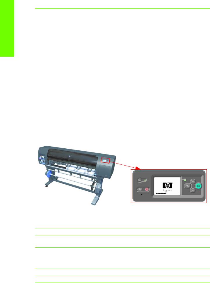
The printer does not power on
To resolve printer power up problems, do the following:
1.Check that the power cord is connected correctly to the Printer and to the Power Socket.
2.Check that the Power Switch on the BACK of the Printer is in the ON position.
3.Check to see if any of the LEDs on the Power Switch are On. If any of the LEDs are On, then refer to See page 15 for more information.
4.Check that the Front-Panel Cable is correctly connected to the Electronics Module. Also make sure that the Front-Panel cable is not damaged.
5.Replace the CPU Fan See page 371
6.Replace the Power Supply Unit See page 379.
Printer hangs during printing and displays ‘processing’
It has been seen under certain circumstances that the printer hangs whilst printing, this may happen immediately after printing, or only a partial print. In some cases when this occurs if the machine is rebooted a system error 79:04 is displayed, although rebooting again appears to clear this error. After this point, although the printer displays that it is in the “Ready” state, attempting to print anymore plots will once again hang the printer, including internal demo plots.
Reason
The reason for this error is that a large spooled file (11Gb for example) has been sent to the printer and has been placed in the disk partition which is related to the print queue. The file completely fills up all the disk space, because of this it will never successfully print, and so the file remains in the disk partition.
Even after restarting the printer the file remains, subsequent print requests also fail as there is not sufficient space available in the partition to process anything else.
Solution
Perform the following few steps to clear the error.
Troubleshooting
Performing the necessary service calibrations |
3 |

Troubleshooting
1.Check that the firmware is the latest available (at least 7.0.03)
2.Turn Off and ON the printer.
3.Set Queue to OFF.
4.Set ‘When Start Printing’ to ‘Immediately’.
Please guide the customer through the front panel of the printer to set up the “Queue” to “OFF” and “When Start Printing” to “Immediately”.
Wipe disk solution
If the above procedure does not clear the error, use the wipe the hard disk procedure (Unsecure mode)See page 145. This will delete all previous jobs, ICC profile, media profiles that were present on the hard disk. This procedure has an advantage for the customer in that it solves the issue without the need to wait for an onsite engineer to come to their premises and remove and replace the HDD (which would also have the same affect of deleting all the previous jobs, ICC profiles and media profiles). The whole procedure should not take more than 30-35 minutes.
Important step is that you need to select the Unsecure mode
The printer continuously rejects printheads
To resolve printhead rejection problems, do the following:
1.Clean the flex contacts on the Printhead and in the Carriage Assembly using the Carriage Interconnect Wiper (Refer to Chapter 3) and try again.
2.If ALL the Printheads are rejected (the status message on the Front Panel does NOT show “OK” for ALL the Printheads) then perform the Electronic Systems Test See page 105.
A new Maintenenace Cartridge is incorrectly detected as ‘used’
This can occur if the printer has detected the previous Maintenenace Cartridge was nearly full, and when a new Maintenenace Cartridge is installed the Front Panel displays an error that the cartridge is ‘used’. To resolve the problem, do the following:
1.Ensure the firmware installed in the printer is the latest available.
2.Once the latest firmware is installed repeat the Maintenance installation procedure with the same cartridge.
3.Manuall reset the counter of the Maintenance Cartridge See page 138
Cover sensors are not working
To resolve cover sensor problems, do the following:
1.Perform the Sensors Test See page 112.
2.Check if the cable for the faulty sensor is not damaged and is connected correctly.
3.Replace the faulty Sensor.
4 Chapter 1 Troubleshooting

The line sensor has problems detecting media
To resolve line sensor media detection problems, do the following:
1.Check the type of media that is being used since the Line sensor may have problems detecting transparent media or some types of Non-HP media. Try loading white HP media in to the Printer and check if the Line sensor detects it.
2.Excessive ink deposits on the Platen surface can fool the sensor by reflecting the light. Clean the Center Platen.
3.Clean the Encoder Strip See page 454.
4.The Line Sensor is not calibrated correctly. Perform the Line Sensor Calibration See page 163.
5.The Line Sensor is damaged or faulty. Replace the Line Sensor See page 390.
Troubleshooting Media Jams/Printhead Crashes
NOTE: If you are using HP Coated Media when the problem occurred, please also refer to Page 1-6.
The failure modes “media jam” and “head crash” are grouped together because in many cases a media jam causes the media to lift up into the Carriage path and cause a Printhead crash, thus causing many media jam failures to be reported as head crashes.
1.Did the media jam occur when loading media?
NOTE: When clearing a media jam, sometimes media is stuck in the paper path. To clear this, you must lift the Media Lever and insert thicker media into the paper path to push out the media that is still stuck there.
•If the client has had media jams, it is common for pieces of media to get stuck in the media path. Clear the media path.
2.Is the customer using non-HP media?
•The use of non-HP media can easily be the cause of media jams and head crashes (especially head crashes because HP media is specially formulated to avoid cockle, one of the primary causes of head crashes). If the media is not HP approved, advise the customer to use HP media and check to see if the problem is now solved.
3.Check that the Vacuum Fan works correctly.
Troubleshooting shutdowns
If a shutdown occurs, you will get the message “Switch Power Off” followed by one of these messages:
•Check Maintenance Cartridge Path.
•Check Paper Path.
Troubleshooting
The line sensor has problems detecting media |
5 |

Troubleshooting
•Check Printhead Path.
NOTE: A shutdown in each path will require different steps to resolve the problem as explained below. In each case, make sure that you power OFF the printer before attempting any procedures to resolve the problem.
Printhead Maintenance Cartridge Path
Open the right door of the printer and check for any visible obstacles restricting the movement of the Service Station. Manually move the Service Station, checking for smooth and free movement.
Paper Path
To resolve paper path problems, do the following:
1.Open the Window and check for any visible obstacles restricting the movement of the Drive Roller. Make sure that the mylar is not damaged. If there is a wrinkled mass of media inside the paper path, lift the Pinch wheels (using the Media Load Handles) and clear the obstruction.
2.If this shutdown happens at the end of a Roll of Media, it could be because the media is stuck firmly to the Roll. Lift the Pinch wheels (using the Media Load Handles) and pull the media clear.
3.Replace media spindle if broken.
4.Replace the Media-Axis Motor See page 349.
Printhead path
When a shutdown occurs in the Printhead path, you will get the message “Switch Power Off / Check Printhead Path (*). The (*) will be a number, which will give an indication on where the failure occurred:
PWM shutdown
To resolve a PWM shutdown, do the following:
1.Clean Slider Rods and Apply Oil along the complete axis of the Slider Rods. After applying the Oil, perform the Scan-Axis Test See page 97 and check that the values are within the given limits.
2.Clean the Encoder Strip See page 454.
3.Replace the Scan-Axis Motor See page 346.
Velocity shutdown
To resolve a velocity shutdown, do the following:
1.Open the Window and check for any visible obstacles restricting the movement of the Carriage Assembly. Try and move the Carriage Assembly manually, checking for smooth and free movement.
2.Check that the Encoder Strip is clean. If necessary, clean Encoder Strip using a damp cloth.
Energy shutdown
To resolve an energy shutdown, do the following:
1.Clean Slider Rods and Apply Oil along the complete axis of the Slide Rods. After applying the Oil, perform the Scan-Axis Test See page 97 and check that the values are within the given limits.
2.Clean the Encoder Strip See page 454.
6 Chapter 1 Troubleshooting

3.Replace the Scan-Axis Motor See page 346.
Vacuum suction much lower at high altitudes
At altitudes above 3,000 meters, the vacuum force holding down the media will be lower, therefore the media will not be held in place properly causing:
•Ink Smearing on the Media.
•Printhead crashes against the Media.
•Roll Media loading problems (low probability). PRINTER LIMITATION - NO SOLUTION AVAILABLE.
Banding at variable extreme environmental conditions
NOTE: This problem is only applicable if the OMAS is disabled.
Since the Accuracy Calibration has been done at normal environmental conditions, printing in extreme environmental conditions will cause banding because the advance of the Drive Roller does not correspond to the same conditions that the calibration was done in. To solve the problem, try the following:
Perform the Accuracy Calibration in the new environmental conditions (Refer to the User’s Guide).
Printhead Crashes/Smears on High Density Prints Using Coated Media
High density prints can cause cockle mainly on HP Coated Media. This causes two main problems:
1.Cockling in the borders - Because the printer places too much ink on the Coated Media, the borders of the print become raised, causing the Printhead to crash against the media. To solve the problem, try the following:
•Change the paper margins to 15mm, either in the Front Panel or in the Driver. If the customer is printing PostScript images, send them a PPD file containing the extended margins of 15mm.
2.Cockling within the print - If the Printer places too much ink within the print, the media starts to ripple, causing the Printhead to smear against the media. To solve the problem, try the following:
•Check in the Front Panel if Ink Limiting is ON or OFF. If Ink Limiting is OFF, turn it ON.
•Never use HP Coated Media for High Density prints. As a substitute use HP Heavy Coated Media.
Banding due to ink cartridge replacement while printing
A user has removed the Ink Cartridge while the printer was printing, which has caused the printer to stop. If the user does not replace the Ink Cartridge immediately, when the printer starts to print again, a band will appear in the position where the printing restarted. This is because the wet ink interacts with the dried ink on the media causing the band to appear. To solve the problem, try the following:
Troubleshooting
Vacuum suction much lower at high altitudes |
7 |

Troubleshooting
•Do NOT remove the Ink Cartridge while the Printer is Printing. Only replace/remove Ink Cartridges in between Prints.
•If the Ink Cartridge was replaced due to the “Empty” status on the Front Panel, then advise the customer to replace the Ink Cartridge when the “Very Low” status is showing on the Front Panel.
•Reprint the file (without remove the Ink Cartridge).
34" Rice Paper not supported
Roll length is 34" (Non-standard) and the pinch wheels can't control edge of media causing ink smears and Printhead crashes in middle of prints with or without area fills.
PRINTER LIMITATION - NO SOLUTION AVAILABLE.
Worm marks on HP Coated media with light area fills
Light bands (S-shaped) in Paper axis direction where light area fills are printed, causing unacceptable Image Quality defect.
•Print the Service Configuration Print and check if the level of Humidity is very low (below 30%). Increasing humidity may help in reducing the severity of the problem.
NOTE: The media is causing the problem and NOT the Printer. Do not attempt to try and replace Printer parts to solve this problem.
Solving Media-Handling Problems
The Front Panel Keeps Indicating that Media Is Misaligned or Incorrectly Positioned.
•The roll may be loaded the wrong way. The paper should load over the roll toward you.
•Check that the paper is correctly loaded onto the spindle.
•The paper may be loaded at an angle. The right-hand edge must be aligned with the blue line on the Print Platen.
NOTE: Ensure that the paper is wrapped tightly on the roll. This is a very important step to remember because if this is not done, the media may be loaded at an angle, causing the media to be rejected.
Difficult to load media “Too much skew”
If you encounter a high failure rate when loading media and the Front Panel reports “Too Much Skew” it is likely that:
•The encoder strip must be cleaned (this can be carried out by the customer using the User Maintenance Kit).
•The Line Sensor must be cleaned.
•The Blue Line calibration must be performed (see “8. Platen Blue Line Calibration” on page 177).
8 Chapter 1 Troubleshooting

Troublshooting a failure with the Take UP Reel (TUR)
Use this section to troubleshoot failures with the TakeUP Reel.
Take Up Reel LED status information
LED |
Issue |
Print job |
Possible cause |
Print job |
status |
|
interupted |
|
interrupted? |
|
|
|
|
|
Blinking |
Take Up Reel |
Yes |
Sensor beam blocked for |
Ensure the Take Up Reel sensors |
quickly |
not winding |
|
more than 3 seconds |
are not blocked by a strip of |
|
|
|
|
paper, the collection bin or other |
|
|
|
|
objects. |
|
|
|
|
Also ensure the Take Up Reel |
|
|
|
|
power switch is in the On posi- |
|
|
|
|
tion. |
|
|
|
|
|
Blinking |
Take Up Reel |
No |
The sensor cables are |
Ensure the sensor cables are cor- |
slowly |
not winding |
|
loose or unplugged |
rectly connected. |
|
|
|
|
|
Solid red |
Take Up Reel |
No |
There is too much resis- |
ENSURE THAT THE TUR Spindle |
|
not winding |
|
tance on the Take Up Reel |
Lever is CLOSED! Ensure the |
|
|
|
motor |
paper is not winding too tightly. |
|
|
|
|
A loop-shaping core should be |
|
|
|
|
inserted and hanging down. |
|
|
|
|
|
Solid green |
Take Up Reel |
No |
The Take Up Reel power |
Ensure the Take Up Reel power |
|
not winding |
|
switch is in the Off posi- |
switch is in the On position. |
|
|
|
tion |
|
Solid green Take Up Reel |
No |
The Take Up Reel wind |
winding in the |
|
direction switch is in the |
wrong direc- |
|
wrong winding position. |
tion, and not |
|
after 3 seconds, the |
stoppinjg the |
|
printer will recognize the |
job. |
|
problem and interupt the |
|
|
print job. In this case, see |
|
|
the first error listed in this |
|
|
table. |
Flip the Take Up Reel wind-direc- tion switch to the correct position.
NOTE: If the LED is flashing but there is no message on the front panel, restart the printer.
Troubleshooting
Troublshooting a failure with the Take UP Reel (TUR) |
9 |
Troubleshooting
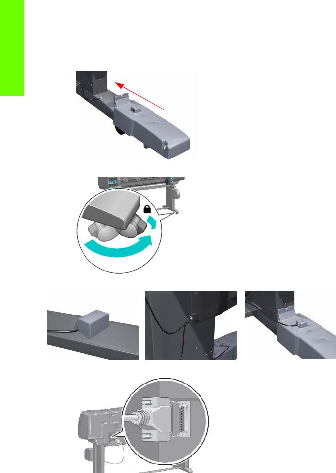
Checking the Take Up Reel is correctly installed
Many system error codes are displayed as a result of the Take UP Reel not being installed correctly or because parts have moved or become dislodged from their correct positions. This troubleshooting procedure checks the machnical installation of the Take Up Reel.
1.Check that the Take UP Reel sensor unit is correctly installed on the right foot.
2.To correctly install the foot, the wheel has to be positioned as shown.
3.Check the cables linking the sensors to the Take Up Reel Motor Assembly are correctly connected.
4.Check that the Take UP Reel motor assembly is correctly connected to the rear of the printer.
10 Chapter 1 Troubleshooting
How the Take UP Reel Works
There are two different setups:
1.The Take Up Reel has been installed via the front panel from the media menu – how to check it: If the words 'Take Up Reel installed' is blanked out, this means that the Take Up Reel is not installed in the front panel.
2.The Take UP Reel has not been install via the front panel – how to check it: When selecting the media menu, there is no line ‘Take Up Reel installed’. This does not mean that the Take Up Reel will not work, it just means that if there is a paper jam detected by the Take Up Reel, there will be no warning system error displayed on the front panel. The printer will not stop.
How to install the Take Up Reel:
From the Media menu -> Take Up Reel -> Enable Take Up Reel. The main differences between the two modes (Take Up Reel installed or not installed on the front panel), what will happen if the Take Up Reel is installed:
•In case of Take Up Reel Paper jam system error, a warning is reported on the front panel, and the printer is no more printing (pause)
•The cutter is disabled between jobs
•When unloading the media, the front panel will ask you to manually cut the media.
How it works?
When the bottom of the 'loop shaper' is lower enough and it cuts the signal between the 2 sensors, the Take Up Reel starts to move the motor until the signal between the 2 sensors is passing through again.
If after the few seconds of turning the Take Up Reel, the signal between two sensors is still cut, the Take Up Reel reports a 'Take Up Reel paper jam' error:
•In all case, the LED of the Take Up Reel is blinking quickly
•and if the Take Up Reel is enabled on the front panel, a 'Take Up Reel' paper jam will be displayed.
Using the buzzer at power-up for troubleshooting problems
When the Printer is powered up, it doesn’t make a “Beeping Sound” until it is completely powered-up and ready to use. If there is a beep during the power-up sequence, this may signify that there is a problem within the Electronics Module. The following table will help you to use the “Beeping Sound” to diagnose certain problem:
Number Problem Description |
Corrective Action |
of |
|
Beeps |
|
1 |
Processor absent |
• |
Replace the Main PCA See page 375. |
|
|
|
|
|
|
2 |
Faulty Main PCA or PSU |
• Replace the Main PCA See page 375. |
|
|
• |
Replace the PSU See page 379. |
|
||
|
|
|
||
|
|
|
|
|
|
|
• Check that the Memory Module is installed cor- |
|
|
|
|
|
rectly. |
|
|
|
• Try installing the Memory Module in the other Mem- |
||
|
|
|
ory slot and check if the problem reappears. |
|
3 |
Faulty Memory Module |
• |
If the problem reappears, replace the Memory Mod- |
|
|
|
|
ule See page 373. |
|
|
|
• If the problem does NOT reappear, then the original |
||
|
|
|
slot could be faulty. In this case, replace the Main |
|
|
|
|
PCA See page 375. |
|
|
|
|
||
|
Troublshooting a failure with the Take UP Reel (TUR) |
11 |
||
Troubleshooting
Troubleshooting
Number Problem Description |
Corrective Action |
of |
|
Beeps |
|
4 |
Faulty Video Card (not |
• |
Replace the Main PCA See page 375. |
used) |
|
|
|
|
|
|
|
|
|
|
|
5 |
Faulty PCI Card |
• |
Replace the Main PCA See page 375 |
|
|
|
|
6 |
BIOS Damaged |
• |
Replace the Main PCA See page 375 |
|
|
|
|
7 |
Motherboard damaged |
• |
Replace the Main PCA See page 375 |
|
|
|
|
|
|
• Remove the Main PCA Cover and (with the Printer |
|
|
|
|
switch On) check that the HDD is spinning (you |
|
|
|
should feel it spinning when you touch it or at least |
|
|
|
hear it spinning). If the HDD is not spinning, then it |
8 |
Hard Disk Drive |
|
could be damaged. In this case, replace the HDD |
damaged or missing |
|
See page 377. |
|
|
|
||
|
|
• Make sure that ALL cables connected to the HDD |
|
|
|
|
are not damaged and are connected correctly. |
|
|
• |
Replace the HDD See page 377 |
|
|
• Replace the Main PCA See page 375 |
|
|
|
|
|
Using the Power-up Sequence to Troubleshoot
When the Printer is powered up, it performs the Boot-UP sequence which initializes the major components of the Printer. If for some reason the Boot-Up sequence fails because a components has failed to initialize, the following explanations will help you to locate the failing component.
Step |
Initialization Process |
|
|
BULNEX KERNEL BOOT
30 rc.sysinit rerun through initlog.
29• Environmental variables PATH, NETWORKING, HOSTNAME set.
•Source /etc/init.d functions.
•Fix console loglevel.
28• Mount /proc.
•Dismount the initrd, if necessary.
•Configure kernel parameters.
27 Set the system clock.
26 Load keymap.
12 Chapter 1 Troubleshooting

Step |
Initialization Process |
|
|
25 Load system font.
24 Start up swapping.
23• Set the hostname.
•Initialize USB controller and HID devices
•Set variables for options to be later used for filesystem check
22• Turn Off DMA on CD-ROMs
• Turn On Hard Disk optimization
21 Perform file system check on root volume.
20 Update quotas if fsck was run on root
19Setup pnp
•Remount the root filesystem read-write.
•LVM initialization.
•Clear mtab.
18• Enter root, /proc and (potentially /proc/bus/usb and devfs into mtab.
•Remove /lib/modules/preferred and /lib/modules/default.
•Tweak isapnp settings if needed.
•Load sound modules if the need persistent DMA buffers.
•Load modules from /etc/rc.modules.
17• File system check.
• Add raid devices.
16• Setup Logical Volume Management.
• Check filesystems on all volumes found on /etc/fstab.
15 Mount local filesystems.
14 Check remaining quotas other than root.
13 Enable local filesystem quotas.
12• Configure machine if necessary (if the respective configure files exist).
•Reread in network configuration data.
•Clean out /etc, (w/u)tmpx files, /var.
•Reset pam_console permissions.
•Cleanup utmp/wtmp.
11• Delete X locks.
•Delete VNC and X locks.
•Delete Postgres sockets.
•Turn On swap in case we swap to files.
•Initialize the Serial Ports.
•If a SCSI tape has been detected, load the st module unconditionally.
10• Load usb storage to match most other things.
•If ide-scsi is required, load it.
•Generate a header that defines the boot kernel.
•Dump the syslog ring in /var/log/dmesg.
9• Keep kernel symbols in /var/log/ksyms.
• Create the crash indicator flag to warn on crashes, offer fsck with timeout.
8 Export this variable BOOT_PART and INSTALL_PART.
PRINT APPLICATION STARTING POINT
7 IO kernel mode initialization (basically).
6 Printer Application Infrastructure startup.
Troubleshooting
Troublshooting a failure with the Take UP Reel (TUR) |
13 |
Troubleshooting
Step |
Initialization Process |
|
|
5 Printer IO startup.
4Front Panel application startup (but wait for engine launching, i.e. Front Panel is not cleared yet).
3 Engine startup, start EE and Mechanical initialization.
2HPGL/PS parsers startup. All subsystems launched.
1Wait for Front Panel application to clear the Front Panel and start signaling the initialization sequence.
Corrective Actions for Power-Up Problems
To resolve power-up problems, use the following corrective actions:
1.If the Printer's Power-Up process stops when the front panel is displaying the number 17, this indicates that there is a problem with the file system on the Printer's Hard Disk Drive, so the Printer is checking the whole file system and making any necessary corrections. This problem can arise when there has been a power cut while the Printer was switched On, or if there is a physical problem with the Hard Disk Drive.
Checking the whole file system normally takes about half an hour (but could take much longer). There is nothing that can be done to speed up the file checking process. If you turn Off the Printer during the checking process, the file system check will restart whenever you turn it On again.
If you experience this problem repeatedly when there has been no power cut, then this could mean that the Hard Disk Drive is faulty. In this case, replace the Hard Disk Drive See page 377.
2.If the printer's start-up process stops when the front panel is displaying any number between 1 to 30, then try the following:
•Switch the Power OFF from the back of the Printer and disconnect the Power cord. Reconnect the power cord and power On the Printer.
•If the Printer continues to stop during the power-up process, replace the Hard Disk Drive See page 377.
Troubleshooting OMAS problem
A problem with the OMAS board may cause the printer to display a 50.2:10 service error, this can be fixed by checking the following connections.
1.Check the CAN Cable is correctly connected.
14 Chapter 1 Troubleshooting

2.Check the other end of the CAN cable is also correctly connected
3.Check the LEDs under the OMAS board.
This LED only comes on for the first 20 seconds after the printer is turned On. When the firmware has succesfully loaded into the memory the LED will switch OFF.
These LEDs come On and stay lit. From right to left:
1st LED=24 volts
2nd LED=5 volts
3rd LED=3.3 volts
Troubleshooting
Using the Power Switch LEDs to Troubleshoot
In certain circumstances, the LEDs located on top of the power switch (located at the rear of the Printer) can help to troubleshoot the Printer. The LEDs can either be ON or Off and using different combinations can indicate different problems:
Amber is on the Left
Blue is in the center
Green is on the Right
Make sure you look directly at the LEDs and not at an angle.
Using the Power Switch LEDs to Troubleshoot |
15 |
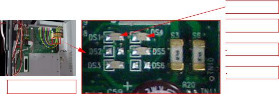
Troubleshooting |
1. |
When only the Amber LED is On: |
|
|||
|
|
• The Printer has been switched Off from the Front Panel (after having pressed the On/Off but- |
||||
|
|
|
||||
|
|
|
ton). |
|
|
|
|
|
|
• The Power Supply Unit only delivers a 5 V “Standby”; power that is needed to restart the Printer |
|||
|
|
|
after the Front Panel On/Off button is pressed (the Formatter/Main PCA will initiate the Printer |
|||
|
|
|
to start). |
|
|
|
|
2. |
When the Blue LED is On: Deliver standard “ATX” power for the Electronics Module PCAs (+12V, |
||||
|
|
|
+5V, -5V, -12V, etc...). All the functions of the Electronics Module are fully operational (EWS, etc...). |
|||
|
3. |
When the Green LED is On: Deliver “analog” 24V and 42V to enable printing. |
||||
|
||||||
|
|
The Printer monitors and reports different signals: PSU fan issues, 24V and 42V delivery failures (specific |
||||
|
|
System Error reported pointing to PSU failure). |
|
|||
|
|
|
|
|
|
|
|
|
|
PSU Blue |
PSU |
|
|
|
|
|
Green |
Left LED (on Front |
|
|
|
|
|
LED |
Printer Status |
||
|
|
|
LED |
Panel) Status |
||
|
|
|
Status |
|
||
|
|
|
Status |
|
|
|
|
|
|
|
|
|
|
|
|
|
|
|
|
|
|
|
|
ON |
OFF |
Red (Front Panel Black) |
Standby (with Embedded Web Server up and |
|
|
|
running) |
|||
|
|
|
|
|
|
|
|
|
|
|
|
|
|
|
|
|
ON |
OFF |
Green (flashing) |
Initializing |
|
|
|
|
|
|
|
|
|
|
ON |
ON |
Green |
Ready (but not printing) |
|
|
|
|
|
|
|
|
|
|
ON |
ON |
Green |
Printing or preparing to print |
|
|
|
|
|
|
|
|
|
|
OFF |
ON |
Any |
Not possible |
|
|
|
|
|
|
|
|
|
|
ON |
ON |
Red (Front Panel Black) |
Not possible |
|
|
|
|
|
|
|
Using the PCA LEDs to Troubleshoot
In certain circumstances, the LEDs located on the Interconnect PCA and PrintMech PCA can help to troubleshoot the Printer. The LEDs can either be ON or Off and using different combinations can indicate different problems.
Interconnect PCA
The following illustration shows the locations of the LEDs on the Interconnect PCA
 DS1: 24V
 DS4: VPOWER2
 DS5: 5V

 DS3: 5Vsb
Interconnect PCA
5V - Comes from the PSU after the fuse on Interconnect PCA. Used to power On Front Panel and some Interconnect Electronics. Should be ON at the same time as Blue Power Switch LED.
5Vsb - Comes from the PSU after the fuse on Interconnect PCA. Used to power On the Printer from the Front Panel. Should be ON at the same time as Blue or Amber Power Switch LED.
16 Chapter 1 Troubleshooting
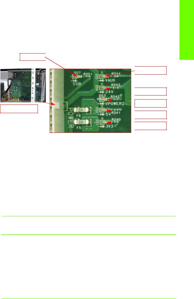
24V - Comes from the PSU after a fuse on the PrintMech PCA.
VPOWER2 - Comes from the PSU (42V) after a fuse on the Interconnect PCA. Used to power the Carriage PCA. Should be ON at the same time as Green Power Switch LED.
PrintMech PCA
The following illustration shows the locations of the LEDs on the PrintMech PCA.
DS7: 5Vsb 
 DS5: VAUX=12V
 DS4: 24V
 DS3: VPOWER2
PrintMech PCA
 DS2: 5V
  DS1: 3V3
5Vsb - Comes from the PSU after the fuse on PrintMech PCA.
3V3 - Comes from the Power Supply Unit.
5V - Comes from the Power Supply Unit.
VPOWER2 - Comes from the PSU (42V) after a fuse on the PrintMech PCA.
VAUX - Comes from the PSU (12V) after a fuse on the PrintMech.
Identifying faults from LED status
Use the following procedure to identify faults from the status of the LEDs.
1.If the Printer cannot be turned ON:
Signal |
LED on |
LED on |
Power |
Corrective Action |
|
Interconnect |
PrintMech |
Switch |
|
|
PCA |
PCA |
LED |
|
• Check the connection between
|
|
|
|
|
the PSU and the Interconnect |
|
5Vsb |
OFF |
ON |
Amber |
|
PCA. |
|
• |
If connection OK, replace the |
|||||
|
|
|
|
|||
|
|
|
|
|
Interconnect PCA See page |
|
|
|
|
|
|
357. |
|
|
|
|
|
|
||
|
|
|
|
• Check the connection between |
||
|
|
|
|
|
the PSU and the PrintMech PCA. |
|
5Vsb |
ON |
OFF |
Amber |
• Make sure that ALL cables |
||
between the PSU and PrintMech are not damaged and are connected correctly.
Troubleshooting
Using the PCA LEDs to Troubleshoot |
17 |

Troubleshooting
Signal |
LED on |
LED on |
Power |
Corrective Action |
|
Interconnect |
PrintMech |
Switch |
|
|
PCA |
PCA |
LED |
|
|
|
|
Amber |
5Vsb |
OFF |
OFF |
or no |
|
|
|
LED |
•Check the connection between the PSU and the PrintMech PCA and Interconnect PCA.
•If connection OK, check that power reaches the PSU (check the power outlet).
•If power reaches PSU, replace the PSU See page 379.
2.If the Printer starts (after having pressed the ON button on the Front Panel) but the front Panel remains black:
Signal |
LED on |
LED on |
Power |
Corrective Action |
|
Interconnect |
PrintMech |
Switch |
|
|
PCA |
PCA |
LED |
|
• Check the connection between
|
|
|
|
|
the PSU and the Interconnect |
|
5V |
OFF |
ON |
Blue |
|
PCA. |
|
• |
If connection OK, replace the |
|||||
|
|
|
|
|||
|
|
|
|
|
Interconnect PCA See page |
|
|
|
|
|
|
357. |
|
|
|
|
|
|
||
|
|
|
|
• Check the connection between |
||
|
|
|
|
|
the Front Panel and the Intercon- |
|
|
|
|
|
|
nect PCA. |
|
5V |
ON |
ON |
Blue |
• |
If connection OK, replace the |
|
|
|
|
|
|
Interconnect PCA See page |
|
|
|
|
|
|
384 and the Front Panel See |
|
|
|
|
|
|
page 292. |
|
|
|
|
|
|
|
|
3.The Printer is up and running, or may have a System Error at the end of the power-up sequence. For the Carriage PCA connection, perform the Scan-Axis Test See page 97:
LED on |
LED on |
Power |
|
Signal Interconnect |
PrintMech |
Switch |
Corrective Action |
PCA |
PCA |
LED |
|
• Check the connection between
|
|
|
|
|
the PSU and the Interconnect |
|
5V |
OFF |
ON |
Blue |
|
PCA. |
|
• |
If connection OK, replace the |
|||||
|
|
|
|
|||
|
|
|
|
|
Interconnect PCA See page |
|
|
|
|
|
|
357. |
|
|
|
|
|
|
||
|
|
|
Blue |
• Check the System Error that is |
||
|
|
|
|
produced and run the corre- |
||
24V |
ON |
ON |
and |
|
||
|
sponding Diagnostic Test (either |
|||||
|
|
|
Green |
|
||
|
|
|
|
Scan-Axis or Media-Axis Test. |
||
|
|
|
|
|
||
|
|
|
|
|
||
|
|
|
|
• Check the connection between |
||
|
|
|
Blue |
|
the PSU and the PrintMech PCA |
|
|
|
|
|
and Interconnect PCA. |
||
24V |
OFF |
OFF |
and |
|
||
• |
If connection OK, run the Elec- |
|||||
|
|
|
Green |
|||
|
|
|
|
tronics Module Test to further |
||
|
|
|
|
|
||
diagnose the problem.
18 Chapter 1 Troubleshooting

LED on |
LED on |
Power |
|
Signal Interconnect |
PrintMech |
Switch |
Corrective Action |
PCA |
PCA |
LED |
|
• Check the connection between
|
|
|
Blue |
|
the PSU and the Interconnect |
|
|
|
|
|
PCA. |
||
24V |
OFF |
ON |
and |
|
||
• |
If connection OK, run the Elec- |
|||||
|
|
|
Green |
|||
|
|
|
|
tronics Module Test to further |
||
|
|
|
|
|
||
|
|
|
|
|
diagnose the problem. |
|
|
|
|
|
|
||
|
|
|
|
• Check the connection between |
||
|
|
|
Blue |
|
the PSU and the PrintMech PCA. |
|
24V |
ON |
OFF |
and |
• |
If connection OK, run the Elec- |
|
|
|
|
Green |
|
tronics Module Test to further |
|
|
|
|
|
|
diagnose the problem. |
|
|
|
|
|
|
|
|
4.On the PrintMech PCA, if the 3V3 LED is ON, 5V LED is ON, ERIDANI LED is ON, VAUX LED is ON and the VAN LED is OFF, then try the following:
•Run the Electronics Module Test to further diagnose the problem.
•Replace the PrintMech PCA See page 384.
5.If the Power Switch LED is Green and the 3V3 LED is ON, 5V LED is ON, ERIDANI LED is ON, VAUX LED is ON, VAN LED is ON and the VPOWER2 LED is OFF, then try the following:
•Check the connection between the PSU and the PrintMech PCA.
•Run the Electronics Module Test to further diagnose the problem.
•Replace the PrintMech PCA See page 384.
How to Interpret the Service Information Pages
The Service Information Pages contain the following information:
•Current Configuration
•Current Information.
•Usage Information.
•Event Logs.
•Calibration Status.
•Connectivity Configuration
•All Pages.
It is possible to print the Service Information Pages either through the Front Panel or through the Embedded Web Server:
•Front Panel: Setup menu Information Menu Internal Prints Print Service Information.
Troubleshooting
How to Interpret the Service Information Pages |
19 |
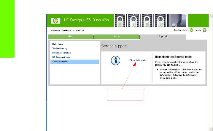
Troubleshooting
•Embedded Web Server: Support tab Service Support Printer Information.
Printer Information
Even if the Printer cannot print, the Information Pages are still accessible through the Embedded Web Server.
Main Characteristics
•Only available in English (except the current information page).
•From the Front Panel, you can choose to print ALL pages or just select the specific pages that are needed. If ALL pages are printed:
•Nesting is turned ON automatically (and turned OFF once all the pages have been printed).
•Nesting cannot be mixed with other jobs in the queue.
•Each page can be printed from the Web browser when using the Embedded Web Server.
•Each page can be sent by e-mail from the Web Browser when using the Embedded Web Server (File Send Page by E-mail).
•You can see the same information through the Front Panel or the Embedded Web Server.
20 Chapter 1 Troubleshooting
Loading...