


 Loading...
HP Designjet Z5200ps GP Photo Printer -
Service Manual
For HP Internal Use Only
©Copyright Hewlett-Packard Company 2010
This document contains proprietary information that is protected by copyright. All rights are reserved. No part of this document may be photocopied, reproduced, or translated to another language without the prior written consent of Hewlett-Packard Company.
First Edition, May 2010

Notices
Warranty
The information contained in this document is subject to change without notice.
Hewlett-Packard makes no warranty of any kind with regard to this material, including, but not limited to, the implied warranties of merchantability and fitness for a particular purpose.
Hewlett-Packard shall not be liable for errors contained herein or for incidental or consequential damages in connection with the furnishing, performance, or use of this material.
WARNING! The procedures described in this manual are to be performed by HP-qualified service personnel only.
Electrical Shock Hazard
Serious shock hazard leading to death or injury may result if you do not take the following precautions:
●Ensure that the ac power outlet (mains) has a protective earth (ground) terminal.
●Disconnect the Printer from the power source prior to performing any maintenance.
●Prevent water or any other liquids from running onto electrical components or circuits, or through openings in the enclosure.
Electrostatic Discharge
Refer to the beginning of Diagnostic Menu on page 73 of this manual, for precautions you should take to prevent damage to the Printer circuits from electrostatic discharge.
Safety Symbols
General definitions of safety symbols are given immediately after the table of contents.
WARNING! The Warning symbol calls attention to a procedure, practice, or the like, which, if not correctly performed or adhered to, could result in personal injury. Do not proceed beyond a Warning symbol until the indicated conditions are fully understood and met.
CAUTION: The Caution symbol calls attention to an operating procedure, practice, or the like, which, if not correctly performed or adhered to, could result in damage to or destruction of part or all of the product. Do not proceed beyond a Caution symbol until the indicated conditions are fully understood and met.
Content Management Department,
Barcelona Division,
Hewlett-Packard Espanola, S.A.
Avda. Graells, 501
08190 Sant Cugat del Valles
Spain
ENWW |
iii |
iv Notices |
ENWW |
Using this Manual
Purpose
This Service Manual contains information necessary to test, calibrate and service:
●HP Designjet Z5200 Photo Printer 44 inch (Model CQ113A)
For information about using this product, refer to the corresponding User and Quick Reference Guides.
Readership
The procedures described in this Service Manual are to be performed by HP Certified service personnel only.
Part Numbers
Part Numbers for Printer options, accessories and service parts are located in Parts and Diagrams on page 151.
Conventions
A small arrow  indicates a link to other parts of the Service Manual where you can find information related to the topic you are consulting.
ENWW |
v |
vi Using this Manual |
ENWW |

Table of contents
1 Ink Supplies Troubleshooting & Print Quality |
|
Introduction ........................................................................................................................................... |
2 |
Troubleshooting System Error Codes .................................................................................................. |
2 |
Performing a Service Test on a failed Assembly .................................................................................. |
2 |
Performing the Necessary Service Calibrations ................................................................................... |
2 |
Solving Ink Supplies Problems ............................................................................................................. |
3 |
Solving Print Quality Problems ............................................................................................................. |
3 |
Using the Front Panel ........................................................................................................................... |
3 |
The Printer does not Power ON ........................................................................................................... |
4 |
The Printer Continuously Rejects Printheads ....................................................................................... |
4 |
What to do if the Front Panel is blank .................................................................................................. |
5 |
Cover Sensors are not Working ........................................................................................................... |
6 |
The Line Sensor has Problems Detecting Media ................................................................................. |
6 |
Problems with Color Accuracy ............................................................................................................. |
6 |
Troubleshooting Media Jams/Printhead Crashes ................................................................................ |
6 |
Banding at variable extreme environmental conditions ........................................................................ |
7 |
Worm marks on HP Coated media with light area fills ......................................................................... |
7 |
Solving Media-Handling Problems ....................................................................................................... |
7 |
What to do when plastic parts on the Media Basket become damaged during printer setup ............... |
8 |
Solving Ink Supplies problems ............................................................................................................. |
9 |
Ink Cartridges ...................................................................................................................... |
9 |
Available Ink Cartridges ....................................................................................................... |
9 |
Printheads .......................................................................................................................... |
10 |
Available Printheads .......................................................................................................... |
10 |
General Information About the Ink Supplies ...................................................................... |
10 |
General Precautions When Handling Ink Supplies ............................................................ |
11 |
When Should You Replace the Ink Supplies? ................................................................... |
11 |
Ink Cartridge Levels, Information, and Replacement ......................................................................... |
11 |
Ink Cartridge Levels ........................................................................................................... |
11 |
Obtaining Ink Cartridge Information ................................................................................... |
12 |
Changing an Ink Cartridge ................................................................................................. |
13 |
Printhead Information, Replacement and Alignment .......................................................................... |
15 |
Obtaining Printhead Information ........................................................................................ |
15 |
Changing a Printhead ........................................................................................................ |
16 |
Aligning Printheads ............................................................................................................ |
18 |
Ink Cartridge and Printhead Status Messages ................................................................................... |
20 |
Ink Cartridge Status Messages .......................................................................................... |
20 |
ENWW |
vii |
Printhead status messages ............................................................................................... |
20 |
Solving Ink Supplies Problems ........................................................................................................... |
21 |
You Cannot Insert the Ink Cartridge Into the Printer .......................................................... |
21 |
You Cannot Insert the Printhead Into the Printer ............................................................... |
21 |
The front panel says to reset or replace a printhead ......................................................... |
21 |
Maintaining and Cleaning the Printheads ........................................................................................... |
22 |
Clean the printheads .......................................................................................................... |
22 |
Flex Contacts Cleaning Tool .............................................................................................. |
22 |
Print Quality ........................................................................................................................................ |
23 |
Print Quality Troubleshooting Actions ................................................................................ |
23 |
The Service Image Quality Diagnostic Print ....................................................................................... |
24 |
What is the Service Image Quality Diagnostic Print? ........................................................ |
24 |
Considerations for Printing the Diagnostic Print ................................................................ |
24 |
Printing the Diagnostic Print .............................................................................................. |
24 |
Reading the Diagnostic Print Results ................................................................................................. |
25 |
Diagnostic Part 1: Printhead Reliability .............................................................................. |
25 |
Diagnostic Part 2: Printhead Alignment ............................................................................. |
26 |
Diagnostic Part 3: Printheads & Paper Advance ............................................................... |
28 |
No Printing Defects Found in the Diagnostic Print ............................................................. |
29 |
The Advanced Diagnostic Prints ........................................................................................................ |
29 |
What are the Advanced Diagnostic Prints? ....................................................................... |
29 |
Printing the Advanced Diagnostics Print ............................................................................ |
30 |
Reading the Advanced diagnostic Print Results ................................................................................ |
30 |
Paper Advance .................................................................................................................. |
30 |
Printhead Alignment .......................................................................................................... |
33 |
Nozzle Health .................................................................................................................... |
34 |
Force Drop Detection ......................................................................................................... |
35 |
Troubleshooting Print Quality Problems ............................................................................................. |
36 |
Print Quality General Advice .............................................................................................. |
36 |
Horizontal Lines Across the Image (Banding) ................................................................... |
36 |
Lines are Missing, Too Thin, or Too Thick ......................................................................... |
37 |
Problems with Stepped Lines ............................................................................................ |
37 |
Lines are Printed Double or in Wrong Colors .................................................................... |
38 |
Lines are discontinuous ..................................................................................................... |
38 |
Lines are Blurred (Ink Bleeds from Lines) ......................................................................... |
39 |
Problems with Graininess .................................................................................................. |
39 |
Paper is not Flat ................................................................................................................. |
40 |
Print Scuffing or Scratching when Touched ....................................................................... |
41 |
Ink marks on the paper ...................................................................................................... |
41 |
Problems with the Edges of objects ................................................................................... |
42 |
Bronzing ............................................................................................................................. |
42 |
Black and white prints do not look neutral ......................................................................... |
43 |
Horizontal lines at the end of a cut sheet print ................................................................... |
43 |
Vertical lines of different colors .......................................................................................... |
43 |
White spots on the print ..................................................................................................... |
43 |
Problems with Color Accuracy ........................................................................................... |
43 |
Output Only Contains a Partial Print .................................................................................. |
44 |
viii |
ENWW |
Problems with Image Clipping ........................................................................................... |
44 |
||
Some objects are missing from the printed image ............................................................. |
45 |
||
A PDF file is clipped or objects are missing ....................................................................... |
45 |
||
2 System Error Codes |
|
|
|
Introduction |
......................................................................................................................................... |
|
46 |
Continuable and Non-Continuable Error Codes ................................................................................. |
47 |
||
System Error ................................................................................................Code Brief Descriptions |
47 |
||
System Error .............................................................................................Codes - Full Descriptions |
50 |
||
3 Diagnostic Menu |
|
|
|
Introduction ......................................................................................................................................... |
|
|
74 |
Diagnostics .......................................................................................................- Self Test |
74 |
||
Service Tests ................................................................................................................(Diagnostics) |
74 |
||
Entering .......................................................................................the Service Tests Menu |
76 |
||
...................................................................................................... |
1. |
Scan Axis |
76 |
................................................................................................... |
2. |
Paper Drive |
87 |
........................................................................................ |
3. |
Electronics Module |
90 |
........................................................................................ |
4. |
Carriage Assembly |
95 |
....................................................................................................... |
5. |
Sensors |
101 |
..................................................................................... |
6. |
Color Sensor (ESP) |
104 |
........................................................................... |
7. |
Ink Delivery System (IDS) |
106 |
............................................................................................ |
8. |
Service Station |
110 |
............................................................................................ |
9. |
I/O Information |
117 |
......................................................................................... |
10. Unit Information |
117 |
|
........................................................................................... |
11. EEROM Reset |
119 |
|
............................................................................... |
12. Set Unit Configuration |
120 |
|
................................................................................ |
13. Error 71:19 Recovery |
120 |
|
.......................................................................................................................................................... |
|
|
123 |
4 Service Menu |
|
|
|
Entering the ..................................................................................................Service Utilities Menu |
124 |
||
Introduction ...................................................................................................................... |
|
125 |
|
......................................................................................................................... |
|
|
126 |
1. .......................................................................................................... |
Turn Drive Roller |
126 |
|
2. ................................................................................................................ |
Purge Tubes |
128 |
|
3. ......................................................................................................................... |
Set SN |
|
130 |
4. ..................................................................................................... |
Reset Life Counters |
131 |
|
5. ............................................................................................................ |
Diagnostic Print |
132 |
|
6. ....................................................................................................... |
Set Date and Time |
132 |
|
7. ............................................................................................... |
Enable/Disable Firewall |
133 |
|
8. ........................................................................................ |
Enable/Disable Sleep Mode |
134 |
|
9. ................................................................................... |
SNMP Language Write Access |
135 |
|
10 .............................................................................................Borderless Cut Distance |
137 |
||
Service Calibrations ......................................................................................................................... |
|
138 |
|
Entering ..........................................................................the Service Calibrations Menu |
139 |
||
ENWW |
ix |
Scan Axis Calibration ....................................................................................................... |
139 |
Service Station Calibration .............................................................................................. |
140 |
Paper Advance Calibration .............................................................................................. |
140 |
Drop Detector Calibration ................................................................................................ |
145 |
Line Sensor Calibration ................................................................................................... |
146 |
Carriage PCA ................................................................................................................... |
149 |
Color Sensor (ESP) Calibration ....................................................................................... |
149 |
5 Parts and Diagrams |
|
Printer Support ................................................................................................................................. |
152 |
Center Covers (Front) ...................................................................................................................... |
153 |
Center Covers (Rear) ....................................................................................................................... |
154 |
Right Cover ...................................................................................................................................... |
155 |
Left Cover ......................................................................................................................................... |
156 |
Right Hand Assemblies .................................................................................................................... |
157 |
Left Hand Assemblies ...................................................................................................................... |
158 |
Carriage Assembly ........................................................................................................................... |
159 |
Scan-Axis Assemblies ...................................................................................................................... |
160 |
Paper Path Assemblies (Front) ........................................................................................................ |
161 |
Paper Path Assemblies (Rear) ......................................................................................................... |
162 |
Tools 1 .............................................................................................................................................. |
163 |
Tools 2 .............................................................................................................................................. |
164 |
Miscellaneous Parts ......................................................................................................................... |
165 |
6 Removal and Installation |
|
Introduction ....................................................................................................................................... |
169 |
Safety Precautions ........................................................................................................... |
169 |
Electrostatic Discharge (ESD) Precautions ..................................................................... |
169 |
Required Tools ................................................................................................................ |
169 |
Service Calibration Guide to Removal and Installation .................................................................... |
170 |
Using the Service Calibration Guide ................................................................................ |
170 |
The Service Calibration Matrix ......................................................................................... |
171 |
Performing the Service Calibrations and Diagnostic Tests .............................................. |
172 |
Window ............................................................................................................................................. |
174 |
Front Cover ...................................................................................................................................... |
177 |
Media Output Assembly ................................................................................................................... |
178 |
Right Front Trim ............................................................................................................................... |
179 |
Left Front Trim .................................................................................................................................. |
181 |
Right Ink Cartridge Door ................................................................................................................... |
182 |
Left Ink Cartridge Door ..................................................................................................................... |
183 |
Right Cover ...................................................................................................................................... |
185 |
Left Cover ......................................................................................................................................... |
188 |
Rear Tray ......................................................................................................................................... |
194 |
Rear Cover ....................................................................................................................................... |
195 |
Media Lever ...................................................................................................................................... |
196 |
Media Lever Position Sensor ........................................................................................................... |
198 |
x |
ENWW |
Cutter Assembly ............................................................................................................................... |
199 |
Right Rear Tray Support .................................................................................................................. |
200 |
Left Rear Tray Support ..................................................................................................................... |
201 |
Front Panel ....................................................................................................................................... |
203 |
Top Cover ......................................................................................................................................... |
205 |
Window Position Sensor .................................................................................................................. |
208 |
Ink Supply Tubes Support Rail ......................................................................................................... |
209 |
Service Station ................................................................................................................................. |
214 |
Drop Detector ................................................................................................................................... |
217 |
Aerosol Fan Assembly ..................................................................................................................... |
219 |
PrintMech PCA ................................................................................................................................. |
220 |
Pen to Paper Space (PPS) Solenoid ................................................................................................ |
221 |
Spindle ............................................................................................................................................. |
223 |
Left Spindle Holder ........................................................................................................................... |
224 |
Right Spindle Holder ........................................................................................................................ |
224 |
Clean Out Assembly ......................................................................................................................... |
225 |
Out Of Paper Sensor ........................................................................................................................ |
226 |
Left Roll Guide .................................................................................................................................. |
229 |
Right Roll Guide ............................................................................................................................... |
230 |
Encoder Strip (with spring and attachment nut) ............................................................................... |
231 |
Clean Encoder Strip Procedure ........................................................................................................ |
234 |
Encoder Strip .................................................................................................................................... |
236 |
Trailing Cable ................................................................................................................................... |
237 |
Carriage Assembly (with or without Trailing Cable) ......................................................................... |
244 |
Carriage Rear Bushing ..................................................................................................................... |
254 |
Belt Assembly ................................................................................................................................... |
256 |
Scan-Axis Motor ............................................................................................................................... |
257 |
Carriage Rail Oiler ............................................................................................................................ |
260 |
Color Sensor (ESP) .......................................................................................................................... |
262 |
Line Sensor ...................................................................................................................................... |
267 |
Carriage Cover (includes Carriage Latch) ........................................................................................ |
272 |
Carriage PCA ................................................................................................................................... |
276 |
Right Ink Supply Station ................................................................................................................... |
280 |
Left Ink Supply Station ..................................................................................................................... |
284 |
Ink Supply Tubes .............................................................................................................................. |
288 |
Formatter .......................................................................................................................................... |
296 |
Hard Disk Drive ................................................................................................................................ |
297 |
Electronics Module (Main PCA and PSU) ........................................................................................ |
298 |
Starwheel Assembly ......................................................................................................................... |
301 |
Print Zone Overdrive ........................................................................................................................ |
302 |
Left Spittoon ..................................................................................................................................... |
306 |
Encoder Disk and Encoder Sensor .................................................................................................. |
308 |
Media Advance Drive ....................................................................................................................... |
311 |
Pinchwheel Assembly ...................................................................................................................... |
314 |
Pinch Roller ...................................................................................................................................... |
319 |
Left Starwheel Lifter ......................................................................................................................... |
320 |
Right Starwheel Lifter ....................................................................................................................... |
322 |
ENWW |
xi |
Starwheel Motor ............................................................................................................................... |
325 |
Full Bleed Foam ............................................................................................................................... |
326 |
7 Preventive Maintenance |
|
Preventive Maintenance ................................................................................................................... |
328 |
Moisture on the Printer .................................................................................................... |
328 |
Noisy Carriage Bushing ................................................................................................... |
328 |
Belt Swelling .................................................................................................................... |
328 |
Cleaning the Printer ......................................................................................................... |
328 |
Carriage Assembly Lubrication ........................................................................................ |
328 |
General Cleaning ............................................................................................................. |
329 |
Cleaning the Drive Roller and Overdrive ......................................................................... |
329 |
Level of Printer Usage ..................................................................................................... |
329 |
Preventive Maintenance Kits ............................................................................................................ |
330 |
Preventive Maintenance Kit #1 ........................................................................................ |
330 |
Preventive Maintenance Kit #2 ........................................................................................ |
331 |
8 Printer menu Map |
|
xii |
ENWW |

1Ink Supplies Troubleshooting & Print Quality
●Introduction
●Troubleshooting System Error Codes
●Performing a Service Test on a failed Assembly
●Performing the Necessary Service Calibrations
●Solving Ink Supplies Problems
●Solving Print Quality Problems
●Using the Front Panel
●The Printer does not Power ON
●The Printer Continuously Rejects Printheads
●What to do if the Front Panel is blank
●Cover Sensors are not Working
●The Line Sensor has Problems Detecting Media
●Problems with Color Accuracy
●Troubleshooting Media Jams/Printhead Crashes
●Banding at variable extreme environmental conditions
●Worm marks on HP Coated media with light area fills
●Solving Media-Handling Problems
●What to do when plastic parts on the Media Basket become damaged during printer setup
●Solving Ink Supplies problems
●Ink Cartridge Levels, Information, and Replacement
●Printhead Information, Replacement and Alignment
●Ink Cartridge and Printhead Status Messages
●Solving Ink Supplies Problems
●Maintaining and Cleaning the Printheads
●Print Quality
●The Service Image Quality Diagnostic Print
ENWW |
1 |

●Reading the Diagnostic Print Results
●The Advanced Diagnostic Prints
●Reading the Advanced diagnostic Print Results
●Troubleshooting Print Quality Problems
Introduction
This chapter will guide you through the relevant steps to take when troubleshooting the printer.
Troubleshooting System Error Codes
Chapter 2, System Error Codes on page 46 contains a list of system error codes and their respective descriptions and recommended corrective actions. Only try one recommended action at a time and check if the error code has disappeared.
If you have an error code which is not documented in this Service Manual or you have an error which you cannot resolve, then report the error to the HP Response Center or the nearest HP Support Office. When reporting the error, have the following information ready:
●Model and Serial Number of the printer
●Which firmware revision the printer is using (See Note below). Check firmware in Utilities/
Statistics/Code rev.
●The complete error number (See Note below).
●The Service Configuration Print.
●The Current configuration sheet.
●Which software application the customer is using (name, version, etc.).
 NOTE: When reporting the System Error Code, make sure that you supply the full Error Code and the firmware version. Without this information, HP Support Personnel cannot help you.
Performing a Service Test on a failed Assembly
If possible, always perform a Service Test on the component/assembly that you are about to replace, just to make sure that is the component/assembly that has failed.
 NOTE: If the test on that component/assembly passes, you should NOT replace it.
For information on the Service Tests and how to use them see Diagnostic Menu on page 73 & Service Menu on page 124.
Performing the Necessary Service Calibrations
Is the printer calibrated correctly after replacing a component? For information on the Service Calibrations and how to use them see Chapter 5, Service Calibrations.
 NOTE: Remember that certain Calibrations are required even if an Assembly has been disassembled to gain access to another Assembly or Component.
2 |
Chapter 1 Ink Supplies Troubleshooting & Print Quality |
ENWW |
Solving Ink Supplies Problems
For information on solving Ink Supplies problems see Solving Ink Supplies problems on page 9 in this section.
Solving Print Quality Problems
For information on solving Print Quality problems see Print Quality on page 23 in this section.
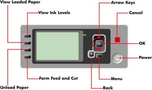
Using the Front Panel
Below is a diagram of the front panel.
Key Function
●Arrow Keys
Use the Arrow keys to scroll through a menu or toggle between YES or NO when prompted.
●Cancel
Use the Cancel key to abort or stop a procedure or reject test results.
●OK
Use the OK key to select a menu option.
●Power
Use the Power key to turn the printer ON and OFF.
●Menu
Use the Menu key to enter the main menu.
●Back
Use the Back key to go back to the previous menu or reject test results.
ENWW |
Solving Ink Supplies Problems 3 |
Service Key Combinations
●Diagnostic mode
With the printer OFF, press and hold the UP and OK keys. While holding the Up and OK keys down, press and hold the Power key to turn on the printer. Hold all three keys until the Power key stops flashing, usually about 5 seconds.
●Service Menu (Service Engineers Only)
From the main menu, press and hold the Up and Cancel keys.
●Service Menu (For users)
From the main menu, press and hold the Down and Cancel keys.
The Printer does not Power ON
1.Check that the power cord is connected correctly to the Printer and to the Power Socket.
2.Check that the Power Switch on the BACK of the Printer is in the ON position.
3.Check to see the LED on the Front Panel Power Switch are On.
4.Check that the Front-Panel Cable is correctly connected to the Electronics Module. Also make sure that the Front-Panel cable is not damaged.
5.Replace the Power Supply Unit  Refer Electronics Module (Main PCA and PSU) on page 298.
The Printer Continuously Rejects Printheads
1.Clean the flex contacts on the Printhead and in the Carriage Assembly using the Carriage Interconnect Wiper (Refer to Flex Contacts Cleaning Tool on page 22) and try again.
2.If ALL the Printheads are rejected (the status message on the Front Panel does NOT show "OK"
for ALL the Printheads) then perform the Electronic Module Test  Refer 3. Electronics Module on page 90.
4 |
Chapter 1 Ink Supplies Troubleshooting & Print Quality |
ENWW |

What to do if the Front Panel is blank
The LEDs of the formatter (visible through the cover) and the power supply can help you troubleshoot a problem when the Front Panel is blank.
1.The following image shows the Power Supply LED, looking through the cover.
2.The following image shows the Formatter LEDs, which are marked I, II and III.
▲Use the following table to interpret the LEDs and find the source of the problem. Remember that you should read these LEDs when you push the Power button. Some combinations may require the replacement of two or more components. In this case, always replace one component at a time. Test the printer to see if the problem has disappeared (check the LEDs again). If the same LED sequence continues, replace the next component indicated in the table.
|
Power |
Formatter |
Formatter |
Formatter |
Front Panel |
Solution (part replacement) |
|
Supply LED |
LED 1 |
LED 2 |
LED 3 |
Status |
|
|
|
|
|
|
|
|
1 |
Off |
Off |
Off |
Off |
Off |
Power Electronics Module (Main PCA and |
|
|
|
|
|
|
PSU) on page 298 |
|
|
|
|
|
|
|
2 |
On |
Off |
Off |
Off |
Off |
Main PCA Electronics Module (Main PCA |
|
|
|
|
|
|
and PSU) on page 298 |
|
|
|
|
|
|
|
3 |
On |
On |
Off |
N/A |
N/A |
Formatter Formatter on page 296 |
|
|
|
|
|
|
|
4 |
On |
On |
Off |
Off |
N/A |
Hard Disk Hard Disk Drive on page 297 |
|
|
(Flashing) |
|
|
|
|
|
|
|
|
|
|
|
5 |
On |
On |
On (flashing) |
Off |
N/A |
Hard Disk Hard Disk Drive on page 297 |
|
|
|
|
|
|
|
6 |
On |
On |
On |
Off |
N/A |
1. Formatter Formatter on page 296 |
|
|
|
|
|
|
2. Main PCA Electronics Module (Main |
|
|
|
|
|
|
PCA and PSU) on page 298 |
|
|
|
|
|
|
|
7 |
On |
On |
On |
On (flashing) |
N/A |
Main PCA Electronics Module (Main PCA |
|
|
|
|
|
|
and PSU) on page 298 |
|
|
|
|
|
|
|
ENWW |
What to do if the Front Panel is blank 5 |

8 |
On |
On |
On |
On |
Front Panel |
1. |
Front Panel Front Panel |
|
|
|
|
|
(Light on) |
|
on page 203 |
|
|
|
|
|
|
2. |
Formatter Formatter on page 296 |
|
|
|
|
|
|
3. |
Main PCA Electronics Module (Main |
|
|
|
|
|
|
|
PCA and PSU) on page 298 |
|
|
|
|
|
|
4. |
Front Panel Cable Front Panel |
|
|
|
|
|
|
|
on page 203 |
|
|
|
|
|
|
|
|
9 |
On |
On |
On |
On |
Off |
Front Panel Front Panel on page 203 |
|
|
|
|
|
|
|
|
|
Cover Sensors are not Working
1.Perform the Sensors Test  Refer 5. Sensors on page 101.
2.Check if the cable for the faulty sensor is not damaged and is connected correctly.
3.Replace the faulty Sensor.
The Line Sensor has Problems Detecting Media
1.Check the type of media that is being used since the Line sensor may have problems detecting transparent media or some types of Non-HP media. Try loading white HP media in to the Printer and check if the Line sensor detects it.
2.The Line Sensor is not calibrated correctly. Perform the Line Sensor Calibration  Refer Line Sensor Calibration on page 146.
3.The Line Sensor is damaged or faulty. Replace the Line Sensor  Line Sensor on page 267.
Problems with Color Accuracy
The Color Sensor (ESP) is a powerful tool unique to the Z series printers to maintain color accuracy. If you notice any problems with colors, perform the Color Sensor (ESP) calibration. Refer to Color Sensor (ESP) Calibration on page 149.
Troubleshooting Media Jams/Printhead Crashes
The failure modes "media jam" and "head crash" are grouped together because in many cases a media jam causes the media to lift up into the Carriage path and cause a Printhead crash, thus causing many media jam failures to be reported as head crashes.
1.Did the media jam occur when loading media?
●If the client has had media jams, it is common for pieces of media to get stuck in the media path. Clear the media path.
 NOTE: When clearing a media jam, sometimes media is stuck in the paper path. To clear this, you must lift the Media Lever and insert thicker media into the paper path to push out the media that is still stuck there.
2.Is the customer using non-HP media?
●The use of non-HP media can easily be the cause of media jams and head crashes (especially head crashes because HP media is specially formulated to avoid cockle, one of the primary causes of head crashes). If the media is not HP approved, advise the customer to use HP media and check to see if the problem is now solved.
6 |
Chapter 1 Ink Supplies Troubleshooting & Print Quality |
ENWW |
Banding at variable extreme environmental conditions
Since the Accuracy Calibration has been done at normal environmental conditions, printing in extreme environmental conditions will cause banding because the advance of the Media Advance Roller does not correspond to the same conditions that the calibration was done in. To solve the problem, try the following:
Perform the Accuracy Calibration in the new environmental conditions (Refer to the User’s Guide).
Worm marks on HP Coated media with light area fills
Light bands (S-shaped) in Paper axis direction where light area fills are printed, causing unacceptable Image Quality defect.
●Print the Service Configuration Print and check if the level of Humidity is very low (below 30%). Increasing humidity may help in reducing the severity of the problem.
 NOTE: The media is causing the problem and NOT the Printer. Do not attempt to try and replace Printer parts to solve this problem.
Solving Media-Handling Problems
The Front Panel indicates that media is misaligned or incorrectly positioned.
Roll media
●The roll may be loaded the wrong way. The paper should load over the roll toward you.
●Check that the paper is correctly loaded onto the spindle.
●The paper may be loaded at an angle. The right-hand edge must be aligned with the blue line on the Print Platen.
 NOTE: Ensure that the paper is wrapped tightly on the roll. This is a very important step to remember because if this is not done, the media may be loaded at an angle, causing the media to be rejected.
Sheet media
●Always load sheet media using the Rear Input Tray. Do NOT load the media as you would load roll media.
●It must be loaded with the right-hand edge against the blue line on the Print Platen.
●The media may be crumpled or warped or may have irregular edges.
●If hand-cut media is used, the edges may not form a right-angle or they may be rough. If possible, hand-cut media should not be used. Only purchased sheet media should be used in the Printer.
●If you have problems with paper jams, check that the Overdrive is not obstructed by bits of paper or using the Turn Drive Roller Service Utility  1. Turn Drive Roller on page 126.
ENWW |
Banding at variable extreme environmental conditions |
7 |

What to do when plastic parts on the Media Basket become damaged during printer setup
The following information explains what to do if one or more of the back plastic brackets or the Basket Tube becomes broken. The information helps to identify which service parts to order as replacements.
There are three plastic parts that could break during printer installation and need replacing. Use the pictures below to identify with the customer which part needs replacing (numbers 1, 2 or 3).
8 |
Chapter 1 Ink Supplies Troubleshooting & Print Quality |
ENWW |
Solving Ink Supplies problems
What are Ink Supplies?
For each of the ink colors used in the printer, there are two components, the Printhead and Ink Cartridge. These components are called Ink Supplies.
Ink Cartridges
The printer's Ink Cartridges provide ink to the Printheads. The color Ink Cartridges supplied with the printer have a capacity of 69ml but optional 130 ml and 300 ml are also available.
The Ink Cartridges require no maintenance or cleaning. As long as each Ink Cartridge is inserted correctly into its slot, the ink will flow to the Printheads. Because the Printheads control the amount of ink transferred to the page, you will continue to see high quality printing results that require no maintenance or cleaning. As long as each Ink Cartridge is inserted correctly into its slot, the ink will flow to the Printheads. Because the Printheads control the amount of ink transferred to the page, you will continue to see high quality printing results even when the ink levels are getting low.
The front panel displays the status of the Ink Cartridge. Using the front panel, detailed information can be checked on the Ink Cartridges.
Available Ink Cartridges
Color |
Part number 69ml |
Part number 130ml |
Part number 300ml |
|
|
|
|
HP 70 Matte Black |
C9436A |
C9448A |
CN635A |
|
|
|
|
ENWW |
Solving Ink Supplies problems 9 |

HP 70 Photo Black |
C9437A |
C9449A |
CN633A |
|
|
|
|
HP 70 Light Gray |
C9439A |
C9451A |
CN634A |
|
|
|
|
HP 70 Cyan |
C9440A |
C9452A |
CN636A |
|
|
|
|
HP 70 Magenta |
C9441A |
C9453A |
CN629A |
|
|
|
|
HP 70 Yellow |
C9442A |
C9454A |
CN630A |
|
|
|
|
HP 70 Light Magenta |
C9443A |
C9455A |
CN631A |
|
|
|
|
HP 70 Light Cyan |
C9389A |
C9390A |
CN632A |
|
|
|
|
Printheads
The Printheads are extremely durable and do not need to be replaced every time an Ink Cartridge is replaced. They are independent of the Ink Cartridges and will continue giving excellent image quality results even if the Ink Cartridges are low on ink.
If you notice a decline in print quality such as lines or dots missing from text/graphics, go to Troubleshooting Print Quality Problems on page 36.
Available Printheads
|
Printhead Type |
Part number |
|
|
|
HP 70 Matte Black & Cyan |
C9404A |
|
|
|
|
HP 70 |
Light Magenta & Light Cyan |
C9405A |
|
|
|
HP 70 Magenta & Yellow |
C9406A |
|
|
|
|
HP 70 |
Photo Black & Light Gray |
C9407A |
|
|
|
General Information About the Ink Supplies
For optimum results from the printer and modular ink delivery system always follow these guidelines when handling the ink supplies:
●Always install the Ink Cartridges and Printheads before the expiration date, which is on the packaging.
●Install Ink Cartridges and Printheads in their color-coded slots.
●Follow the instructions on the front panel of the Printer during installation.
●Avoid unnecessary removal of the Ink Cartridges and Printheads.
10 Chapter 1 Ink Supplies Troubleshooting & Print Quality |
ENWW |

●When turning off the Printer always use the power Off button on the front panel. The Printheads are then stored correctly which prevents them from drying out.
●The Ink Cartridges should never be removed while the printer is printing. They should only be removed when the printer is ready for you to replace them. The front panel will guide you through the removal and installation procedure.
General Precautions When Handling Ink Supplies
Use the following precautions when handling Ink Supplies:
 NOTE: Do not touch, wipe or attempt to clean the printhead nozzles. This can damage the printhead.
●Handle the ink supplies with care. In particular the Printhead, which is a high precision device and must be handled carefully.
●Do not touch the Printhead nozzles.
●Do not put the Printhead down on the nozzles.
●Do not be rough when handling the Printheads. Always set them down gently.
●Do not drop the Printheads.
●Proper handling will assure optimum performance throughout the Printhead life.
●Do not touch the end of the Ink Cartridge which is inserted into the printer as there may be a small amount of ink on the connection.
●Avoid storing partially used Ink Cartridges on their ends.
When Should You Replace the Ink Supplies?
When to change the ink supplies is mostly determined by you with guidance from the front panel. In conjunction with the messages displayed in the front panel and the message explanations in this chapter, you will be able to choose for yourself when is the right time to change the ink supplies.
The Printer will also display the ink level and will tell you when the ink supply is low on ink. This means you have constantly updated information about the ink supplies.
Ink Cartridge Levels, Information, and Replacement
Ink Cartridge Levels
The front panel displays Ink Levels shown as level bars. These bars represent how much ink is remaining in the Ink Cartridges: as ink is used up the bars get shorter in length.
There are two methods for checking the ink levels of your Ink Cartridges.
“View Ink Levels” Direct Access Key
●Pressing the “View ink levels” direct access key on the Front Panel will immediately show you the ink levels. For more information about direct access keys, refer Using the Front Panel on page 3.
ENWW |
Ink Cartridge Levels, Information, and Replacement 11 |
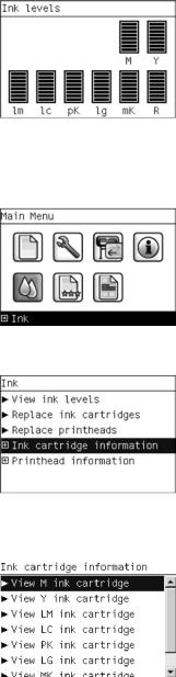
“View Ink Levels” from the ink menu
●Choosing the View ink levels options from the Ink menu will immediately show you the ink levels:
Obtaining Ink Cartridge Information
1.Scroll to the Ink Menu icon and press OK
2.In the Ink Menu submenu, scroll to Ink cartridge information and press OK
3.In the Ink cartridge information submenu, scroll to the Ink Cartridge that you want information on and press OK.
12 Chapter 1 Ink Supplies Troubleshooting & Print Quality |
ENWW |
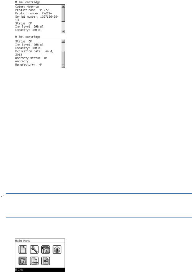
4.The front panel displays information on the selected Ink Cartridge. Use the Arrow keys to scroll through the information.
The information supplied is:
●The make of the Ink Cartridge.
●The product number of the Ink Cartridge.
●The serial number of the Ink Cartridge.
●The current status of the Ink Cartridge.
●The current ink level of the ink cartridge in milliliters.
●Original capacity of the ink cartridge in milliliters.
●The manufacturer of the Ink Cartridge (hp is recommended).
●The current warranty status of the Ink Cartridge.
Changing an Ink Cartridge
There are two occasions when you need to remove an ink cartridge:
●The ink cartridge is very low and you want to replace it with a full cartridge for unattended printing (you can use up the remaining ink in the first cartridge at a more convenient time).
●The ink cartridge is empty or faulty, and you must replace it to continue printing.
 NOTE: Do not try to remove an ink cartridge while printing. Remove an ink cartridge only if you are ready to insert another one.
Make sure the printer wheels are locked (the brake lever is pressed down) to prevent the printer from moving.
Change an ink cartridge using the following procedure:
1. Scroll to the Ink Menu icon and press OK.
ENWW |
Ink Cartridge Levels, Information, and Replacement 13 |

2.In the Ink Menu submenu, scroll to Replace ink cartridges and press OK.
3.The front panel displays the status of the Ink Cartridges.
4.Press OK to continue.
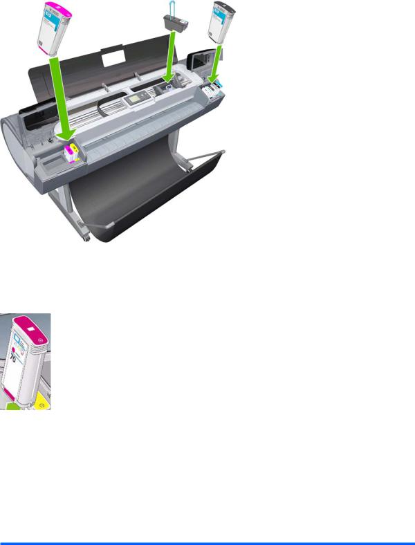
5.Open the relevant Ink Cartridge cover for the Ink Cartridge you want to replace.
6.Pull the required Ink Cartridge straight up to remove it from the printer.
7.The front panel indicates the missing Ink Cartridge.
8.Before removing the cartridge from its wrapping, shake it vigorously.
9.Unwrap the new ink cartridge, find the label identifying the ink color. Check that the letter or letters marking the empty slot, matches the letter or letters on the cartridge label.
10.Insert the ink cartridge into its slot.
11.Push the cartridge into the slot until it snaps into position. You should hear a beep and see confirmation that the cartridge has been inserted.
12. When all cartridges have been inserted, close the cover.
14 Chapter 1 Ink Supplies Troubleshooting & Print Quality |
ENWW |

Printhead Information, Replacement and Alignment
Obtaining Printhead Information
1.Scroll to the Ink Menu icon and press OK.
2.In the Ink Menu submenu, scroll to Printhead information and press OK.
3.In the Printhead Information submenu, scroll to the Printhead that you want information on and press OK.
4.The front panel displays information on the selected Printhead.
The information supplied is:
●The make of the printhead.
●The product number of the Printhead.
●The serial number of the Printhead.
●The current status of the printhead.
●How much ink has been fired (consumed) by the printhead.


 NOTE: It is possible for a printhead to consume more than one Ink Cartridge.
●The current warranty status of the Printhead.
ENWW |
Printhead Information, Replacement and Alignment 15 |

Changing a Printhead
1.Scroll to the Ink Menu icon and press OK.
2.In the Ink Menu submenu, scroll to Replace printheads and pressOK .
3.The printer moves the Carriage to the correct position to replace Printheads.
 NOTE: If the carriage is left in the removal position for more than three minutes without inserting or removing any printheads, it will try to move back to its normal position at the right-hand end.
4.When the carriage has stopped moving, the front panel display will prompt you to open the window and lift the carriage cover.
5.Open the window.
6.Lift the Carriage cover to access the printheads.
7.Lift the blue handle and pull the Printhead straight up out of the Carriage.
16 Chapter 1 Ink Supplies Troubleshooting & Print Quality |
ENWW |
Loading...