


 Loading...
ELPMB22 ELPMB23
ELPMB22/ELPMB23
Ceiling Mount ELPMB22/ELPMB23 Instruction Manual
Fixation au plafond ELPMB22/ELPMB23 Guide de l’utilisateur Deckenhalterung ELPMB22/ELPMB23 Bedienungsanleitung
Manuale dell’utente per la staffa di montaggio ELPMB22/ELPMB23 Manual de usuario de la consola para montaje ELPMB22/ELPMB23
1
●ELPMB22 ELPMB23
11 4
●ELPMB22
/
2

ELPMB22 3.5kg ELPMB23 3.4kg
ELPMB22 W342 × D210 × H150 mm ELPMB23 W270 × D139 × H150 mm
1
1-1
kg
3
1-2
ELPMB22 |
ELPMB23 |
|
|
|
|
|
|
|
|
|
(4 M4 × 12)/ |
|
|
|
4 |
/ |
|
|
4 |
|
|
|
|
|
|
1-3
ELPMB22
|
|
|
/ |
|
|
|
||
2 |
||
|
||
|
||
|
|
|
|
|
ELPMB23
|
|
|
/ |
|
|
|
||
2 |
||
|
||
|
||
|
||
|
|
|
|
|
4

1-4
|
|
|
|
|
|
|
|
|
20m |
|
|
|
|
|
|
||
|
||
|
||
|
||
|
||
|
||
|
||
|
|
|
|
|
2
2-1
1
可動状態になっていない場合は、次の手順で可動状態にしてください。
 180
180 


|
|

5

2 2
30
2-2
(1) 4
16 14
159 200
81
160
|
|
150 |
|
ELPMB22 ELPMB23
10 3
11 4
6

2-3
1 2 4
4 /
4 /4
の取扱説明書を確認し、そこに記載されている取付け部を利用して固定 してください。
7
2-4
さい。
(2)2
8

2-5
● 130mm ELPMB22 /100mm ELPMB23 |
|
|||
|
|
|
|
|
|
|
|
|
|
|
|
|
|
|
|
|
|||
|
|
|||
|
||||
|
|
|||
|
|
|||
1 4 2 (A)
合わせ、レンズの位置を調整する
3 4
|
(A) |
|
|
2-6
●360
●/ ± 18
9
1 2 3 4 5 2 6
1 6
2 4 |
5 |
|
|
3 |
|
|
|
3
1 2
|
|
|
|
|
|
|
|
|
|
|
|
|
|
|
11 4
ト・ボルト等はM12
10
4
ELPFP13/ELPFP14
|
|
|
|
|
|
|
|
ELPFP13 |
|
|
|
|
|
|
|
||
|
|
|
|
|
|
|
|
|
|
|
|
|
|
|
|
|
|
|
|
|
|
|
|
|
||
|
|
|
|
|
|
668mm 918mm |
||
|
|
|
|
|
|
|
|
|
|
|
|
|
|
|
|
|
50mm |
|
|
|
|
|
|
|
|
ELPFP14 |
|
|
|
|
|
|
|||
|
|
|
|
|
|
|
|
918mm 1168mm |
|
|
|
|
|
|
|
|
|
|
|
|
|
|
|
|
|
50mm |
|
|
|
|
|
|
|
|
|
|
|
|
|
|
|
|
|
|
|
|
|
|
|
|
|
|
|
|
|
|
|
|
|
|
|
|
|
|
|
|
|
|
|
|
|
|
|
|
|
|
|
|
|
|
11

Introduction
This product is for mounting an Epson Multi-Media Projector on the ceiling.
ELPMB22 is for medium-size projectors and ELPMB23 is for small projectors. See our website or product catalog to find out which model can be used to mount your projector.
To adjust the height of where the projector is installed, purchase a separate extension pipe with height adjustment function.
→ For details, see "4 Extension Pipe" on page 11.
To ensure the safe use of this product, read this instruction manual carefully and keep it for future reference.
Epson accepts no responsibility for any damage or injury caused by incorrect mounting, assembly or handling.
The assembly and mounting illustrations show ELPMB22. The design of the actual product may differ from that shown in the illustrations.
Specifications are subject to change without notice.
Safety Precautions
The warning mark shown below is used throughout this instruction manual to ensure correct use and to prevent personal injury or property damage. Make sure you understand these warnings when reading this instruction manual.
 Warning
Incorrect handling resulting from ignoring a warning mark could result in serious injury or even death.
Features
Ball joint structure enables angle adjustment
Adjust the angles of horizontal rotation, vertical tilt and sideways tilt.
Easy mount/detach action simplifies access to the projector
Mount and detach the projector from the ceiling mount easily.
Scale sticker makes lens center alignment easy
Move the lens center horizontally in relation to the screen using the scale sticker as a guide.
2

Specifications
Weight
ELPMB22: 3.5 kg
ELPMB23: 3.4 kg
Dimensions
ELPMB22: W 342 × D 210 × H 150 mm
ELPMB23: W 270 × D 139 × H 150 mm
1 Before Assembly and Installation
1-1 Safety Precautions
 Warning
This product is sold on the assumption that the installation work will be performed by a specialist with the required technical know-how and ability. It should not be installed by anyone else.
Assemble the various parts using the appropriate methods to ensure sufficient strength.
Tighten the screws firmly.
Incomplete assembly could cause the projector and ceiling mount to fall and cause injury.
 Warning
When a projector is attached to the ceiling mount, their combined weight may be as much as 10 to 20 kilograms. Before starting the installation, carefully check the construction, material, and strength of the ceiling and use the most appropriate methods to prevent the projector from falling.
English
3

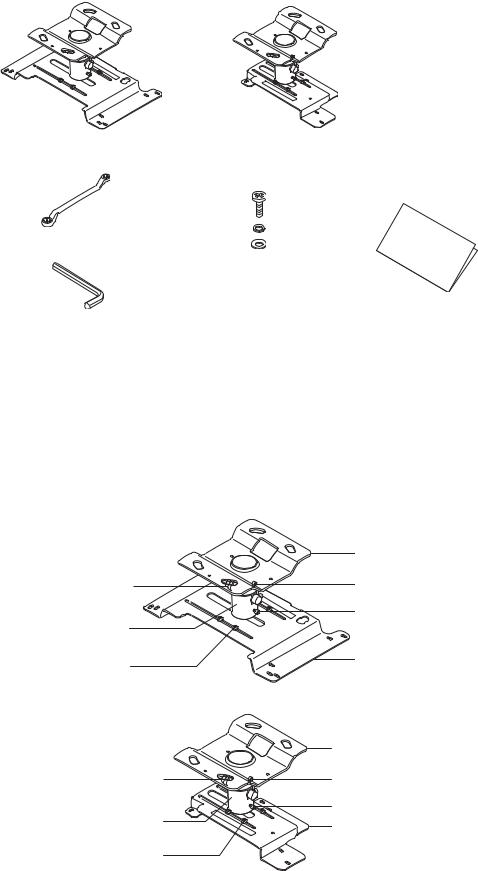
1-2 Checking the Package Contents
Open the box and check that nothing is missing.
ELPMB22 ceiling mount |
ELPMB23 ceiling mount |
Offset wrench |
|
|
|
|
Projector mounting |
|
|
|
screws: 4 pcs. (M4 × 12)/ |
|
|
|
lock washers: 4 pcs./ |
Instruction manual |
|
|
plain washers: 4 pcs. |
||
Hexagon wrench |
(this manual) |
||
|
•Only use the projector mounting screws provided to install the projector plate onto the projector.
•Prepare the necessary tools before starting.
1-3 Names of Parts
ELPMB22
|
Ceiling plate |
Tilt adjusting screw/ |
Plate securing screws |
screw cap |
(2 pcs.) |
Ball joint |
Tilt fixing screws (2 pcs.) |
|
|
Lens alignment |
Projector plate |
screws (4 pcs.) |
|
ELPMB23 |
|
Tilt adjusting screw/ screw cap
Ball joint
Lens alignment screws (4 pcs.)
Ceiling plate
Plate securing screws
(2 pcs.)
Tilt fixing screws (2 pcs.) Projector plate
4

1-4 Installing the Projector
•Install the projector away from fluorescent lighting, air conditioners and other electrical items. Failure to do so can cause the remote control to malfunction.
•To limit the effect of external noise, we recommend that you position the projector so that the cable connecting it to a computer or other device is no longer than 20 meters.
•The projector should be installed in a location that is free of dust and moisture to prevent the lens and internal optical parts from becoming dirty.
•Do not install the projector in a location beyond its operating temperature range.
Doing so can cause it to malfunction.
•Closing the curtains in a bright room makes the projected image easier to see.
2 Assembly and Installation
2-1 Removing the Ceiling Plate from the Projector Plate
(1)When you open the package, make sure the ball joint can be moved.
(The tilt adjusting screw and tilt fixing screws are loose when the product leaves the factory.)
If the ball joint cannot be moved, perform the following steps.
 Remove the screw cap (protruding type) from the tilt adjusting screw.
  Use the offset wrench provided to loosen the tilt adjusting screw.
•The tilt adjusting screw is designed to tighten again when turned more than 180 degrees.
•There is no need to loosen the screw on the opposite side of the tilt adjusting screw.
 Use the hexagon wrench to loosen the two tilt fixing screws.
Moveable
 Screw cap
Tilt adjusting screw |
Ball joint |
Tilt fixing screws (2 pcs.) |
|
English
5

(2)Remove the two plate securing screws with the hexagon wrench and remove the ceiling plate from the projector plate.
Rotate the ceiling plate about 30 degrees to the right and lift it.


 Ceiling plate
Plate securing screw
|
Plate securing screw |
Projector lens side |
Projector plate |
|
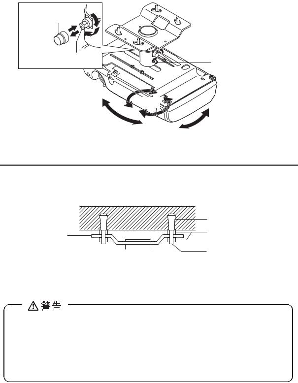
2-2 Fitting the Ceiling Plate to the Ceiling
(1)Secure the ceiling plate to the ceiling by putting screws or nuts through the four oblong holes.
Ceiling contact area dimensions (mm)
16 |
14 |
Oblong holes |
|||
|
|
|
|
|
|
|
|
|
|
|
|
159 200
81
160
Projector lens |
Ceiling plate |
150 |
side |
• The illustration shows ELPMB22. ELPMB23 has the same dimensions.
•When installing the ceiling mount on a concrete ceiling, use anchors and bolts.
→For details, see "3 Installing on a Concrete Ceiling" on page 10.
•To adjust the height of where the projector is installed, purchase a separate extension pipe with height adjustment function.
→For details, see "4 Extension Pipe" on page 11.
6

2-3 Fitting the Projector Plate to the Projector
(1)Turn over the projector so that the operating panel faces downwards.
(2)Use the four projector mounting screws provided to attach the projector plate to the projector.
There are several oblong holes in the projector plate. Place the screws through the holes that align with your projector and tighten them.
Projector mounting screws (4 pcs.)/lock washers (4 pcs.)/plain washers (4 pcs.)
Projector plate
Projector lens side
Projector operating panel side
• The illustration may differ depending on the kind of projector.
 Warning
Always use the screws provided to secure the projector. After tightening the screws check carefully that they are tight.
Firmly fix the projector to the ceiling mount with a sufficiently strong safety wire or belt to prevent it from falling. (Read the instruction manual of the projector to confirm which part of the projector can be to attach a safety wire or belt.)
Applying a screw-locking adhesive or lubricant, oil and so on to the projector where it is fixed to the ceiling mount can make the case crack and the projector fall, leading to damage or injury. Do not use any sort of adhesive, lubricant, or oil when installing or adjusting the ceiling mount.
English
7

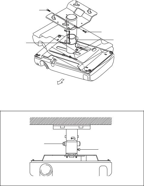
2-4 Fitting the Projector Plate to the Ceiling Plate
(1)Insert the ball joint of the projector plate into the ceiling plate.
Put the two protrusions on the ball joint into the grooves of the ceiling plate.
Fit the plates together so that the ball joint is in the direction illustrated (Front view).
(2)Tighten the two plate securing screws firmly with the hexagon wrench provided.
Plate securing screw

 Plate securing screw
Ball joint
Protrusions (2 pcs.)
Projector lens side
Front view
Tilt adjusting screw/
screw cap (Left side) 


 Tilt fixing screws
 (Right side/Rear side)
8

2-5 Aligning the Projector Lens Center
Moving the projector plate horizontally enables you to align the center of the ceiling mount (the ball joint) and the center of the projector lens.
Horizontal adjustment range: 130 mm (ELPMB22)/100 mm (ELPMB23)
 Warning
Hold the projector carefully from below during adjustment.
Retighten all screws after adjustment. If they are not sufficiently tight the projector may fall.
(1) |
Loosen the four lens alignment screws using the hexagon wrench |
|
|
|
|
provided. |
|
|
|
(2) |
Adjust the lens position by moving the projector plate horizontally until |
|
|
|
English |
||||
|
the measurement on the scale sticker (measurement (A) in the |
|||
|
|
|
||
|
illustration) equals the measurement for your projector shown on our |
|
|
|
|
website. |
|
|
|
(3) |
Fully tighten the four lens alignment screws using the hexagon wrench |
|
|
|
|
provided. |
|
|
|
Scale sticker
(A) |
Horizontal |
Lens alignment screws (4 pcs.) |
|
|
movement |
|
2-6 Adjusting the Angle
The ball joint structure makes it simple to fix the projector in any position within the installation angle range.
Horizontal rotation adjustment range: 360 degrees in any direction
Vertical tilt and sideways tilt adjustment range: ±18 degrees
 Warning
Hold the projector carefully from below during adjustment.
Retighten all screws after adjustment. If they are not sufficiently tight the projector may fall.
9
Loading...