


Before use
Installation
Connections
Projection
Useful Functions
Adjustments and
Setting
Using the EasyMP.net
Software
Troubleshooting
Maintenance
Others

Accessory Verification
Check to confirm that the following items are included in the package when removing the projector and accessories from the box. Contact your dealer if any items are found to be missing.
· Projector |
· Remote Control |
· 2AA Batteries for |
Lens Cover with string |
|
the remote control |
|
|
(three-cell alkaline manga- |
|
|
nese batteries) |
The NL model is not fitted with a lens or lens cover.
· Power Cord |
· Computer Cable |
· Computer Cable |
· Audio Cable |
|
|
(mini D-Sub |
|
|
|
15-pin/5BNC) |
|
· RCA Audio Cable |
· RCA Audio Cable |
· Main Cable |
· USB Mouse Cable |
(Yellow) |
(Red/White) |
|
|
· PS/2 Mouse Cable |
· Serial Mouse Cable |
· Mac Mouse Cable |
· Mac Serial Cable |
PS/2 MOUSE |
SERIAL MOUSE |
MAC MOUSE |
MAC SERIAL |
|
|
|
|
· PC Serial Cable |
· EasyMP.net Soft- |
· Owner’s Manual |
· 16MB Compact |
PC SERIAL |
ware CD-ROM |
(this document) |
Flash Card+Card |
|
|
Adapter |
|
|
|
|
|
· EasyMP.net User’s |
· Warranty Card |
|
|
Guide |
|
|
|
■ Features
● Crystal clear screen
Clarity has been vastly improved.
Provides crystal clear projections even in bright areas, perfect for presentation purposes.
● Wide range of display resolution
Uses a newly-developed high resolution liquid crystal panel. (1024×768)
● Compact and light
A compact body makes it easy for carrying around. (approximately 9.1Kg)
● Beautiful video images
The three-dimensional Y/C separation and smooth motion I/P conversion technology provide vivid video images.
● DVI-D port* that supports digital output
Fitted with a DVI-D Port for digital input purposes. This can also be connected to a computer’s digital output port.
● The EasyMP.net function, particularly strong with computer link-ups.
In addition to performing presentations with the data contained on the memory card inserted into the PCMCIA card slot, it is also possible to control the presentation from a computer connected to a LAN.
Features - 1

■ Contents |
|
Accessory Verification |
1 |
Features |
1 |
Contents |
2 |
Using this manual |
7 |
Symbol displays ................................................................... |
7 |
Safety Precautions |
8 |
Before using this equipment |
13 |
Parts, Names and Operations |
13 |
Projector ............................................................................. |
13 |
Remote Control .................................................................. |
18 |
Range of Remote Control Operations ................................ |
21 |
Inserting the Remote Control Batteries .............................. |
22 |
Installation |
23 |
Installation Procedure |
23 |
Installation example ........................................................... |
23 |
Screen size and projection distance .................................. |
24 |
Projection angles ................................................................ |
26 |
Connections |
27 |
Connecting the projector to a computer |
27 |
Eligible computers .............................................................. |
27 |
In the case of the mini D-Sub 15 pin .................................. |
29 |
In the case of 5BNC |
|
(When connected to the second computer) ....................... |
31 |
In the case of DVI-D* ......................................................... |
32 |
Sound connection .............................................................. |
33 |
2- Contents

Connecting external monitors ............................................ |
34 |
Connecting up the mouse (wireless mouse function) ........ |
35 |
Connecting the video equipment |
37 |
In the case of composite image signals ............................. |
37 |
In the case of S image signals ........................................... |
37 |
In the case of component (color differential*) |
|
image signals ..................................................................... |
38 |
In the case of the digital tuner's D output port .................... |
39 |
In the case of RGB image signals ...................................... |
40 |
Projecting |
41 |
Projection |
41 |
Preparations ....................................................................... |
41 |
Commencing projection ..................................................... |
42 |
Ending |
45 |
Adjusting the projection position |
47 |
Feet adjustments ................................................................ |
47 |
Adjusting the projection size |
48 |
Zoom adjustment ............................................................... |
48 |
Keystone adjustment .......................................................... |
49 |
Picture Quality Adjustment |
50 |
Focus adjustment ............................................................... |
50 |
Auto adjustment |
|
(when projecting computer images) ................................... |
50 |
Tracking adjustments |
|
(when projecting computer images) ................................... |
51 |
Synchronization adjustments |
|
(when projecting computer images) ................................... |
51 |
Calling out adjustment values |
|
(when projecting computer images) ................................... |
51 |
Introduction of Functions |
52 |
Contents- 3

Useful Functions |
53 |
Useful Functions |
53 |
Help Function ..................................................................... |
53 |
Projection Cutting |
55 |
A/V Mute Function .............................................................. |
55 |
Freeze Function ................................................................. |
55 |
Switching Image Sizes |
56 |
Enlarging Images (E-zooming function) |
58 |
Effect Function |
59 |
Cursor/Stamp ..................................................................... |
59 |
Box ..................................................................................... |
59 |
Spotlight ............................................................................. |
60 |
Bar ..................................................................................... |
61 |
Cancelling effects ............................................................... |
61 |
P in P Function |
62 |
Adjustments and settings |
63 |
Volume Adjustment |
63 |
Menu Configuration |
64 |
Menu items ......................................................................... |
64 |
Menu Operations |
66 |
Operation method .............................................................. |
66 |
Setting items ...................................................................... |
68 |
Image capture .................................................................... |
73 |
User logo registration ......................................................... |
75 |
4- Contents

Using the EasyMP.net Software |
77 |
Introduction of EasyMP.net Software |
77 |
Presentation support software ........................................... |
77 |
EasyMP.net PC applications .............................................. |
78 |
Installation |
79 |
Operating Environment ...................................................... |
79 |
Installation .......................................................................... |
80 |
Reading the User’s Guide .................................................. |
81 |
Computer Connections |
82 |
Serial Connections ............................................................. |
82 |
Troubleshooting |
84 |
Troubleshooting |
84 |
Operation Indicator ............................................................. |
84 |
Lamp Indicator ................................................................... |
85 |
Temperature Indicator ........................................................ |
86 |
When the Indicators Provide No Help |
87 |
The image is not projected ................................................. |
87 |
The image is out of focus ................................................... |
89 |
The image is distorted ........................................................ |
90 |
The image color is bad ....................................................... |
91 |
The image is dark ............................................................... |
91 |
No sound ............................................................................ |
92 |
The remote control won’t work ........................................... |
92 |
The projector will not switch off |
|
(after the [Power] button has been pressed) ...................... |
93 |
EMP Link V will not function ............................................... |
93 |
Contents- 5

Maintenance |
94 |
Cleaning the projector, Cleaning the lens, |
|
Cleaning the Air Filter |
94 |
Cleaning the projector ........................................................ |
95 |
Cleaning the lens ............................................................... |
95 |
Cleaning the Air Filter ......................................................... |
95 |
Replacing the Air Filter |
96 |
Replacement method ......................................................... |
96 |
Replacing the lamp |
97 |
Replacement method ......................................................... |
98 |
Resetting the lamp illumination time .................................. |
99 |
Others |
100 |
Optional Parts |
100 |
Terminology |
101 |
Specifications |
103 |
Check Sheet |
104 |
World-Wide Warranty Terms |
107 |
Index |
111 |
6- Contents

■ Using this manual
Symbol displays
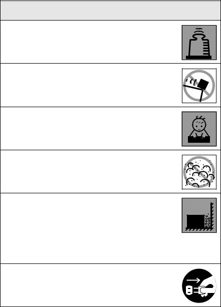
A variety of picture displays have been used in this manual and on the actual product to ensure that the projector is used correctly and safely in order to prevent risks to users and other people, and to prevent damage to property. Explanations for these displays are provided below. Ensure that they are fully understood before reading this manual.
 Warning
 Caution
Displays details that may result in death or injury if ignored.
Displays details that may result in injury or damage to property if ignored.
Point: Includes supplementary explanations and useful tips. See page: Indicates reference pages
*: Refer to the terminology
*Usage of the terms“this unit” and “this projector” in this manual
The terms “this unit” and “this projector” appear regularly in this manual, and these terms also cover the accessories supplied with the projector and other optional products. *The projection distances, illustrations and screen sizes apply to when the standard lens is in use.
Using this manual - 7

■ Safety Precautions
Read and observe the following safety precautions to ensure safe use of the equipment.
 Warning
●If any of the following abnormalities occur, switch off the power supply immediately, remove the plug from the power socket and contact your dealer or nearest address provided at page 107.
·The emission of smoke, strange odours or strange noises.
·Faults, such as images not being able to be projected or no sound being emitted.
·When water or foreign objects have entered the inside of the unit.
·When the unit has been dropped or the case damaged. Continuation of operations under these conditions may result in the outbreak of fire or electric shocks.
Repairs should never be attempted by the user.
Abnormi oder |
Abnormi noise |
●The cabinet to the unit should never be opened by anyone other than our service personnel.
The inside of the projector contains many high-voltage parts that may result in the outbreak of fire, electric shocks or other incidents.
●Never use an electrical voltage other than that displayed.
The use of a voltage other than that specified may result in the outbreak of fire or electric shocks.
Other than |
those specified |
●Verify the specifications of the Power Cord.
The Power Cord supplied with the projector conforms to the electrical specifications of the country of purchase. If the projector is to be used in any other location, check the electrical voltage and shape of sockets in the relevant country beforehand and purchase a cable that conforms to that country’s specifications.
●Never use damaged Power Cord.
Failure to observe this may result in the outbreak of fire or electric shocks.
Also ensure that the following points are strictly observed.
·Never make any modifications to the Power Cord.
·Never place anything heavy on the Power Cord.
·Never bend, twist or pull the cable.
·Ensure that the cable is not installed near heaters.
Contact your dealer or nearest address provided at page 107 if the power cord becomes damaged.
8 - Safety Precautions
 Warning
●Never look into the lens when the power is switched on.
An extremely strong light is emitted that may cause sight defects. Special attention must be paid by households with children.
●Take care when handling power plugs and power connectors.
Failure to observe these instructions may result in the outbreak of fire or electric shocks.
Observe the following precautions when handling power plugs and power connectors.
·Never connect too many appliances to a single socket.
·Never use plugs or connectors to which dust, dirt or other foreign objects have adhered.
·Ensure that the plugs and connectors are firmly inserted as far as they will go.
·Do not attempt to plug in plugs or connectors with wet hands.
·Do not pull the Power Cord when disconnecting plugs and connectors. Always ensure that the actual plug or connector is firmly gripped.
●The projector includes many glass parts, such as the lens and lamps.
If any of these parts should break, handle them with extreme care to avoid injury and then contact your dealer or nearest address provided at page 107 and request repairs.
●Never place vases or containers that contain liquid on top of the projector.
If the water is spilt and enters the outer case, it may result in the outbreak of fire or electric shocks.
●Never insert or drop metal or inflammable objects, or any other
foreign objects into the suction inlets and ventilation outlets on the projector.
Failure to observe this may result in the outbreak of fire or electric shocks.
●Never place the projector or the battery-operated remote control in locations with excessive temperatures, such as in vehicles with closed windows, in areas subject to direct sunlight, or near the fan outlets of air-conditioners and heaters.
Failure to observe this may result in heat-distortion that would have an adverse affect on the contents of the projector, and may result in the outbreak of fire or electric shocks.
Safety Precautions - 9
 Caution
●Never stand on the projector or place any heavy objects on it.
Failure to observe this may result in it dropping over, becoming damaged, or causing injury.
●Never place the projector on unstable surfaces, such as wobbly tables or slanted surfaces.
Failure to observe this may result in it dropping over, becoming damaged, or causing injury.
●Do not place or store the projector within the reach of children’s hands.
Failure to observe this may result in it dropping over, becoming damaged, or causing injury.
●Do not place the projector in humid or dusty locations, or in locations where it would be subject to oil steam or water steam, such as kitchens or near humidifiers.
Failure to observe this may result in the outbreak of fire or electric shocks.
●Never block the projector’s suction inlets or ventilation outlets. Failure to observe this may result in the build up of high temperatures inside the projector, leading to the outbreak of fire. Do not place the projector in the following locations.
·In narrow, badly ventilated areas, such as in cupboards or in bookcases.
·On top of carpets, matresses or blankets.
·Never cover the projectors with table cloth or other material.
Also, if placing by a wall, ensure that at least 20cm of space has been provided between the projector and the wall.
●Always ensure that the plug has been disconnented from the power socket when it is not to be used.
Failure to observe this may result in the outbreak of fire.
10 - Safety Precautions
 Caution
●Always ensure that the power has been switched off, the plug has been disconnected from the power socket, and all other cables have been disconnected when moving the projector.
Failure to observe this may result in the outbreak of fire or electric shocks.
●Never attempt to remove the lamp immediately after the projector has been used. Wait for the projector to cool down suffi-
ciently by leaving it for at least sixty minutes after the power supply has been switched off before attempting this.
Failure to observe this may result in burns or other injuries.
● Misuse of the batteries may result in damage to the batteries |
|
|
and subsequent leakages, leading to the outbreak of fire, injury |
|
|
and product corosion. Observe the following precautions to |
Confirmation |
|
ensure safety. |
||
|
· Never use combinations of different batteries, or old batteries together with new batteries.
·Never use batteries that are not specified in the instruction manual.
·If liquid should leak from the battery, wipe up the leakage with a cloth and then replace the battery accordingly.
·Replace the batteries immediately when the time for replacement arrives.
·Remove the batteries when the projector is not to be used for a long period of time.
·Never apply heat to the batteries, or place them in naked flames or water.
·Ensure that the batteries are inserted in accordance with the correct polarity (+ and -).
·If any liquid that has leaked from a battery gets onto the hands, wash it off immediately with water.
Batteries must be disposed of in accordance with the regulations in effect in each relevant area.
●Ensure that the electric plug and connectors have been disconnected from their sockets when performing maintenance tasks.
Failure to observe this may result in electric shocks.
Safety Precautions - 11

Safety Precautions
●Using the projector outside of the permissible temperature range (+5C° to 40C°) may result in unstable display and excessive loads being placed on the fan, leading to damage to the equipment.
●Storing the projector outside of the permissible temperature range (-10C° to 60C°) may result in damage of the case. Take special care to avoid placing the equipment in direct sunlight for a long period of time.
●Do not use the projector with the lens cover still in place. The heat generated by the lens may cause the cover to become malformed.
●The liquid crystal display panel has been manufactured with high-accuracy technology and contains more than 99.99% active pixels. However, note that there is a possibility of 0.01% of missing pixels and pixels that will be constantly illuminated.
12 - Safety Precautions

Before using this equipment
This section provides explanations on parts and part names, and the items that should be verified before operating the remote control.
■ Parts, Names and Operations
Projector
● Front Panel
2 1
7 |
8 |
9 |
3 |
|
4 |
10 |
6 |
|
5 |
11 |
|
|
|
13 |
6 |
14 |
14 12
1 Operation Indicator
2 Lamp Indicator
3 Temperature Indicator
4Handle
5Lens Shift Knob
6Foot Adjust Lever
7Operation Panel
8Speaker
9Remote Control Receiver
10 Theft-Protection Lock (see page 102) 11 Focus Ring
12 Zoom Ring
13 Lens Cover
14 Front Foot
Parts, Names and Operations - 13
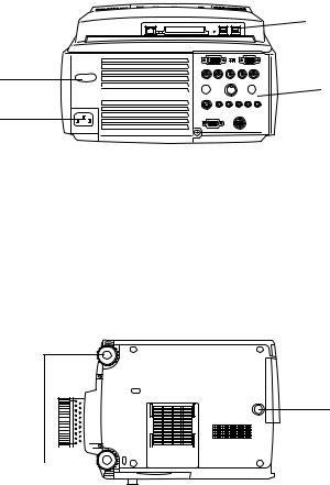
● Back Panel
5
1


 4 2
4 2 

3
1 Remote Control Receiver
2Fan
3Power Inlet
4I/O Port
5EasyMP.net Board
●Rear Panel
2


 3 1
3 1 

1 Front Foot
2 Rear Foot
3 Air Filter (suction inlet)
14 - Parts, Names and Operations
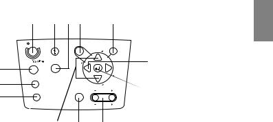
● Operation Panel
4 |
1 |
2 |
3 |
10 |
Power |
Help |
Menu |
|
|
|
Comp/ |
Video |
|
5 |
|
g |
|
n |
|
|
a |
|
|
|
i |
|
|
k |
|
|
c |
|
|
r |
|
|
T |
A/V mute |
|
|
6 |
|
|
Resize |
|
|
7 |
|
|
|
|
Shift |
8 9
Esc
Sync.
T |
11 |
r |
|
a |
|
c |
|
k |
|
i |
|
n |
|
g |
|
Sync. |
12 |
Keystone |
Volume
13
1 [Help] button (see page 53)
Displays the methods of solving problems. Press this button when trouble occurs.
2 [Video] button (see page 43)
Switches the images between video images (Video), S video (S-Video) and component video (BNC (YCbCr)).
3 [Menu] button (see page 66)
Displays and cancels the menu.
4 [Power] button (see page 42, 45 )
Switches the power supply on and off.
5 [Comp/EasyMP.net] button (see page 43)
Switches the Computer #1 images, BNC (RGB) and the EasyMP.net images.
6 [A/V mute] button (see page 55)
Temporarily erases the image and sound. Projection is resumed when this button is pressed once more or when the volume control is adjusted or when the menu is displayed. User logos can also be set up for projection when in the A/V mute mode.
7 [Resize] button (see page 56)
Switches between the window display and the resizing display when computer images are being projected. Switches the aspect ratio between 4:3 and 16:9 when video images are being projected.
8 [Sync] button (see page 51)
Makes the necessary adjustments when the screen is out of focus or flickering. This button functions as the up and down key when the menu or help text are being displayed.
9 [Shift] button (see page 63)
Adjusts the volume when pressed simultaneously with the [Volume (Keystone)] button.
10 [ESC] button (see page 67)
Ends functions that are currently in use. Returns the screen to the previous stage when this is pressed during menu and help text display.
11 [Tracking] button (see page 51)
Performs the necessary adjustments when stripes appear on the screen. Moves left and right when this is pressed during menu and help text display.
12 [
 (Enter)] button (see page 50, 66)
·Sets the menu item and moves onto the lower stage.
·Optimizes the computer image when the menu or help text are not displayed. (Switches the input resolution across to [Auto] when set for [Manual]).
13 [Keystone] button (see page 49)
Performs the necessary adjustments when the screen distorts into a trapezoid shape.
Parts, Names and Operations - 15

● I/O Ports
|
|
|
3 |
2 |
|
1 |
|
|
|
|
|
|
Computer 1 |
|
|
|
|
|
|
|
Computer 2 /Component Video |
|
|
|
||
|
|
R/Cr/Pr |
G/Y |
B/Cb/Pb |
H/C Sync |
V Sync |
4 |
|
|
|
|
||||||
5 |
|
|
|
|
|
|
|
7 |
6 |
10 |
Remote |
|
Mouse/Com |
|
Audio |
11 |
|
|
|
|
|
|
||||
|
8 |
|
|
|
|
|
|
9 |
|
|
S-Video |
S-Audio/Audio2 |
Video |
L-Audio-R |
|||
|
|
|
||||||
12


 13
13
Monitor Out |
Stack Out |
1 Computer 1 mini D-Sub 15 Port
Inputs the computer’s analog image signals.
2 Change-over Switch
Switches the valid port for Computer #1 across to either mini D-Sub15 (analog) or DVI-D (digital). Operate the switch with the tip of a ballpoint pen or other pointed object.
3 Computer 1 DVI-D Port
Inputs the computer’s digital image signals.
4 Computer 2/Component Video-BNC Port
· R/Cr/Pr · G/Y · B/Cb/Pb · H/C Sync · V Sync
Inputs the computer’s BNC image signals, the A/V equipment component image signals (color differential signal*) or the RGB image signals.
5 Remote Port
Connects the optional remote control receiver (ELPST04).
6 Mouse/Com Port
Establishes a connection with the computer when the EasyMP.net Software that is supplied is to be used when the remote control is used as a wireless mouse.
7 Audio Port
Inputs the audio signals from the computer and A/V equipment connected to the Computer #1 Port.
8 S-Video Port
Inputs the A/V equipment's S image signals.
9 S-Video/Audio 2 Port
Inputs the audio signals from the computer and A/V equipment connected to the BNC port or the S-Video port.
Outputs only the sound for connected computers and A/V equipment.
10 Video Port
Inputs the the A/V equipment’s component image signals.
11 L-Audio-R Port
Inputs the the A/V equipment’s sound signals.
12 Monitor Out Port
Outputs the projected image signals to an external monitor (not output when the input comes from the DVI-D port).
13 Stack Out Port
This is used during stack projection.
16 - Parts, Names and Operations

● EasyMP.net board
|
|
LAN |
|
|
|
|
|
Card Slot |
|
|
|
|
|
|
USB |
|
|||||||||||
|
|
|
|
|
|
|
|
|
|
|
|
|
|
|
|
|
|
|
|
|
|
|
|
|
|
|
|
|
|
|
|
|
|
|
|
|
|
|
|
|
|
|
|
|
|
|
|
|
|
|
|
|
|
|
|
|
|
|
|
|
|
|
|
|
|
|
|
|
|
|
|
|
|
|
|
|
|
|
|
|
|
|
|
|
|
|
|
|
|
|
|
|
|
|
|
|
|
|
|
|
|
|
|
|
|
|
|
|
|
|
|
|
|
|
|
|
|
|
|
|
|
|
|
|
|
|
|
|
|
|
|
|
|
|
|
|
|
|
|
1 |
2 |
3 |
1. Network Connector
Connects the projector to a network.
2. PCMCIA Card Slot
For the insertion of memory cards.
3. USB Port
Used for connecting the USB mouse, USB keyboards and USB tablets, etc.
Point
Refer to the “EasyMP.net User’s Guide” for details on the EasyMP.net functions.
Parts, Names and Operations - 17

Remote Control
● Front Panel
1
2
3
4
5
6
7
Power
Freeze |
|
8 |
A/V Mute |
|
|
E-Zoom |
R/C ON |
9 |
OFF |
|
3 |
2 |
4 |
1 |
5 |
|
Enter |
Esc
10
11
1 Remote control light-receiving area
Outputs the remote control unit’s signals.
2 Indicator
Illuminated when the remote control unit signals are being output.
Light will not be emitted when the batteries are getting low or when the [R/C ON OFF] switch is set at [OFF].
3 [Freeze] button (see page 55)
Temporarily freezes the image. Press this button once more to cancel the freeze mode.
4 [A/V Mute] button (see page 55)
Temporarily mutes the images and sound. To resume projection, press the button once more, adjust the volume control, or display the menu.
It is also possible to project the user logo when the A/V mute function is operating.
5 [E-Zoom] button (see page 58, 62)
Enlarges and reduces the size of the image. The image in the sub-screen will be enlarged when Picture-in-Picture images are being projected. Press the [Esc] button to cancel this function.
6 [Effect] button (see page 59)
Executes the allocated effect function. Press the [ESC] key to cancel this mode.
7 [ (Light)] button
The remote control button will be illuminated for approximately ten seconds.
8 [Power] button (see page 42, 45)
Switches the power supply to the projector on and off.
9 [R/C ON OFF] switch (see page 42, 46)
Switches the remote control unit on and off. The remote control unit cannot be used for operations when this switch is not set at [ON].
18 - Parts, Names and Operations
10 [Enter] button (see page 36, 66)
·Sets the menu item when pressed, and then moves onto the lower stage. Becomes a cursor key to select the menu items when moved up, down, left or right.
·This function operates with a left-hand click on the mouse when computer images are being projected. The pointer will move when this button is moved up, down, left or right.
11 [ESC] button (see page 36, 67)
·Ends the function being used. Returns to the previous stage when the menu or help text is being displayed.
·This function operations with a right-hand click on the mouse when computer images are being projected.
●Inside of the Cover
|
Esc |
Menu |
Help |
1 |
8 |
Comp1 |
Comp2/YCbCr |
2 |
9 |
|
Video |
4 |
3 |
Capture |
APPs |
Auto |
Resize |
5 |
10 |
P in P |
Preset |
6 |
11 |
- Volume +
7
1 [Menu] button (see page 66)
Displays and ends the menu.
2 [Comp1] button (see page 43)
Switches across to the image from computer #1 port. (Switches across to the DVI-D image when the switch is set to the Digital (left-hand side)).
3 [Video] button (see page 43)
Switches between video images (Video) and S-video images (S-Video).
4[EasyMP.net] button (see page 43)
Switches across to EasyMP.net images.
5[Auto] button (see page 50)
Optimizes the computer images. The projected image will be captured when EasyMP.net images are being projected.
6 [P in P] button (see page 62)
Displays the video image within the computer image or the video image as a sub-screen. This function is cancelled by pressing this button once again.
7 [Volume] button (see page 63)
Adjusts the volume.
8 [Help] button (see page 53)
Displays the method of solving problems. Press this button when trouble occurs.
9 [Comp2/YCbCr] button (see page 43)
Switches between the images from the BNC port.
Parts, Names and Operations - 19
10 [Resize] button (see page 56)
Switches between the window display and the resizing display when computer images are being projected. Switches the aspect ratio between 4:3 and 16:9 when video images are being projected.
An application list will be displayed when EasyMP.net images are being projected.
11 [Preset] button (see page 51)
Calls out the preset computer input settings.
● Rear Panel
1
1 Battery Cover
20 - Parts, Names and Operations

Range of Remote Control Operations
Depending on the distance and angle from the main unit’s light receiving area, there are cases where the remote control will not function. Ensure that the remote control is used within the following conditions:
●Operable distance: Approximately 10 metres
●Operable range:
(Front Panel) |
(Rear Panel) |
|||||||||||||||
|
|
|
|
|
|
|
|
|
|
|
|
|
|
|
|
|
|
|
|
|
|
|
|
|
|
|
|
|
|
|
|
|
|
Approximately 30 |
Approximately 30 |
|
degrees to the |
||
degrees to the |
||
left and right |
||
left and right |
||
|
Approximately 15 |
|
|
Approximately 15 |
|||
degrees up and down |
|
|
degrees up and down |
|||
|
|
|
|
|
|
|
|
|
|
|
|
|
|
|
|
|
|
|
|
|
|
|
|
|
|
|
|
Approximately 15 |
Approximately 15 |
degrees |
degrees |
Point
·Ensure that the R/C ON OFF switch is set at [ON] when using the remote control unit.
·Aim the remote control at the projector’s light-receiving area.
·There are cases where the operable distance (approximately 10 meters) of the remote control is diminished when signals are reflected off screens depending on the type of screen in use.
·Ensure that sunlight and florescent lighting is not shone directly into the projector’s lightreceiving area.
·If the remote control will not function or malfunctions, there is a possibility that the batteries need changing. In this event, replace the batteries accordingly.
·Use the optional remote control receiver (ELPST04) if it is to be used at a distance of 10m or more.
Parts, Names and Operations - 21

Inserting the Remote Control Batteries
The remote control batteries are inserted in accordance with the following procedure:
 Caution
Ensure that unused batteries of the same type are used.
1 Remove the Battery Cover.
Apply pressure to the clip holding the Battery Cover, and then lift it upwards.
2 Insert the batteries.
Ensure that the batteries are aligned correctly with the “+” and “-“ labels on the remote control.
3 Replace the cover.
Apply pressure to the battery cover until it clicks firmly into place.
Point
·Specified batteries: Two three-cell alkaline manganese batteries (LR6).
·The batteries should be replaced approximately once every three months when used for thirty minutes per day.
22 - Parts, Names and Operations

Installation
This section provides an example of projector installation, and explanations on the projection distances and projection angles.
■ Installation Procedure
Determines the projection angle and projection distance to ensure the most suitable screen display.
 Caution
·Do not block the ventilation outlet at the back of the projector or the Air Filter (suction inlet) on the rear panel.
·There are cases where material or paper get sucked onto the Air Filter on the rear panel when the projector is in use, so attention must be paid to prevent this.
·Do not place the projector in a location where it is subject to the direct air flow from air conditioners or heaters.
·When the projector is to be placed near a wall, ensure that there is at least 20cm of space between the wall and the projector.
·Do not cover the projector with table cloths or other material.
Installation example
The projector may be installed in locations that conform to the installation conditions and projection methods.
Viewing projected images from the front
Installation Procedure - 23
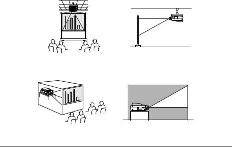
Viewing projected images from the front with a ceiling suspended projector
Use the optional ceiling suspension unit and set the ceiling suspension parameter to [ON]. (see page 72)
Viewing images projected onto half-transparent screens from the rear.
·Set the rear parameter to [ON]. (see page 72)
·Ceiling suspension is also possible with the use of the optional ceiling suspension unit.
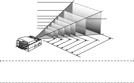
Screen size and projection distance
Determines the distance that the screen must be from the lens in order to obtain the required screen size.
The projector’s Standard Lens is approximately a 1.4x zoom lens and the largest screen size is about 1.4 times the size of the smallest screen.
Using the following table for reference purposes, install the projector so that the screen size is smaller than the screen.
24 - Installation Procedure
Screen Size |
Approximate Projection Distance |
|
|
|
|
|
|
|
|
30-inch (61×46cm) |
1.1m |
to 1.4m |
|
|
|
|
|
|
|
40-inch (81×61cm) |
1.5m |
to 1.8m |
|
|
|
|
|||
|
|
|
|
|
60-inch (120×90cm) |
2.3m |
to 2.8m |
|
|
|
|
|
|
|
80-inch (160×120cm) |
3.0m |
to 3.8m |
|
|
|
|
|
|
|
100-inch (200×150cm) |
3.8m |
to 4.8m |
|
|
|
|
|
|
|
200-inch (410×300cm) |
7.6m |
to 9.7m |
|
|
|
|
|
|
|
300-inch (610×460cm) |
11.4m to 14.6m |
|
|
|
|
|
|
|
|
Screen Size
300-inch
200-inch
100-inch
80-inch
60-inch
40-inch
30-inch
610X460 |
cm |
|
|
|
|
|
|
410X300 |
cm |
|
|
|
|
|
|
|
|
|
|
200X150 |
cm |
|
|
|
|
160X120 |
|
|
||
|
|
cm |
|
|
||
|
|
120X90 |
|
|
|
|
81X61 |
cm |
|
|
|
||
|
|
|
|
|||
cm |
|
|
|
|
||
61X46 |
cm |
|
|
|
|
|
|
|
|
|
|
||
|
|
|
|
|
|
|
Center of the lens
.4 |
|
|
|
|
|
|
|
|
1 |
|
.8 |
|
|
|
|
|
|
- |
|
|
|
|
|
|
|
|
.1 |
|
1 |
.8 |
|
|
|
|
|
1 |
|
- |
|
|
|
|
||
|
.5 |
2 |
|
.8 |
|
|
|
|
|
1 |
|
- |
|
|
|
|
|
|
|
.3 |
|
3 |
.8 |
|
|
|
|
|
2 |
|
|
- |
|
|
|
|
|
|
|
.0 |
4 |
.7 |
|
|
|
|
|
|
3 |
3 |
- |
6m |
|
|
|
|
|
|
|
- |
||
|
|
|
|
|
.8 |
9 |
. |
|
|
|
|
|
|
|
|
.6 |
-14 |
|
|
|
|
|
|
|
7 |
.4 |
|
|
|
|
|
|
|
|
1 |
Distance from the projector
Point
·The projection distances listed above are the distances when the standard lens is in use. If optional lenses are to be used, refer to the relevant instruction manuals for further details.
·The screen size will become smaller when the trapezoid correction function is used.
Installation Procedure - 25
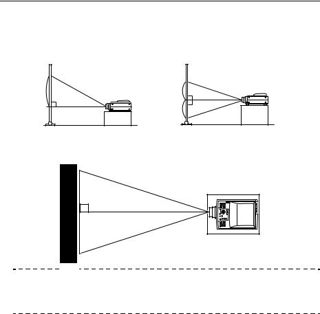
Projection angles
The optimum projection screen is acquired by placing the center of the projector ’s lens and a right-angle to the screen.
When viewing from the side
It is possible to move the projection position up and down with the lens shift function
A |
A |
B |
B |
A:B 10:Becomes 0 |
A:B 5:Becomes 5 |
When viewing from the top or bottom
Point
Although the projection position can be adjusted with the foot lever (see page 47), there are cases where the screen will distort into a trapezoid shape. In this event, adjust the trapezoid distortion with the trapezoid correction function. (see page 49)
26 - Installation Procedure

Connections
This section provides explanations on connecting the projector to computers and video equipment.
■ Connecting the projector to a computer
Switch off the power supply to the projector and computer before attempting to make the connection.
Eligible computers
There are computers with which connections cannot be established and computers that cannot be used for projection purposes even though a connection has been established. First of all, it is necessary to confirm that a connection can be established with the computer in use.
● Conditions for eligible computers
Condition #1: The computer must be fitted with an image signal output port
Check to ascertain that the computer is fitted with ports that will output image signals, such as the [RGB Port], the [Monitor Port] and the [Video Port]. If you have trouble confirming this, refer to chapter on external monitor connections in the computer ’s instruction manual.
There are computers, such as combined computer/monitor models and laptop models, that do not allow connections or for which optional external output ports must be purchased.
Point
Depending on the computer, there are cases when it is necessary to switch the image signal output with the connection key ( , etc.,) and the settings.
NEC |
Panasonic |
Toshiba |
IBM |
SONY |
FUJITSU |
Macintosh |
Fn+F3 |
Fn+F3 |
Fn+F5 |
Fn+F7 |
Fn+F7 |
Fn+F10 |
Mirroring is set up with monitor |
|
|
|
|
|
|
adjustments on the control panel after |
|
|
|
|
|
|
starting up. |
|
|
|
|
|
|
|
The table shown above provides examples for certain products. Refer to the computer’s instruction manual for further details.
Condition #2: The resolution and frequency of the computer must be within the boundaries listed in the chart on the next page.
Projection will not be possible if the computer does not support the output image signal resolutions and frequencies shown in the chart on the next page (there are cases where projection is possible, but vivid projection will not be possible).
Confirm the image signal resolution and frequency with the computer’s instruction manual.
There are also computers available that allow the output resolution to be amended. In this case, amend the parameters to fit within the ranges shown in the chart on the next page.
Connecting the projector to a computer - 27
Signal |
Refresh Rate |
Resolution |
Pixels (dots) |
Pixels (dots) |
Remarks |
|
(Hz) |
(Dots) |
Used During |
Used During |
|
|
|
|
Resizing Dis- |
Real Display |
|
|
|
|
play (Resize |
(Resize Off) |
|
|
|
|
On) |
|
|
PC98 |
|
640×400 |
1024×640 |
640×400 |
|
|
|
|
|
|
|
VGACGA |
|
640×400 |
1024×640 |
640× 400 |
|
|
|
|
|
|
|
VGAEGA |
|
640× 350 |
1024×560 |
640×350 |
|
|
|
|
|
|
|
VGA |
60 |
640× 480 |
1024×768 |
640× 480 |
|
|
|
|
|
|
|
VESA |
72/75/85/ |
640×480 |
1024×768 |
640×480 |
|
|
100/120 |
|
|
|
|
|
|
|
|
|
|
SVGA |
56/60/72/75/ |
800×600 |
1024×768 |
800×600 |
|
|
85/100/120 |
|
|
|
|
|
|
|
|
|
|
XGA |
43i/60/70/75/ |
1024×768 |
1024×768 |
1024× 768 |
|
|
85/100 |
|
|
|
|
|
|
|
|
|
|
SXGA |
70/75/85 |
1152×864 |
1024×768 |
1152× 864 |
Virtual (Partial) Display |
|
|
|
|
|
|
SXGA |
60/75/85 |
1280× 960 |
1024×768 |
1280×960 |
Virtual (Partial) Display |
|
|
|
|
|
|
SXGA |
43i/60/75/85 |
1280×1024 |
960×768 |
1280×1024 |
Virtual (Partial) Display |
|
|
|
|
|
|
SXGA+ |
|
1400×1050 |
1024×768 |
1400×1050 |
Virtual (Partial) Display |
|
|
|
|
|
|
|
|
1440×1080 |
1024×768 |
1440×1080 |
|
|
|
|
|
|
|
UXGA |
48i/60/65/70/ |
1600×1200 |
1024×768 |
1600×1200 |
Virtual (Partial) Display |
|
75/80/85 |
|
|
|
|
|
|
|
|
|
|
MAC13 |
|
640× 480 |
1024×768 |
640×480 |
|
MAC16 |
|
832×624 |
1024×768 |
832×624 |
|
MAC19 |
|
1024×768 |
1024×768 |
1024×768 |
|
MAC21 |
|
1152×870 |
1016×768 |
1152×870 |
Virtual (Partial) Display |
|
|
640×480 |
1024×768 |
640×480 |
|
iMAC |
|
800×600 |
1024×768 |
800×600 |
|
|
|
1024×768 |
1024×768 |
1024×768 |
|
NTSC |
|
|
1024×768 |
1024×576 |
4:3 ↔ 16:9, Selectable |
PAL |
|
|
1024×768 |
1024×576 |
4:3 ↔ 16:9, Selectable |
SECAM |
|
|
1024×768 |
1024×576 |
4:3 ↔ 16:9, Selectable |
SDTV |
60 |
|
1024×768 |
1024×576 |
|
(480P/i) |
|
|
|
|
|
|
|
|
|
|
|
HDTV |
60 |
|
1280×720 |
1024×576 |
|
(720P) |
|
|
|
(16 : 9) |
|
|
|
|
|
|
|
HDTV |
60 |
|
1024×768 |
1024×576 |
|
(1080P/i) |
|
|
|
(16 : 9) |
|
|
|
|
|
|
|
28 - Connecting the projector to a computer
 Loading...