


D-Link DKVM-IP1
1 Port KVM Switch
Over IP
Manual
Version 1.00

CONTENTS
1 THE QUICK INSTALLATION GUIDE |
1 |
|||
2 |
INTRODUCTION |
4 |
||
|
2.1 |
When the sever is up and running |
4 |
|
|
2.2 |
When the server is dead |
4 |
|
|
2.3 |
Features |
|
5 |
|
2.4 |
Package contents |
5 |
|
|
2.5 |
Technical specifications |
6 |
|
|
2.6 |
System requirement |
6 |
|
|
2.7 |
Cable diagrams |
7 |
|
|
2.8 |
LED Indicators |
7 |
|
3 |
HARDWARE INSTALLATION |
8 |
||
|
3.1 |
Operation overview |
8 |
|
|
3.2 |
Connecting DKVM-IP1 to the host system |
8 |
|
|
3.3 |
Connecting DKVM-IP1 to multi-port KVM switch |
11 |
|
4 |
CONFIGURATION |
12 |
||
|
4.1 |
Initial Configuration |
12 |
|
|
|
4.1.1 Initial configuration via DHCP server |
12 |
|
|
|
4.1.2 Initial configuration via serial console |
13 |
|
|
|
4.1.3 Keyboard, Mouse and Video configuration |
14 |
|
|
|
4.1.3.1 DKVM-IP1 switch keyboard settings |
14 |
|
|
|
4.1.3.2 |
Remote Mouse Settings |
15 |
|
|
4.1.3.3 Auto mouse speed and mouse synchronization |
15 |
|
|
|
4.1.3.4 Host system mouse settings |
15 |
|
|
|
4.1.3.5 Single and Double Mouse Mode |
16 |
|
|
|
4.1.3.6 |
Recommended Mouse Settings |
16 |
|
|
4.1.3.7 |
Video Modes |
16 |
5 |
USAGE |
|
17 |
|
|
5.1 |
Prerequisites |
17 |
|
|
5.2 |
Login into the DKVM-IP1 switch and logout |
18 |
|
|
|
5.2.1 Login into the DKVM-IP1 switch |
18 |
|
|
|
5.2.2 Logout from the DKVM-IP1 switch |
20 |
|
|
5.3 |
The Remote Console |
20 |
|
|
5.4 |
Main Window |
20 |
|
|
|
5.4.1 Remote Console Control Bar |
21 |
|
|
|
5.4.2 Remote Console Status Line |
28 |
|

6 |
MENU OPTIONS |
29 |
|
|
6.1 Remote |
|
29 |
|
6.1.1 |
KVM Console |
29 |
|
6.1.2 |
Telnet Console |
29 |
|
6.2 Mapping |
31 |
|
|
6.2.1 |
Floppy Disk |
31 |
|
6.2.2 |
CD ROM |
32 |
|
6.2.3 |
Drive redirection |
36 |
|
6.2.4 |
Options |
39 |
|
6.3 User |
|
40 |
|
6.3.1 |
Change Password |
40 |
|
6.3.2 |
Users |
40 |
|
6.4 Setting |
|
41 |
|
6.4.1 |
User Console |
41 |
|
6.4.2 |
Keyboard/Mouse |
44 |
|
6.4.3 |
Video |
45 |
|
6.5 Network |
46 |
|
|
6.5.1 |
Network |
46 |
|
6.5.2 |
Dynamic DNS |
48 |
|
6.5.3 |
Security |
50 |
|
6.5.4 |
Certificate |
51 |
|
6.5.5 |
Serial Port |
53 |
|
6.5.6 |
Date And Time |
55 |
|
6.5.7 |
Event Log |
56 |
|
6.6 Tools |
|
58 |
|
6.6.1 |
Device Status |
58 |
|
6.6.2 |
Event Log |
59 |
|
6.6.3 |
Update Firmware |
60 |
|
6.6.4 |
Unit Reset |
61 |
7 |
TROUBLESHOOTING |
62 |
|
8 |
CERTIFICATES |
63 |
|
A.Pin Assignments
B.Key Codes
C.Video Modes
D.Rack mount kit installation diagram
1. The quick installation guide
Installation
DKVM-IP1 switch redirects local keyboard, mouse and video data to a remote administration console. All data is transmitted via IP. DKVM-IP1 switch can be used in a multi administrator and multi server environment as well. Besides, DKVM-IP1 switch is a KVM switch, which can also be used with a local console.
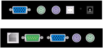
DKVM-IP1 switch hardware installation
Host
Console
Figure 1-1 The connectors of single port DKVM-IP1 switch front and rear side
Please perform the following steps:
1.Connect the power supply to DKVM-IP1 switch
2.Connect the monitor to the DKVM-IP1 switch console side.
3.Connect the keyboard to the DKVM-IP1 switch console side.
4.Connect the mouse to the DKVM-IP1 switch console side.
5.Connect a VGA cable (15-pin HDDB Male / Male) with the Male side to both of the PC and the host port of the DKVM-IP1 switch.
6.Connect one purple end of 3-in-one cable to the PS/2 mouse port on the computer, and the other end of 3-in-one cable to the host PS/2 mouse port on the DKVM-IP1 Switch.
7.Connect one green end of 3-in-one cable to PS/2 keyboard port on the computer, and the other end of 3-in-one cable to the host PS/2 keyboard port on the DKVM-IP1 switch.
8.Connect the type A connector of USB A-B cable to the host system, while using remote mass storage control.
9.Connect Ethernet to LAN port and/or modem to DB-9 serial port, depending on how you want to access DKVM-IP1 switch
Video modes
DKVM-IP1 switch recognizes a limited number of common video modes. When running X-Window on the host system, please don’t use any custom mode lines with special video modes. If done so, DKVM-IP1 switch may not be able to detect these. You are on the safe side with all standard VESA video modes. Please refer to Appendix C for a list of all known modes.
1
Initial IP configuration
Initially the DKVM-IP1 switch network interface is configured with the parameters shown in Table 1-1.
Parameter |
Value |
IP auto configuration |
DHCP |
IP-Address |
192.168.0.70 |
Net-mask |
255.255.255.0 |
Default-Gateway |
none |
Table 1-1: Initial configuration
If this initial configuration doesn’t meet your local requirements, you need to do the initial IP configuration. Use one of the following ways:
1. Connect the enclosed NULL modem cable to the serial interface on the rear side. The serial interface needs to be adjusted with the parameters shown in table 1-2:
Parameter |
Value |
Bits/second |
115200 |
Data bits |
8 |
Parity |
No |
Stop bits |
1 |
Flow Control |
None |
Table 1-2: Serial parameters
Use a terminal software (e.g. hyper term or minicom) to connect to DKVM-IP1 switch. Reset
DKVM-IP1 switch and immediately press < ESC >. You will see some device information and a ’=>’ prompt. Enter the command ’config’ and press < Enter >. After waiting a few moments you may configure IP auto configuration, IP address, net mask and default gateway. Pressing < Enter > without entering values does not change settings. The gateway value must be set to 0.0.0.0 (for no gateway) or any other value. You will be asked if the values are correct and get a chance to correct them. After confirming, DKVM-IP1 switch performs a reset.
2. Use a crossover Ethernet cable to connect DKVM-IP1 switch to a subnet where a DHCP server is available. After the DHCP server has assigned an IP address to DKVM-IP1 switch you can use the web interface to configure the device.
Web interface
DKVM-IP1 switch may be accessed using a standard JAVA enabled web browser. You may use the
HTTP protocol or a secure encrypted connection via HTTPS. Just enter the configured IP address of
DKVM-IP1 switch into your web browser.
Login name |
admin (factory default) |
Password |
admin (factory default) |
2

Changing these settings to user specific values is strongly recommended and can be done on the User Management page (see the Section called
Users and Groups in Chapter 6 ).
Remote Console
The Remote Console is the redirected screen, keyboard and mouse of the remote host system to which DKVM-IP1 switch is installed. The web browser which is used for accessing DKVM-IP1 switch has to supply a Java Runtime Environment version 1.1 or higher. However, it is strongly recommended to install Sun JVM 1.4. The Remote Console will behave exactly the same way as if you were sitting directly in front of the screen of your remote system. That means that both the keyboard and mouse can be used in the usual way. Open the console by selecting the preview picture on the main site of the HTML front end. Figure 1-2 shows the top of the Remote Console.
Figure 1-2: Top part of the Remote Console
There are some options to choose from, and the important ones are the following:
Auto Adjust button 
If the video displayed is of bad quality or distorted in some way, press this button and wait a few seconds while DKVM-IP1 switch tries to adjust itself for the best possible video quality.
Sync Mouse 
Choose this option in order to synchronize the local with the remote mouse cursor. This is especially necessary when using accelerated mouse settings on the host system. In general there is no need to change mouse settings on the host.
Video Settings in Options Menu This opens a new window with elements to control the DKVM-IP1 switch Video Settings. You can change some values, for instance the brightness and contrast of the picture displayed, which may improve the video quality. It is also possible to revert to the default settings for all video modes or only the current one.
Note: At first start, if the local mouse pointer is not synchronized with the remote mouse pointer, press the Auto Adjust Button once.
3
2. Introduction
Thank you for purchasing DKVM-IP1 switch. DKVM-IP1 switch can save your MONEY, TIME, SPACE, EQUIPMENT and POWER. DKVM-IP1 switch defines a new class of remote KVM access devices. DKVM-IP1 switch combines digital remote KVM access via IP networks with comprehensive and integrated system management.
DKVM-IP1 switch provides convenient, remote KVM access and control via LAN or Internet. It captures, digitizes, and compresses video signal and transmits it with keyboard and mouse signals to and from a remote computer. DKVM-IP1 switch provides a non-intrusive solution for remote access and control. Remote access and control software runs on its embedded processors only but not on mission-critical servers, so that there is no interference with server operation or impact on network performance.
Furthermore, DKVM-IP1 switch offers additional remote power management with the help of optional available device.
DKVM-IP1 switch supports consoles consisting of PS/2 style keyboards and mouse and HDDB 15 video output. DKVM-IP1 switch will automatically detect the current video mode of the console, however manual fine-tuning is recommended to receive the best video quality. DKVM-IP1 switch will accept video streams up to 110 MHz dot clock. This results in a screen resolution of 1280x1024 pixels with a frame rate of 60 Hz.
2.1. When the server is up and running
DKVM-IP1 switch gives you a full control over the remote server. The Management Console allows you to access the remote server’s graphics, keyboard and mouse and to send special commands to the server. You can also perform periodic maintenance of the server. Using the Console Redirection Service, you are able to do the following:
I.Reboot the system
II.Watch the boot process.
III. Boot the system from a separate partition to load the diagnostic environment.
IV. Run special diagnostic programs.
2.2. When the server is dead
Obviously, fixing hardware defects is not possible through a remote management device.
Nevertheless DKVM-IP1 switch gives the administrator valuable information about the type of a hardware failure. Serious hardware failures can be categorized into five different categories with different chances to happen:
I.Hard disk failure 50%
II.Power cable detached, power supply failure 28%
III. CPU, Controller, main board failure 10%
IV. CPU fan failure 8%
V.RAM failure 4%
Using DKVM-IP1 switch, administrators can determine which kind of serious hardware failure has occurred (See table 2-1).
4
Type of failure |
Detected by |
Hard disk failure |
Console screen, CMOS set-up information |
Power cable detached, power supply failure |
Server remains in power off state after power on |
|
command has been given. |
CPU Controller, main board failure. |
Power supply is on, but there is no video output. |
CPU fan failure |
By server specific management software |
RAM failure |
Boot-Sequence on boot console |
Table 2-1:Host system failures and how they are detected.
2.3. Features
zManage serves around the world
zKVM (keyboard, video, mouse) access over IP and analogous telephone line (modem needed).
zBIOS level access
zSSL encryption
zNo impact on server or network performance
zAutomatically senses video resolution for best possible screen capture
zHigh-performance mouse tracking and synchronization
zPort to connect a user console for direct analogous access to KVM switch
zLocal Mouse suppression (only when using SUN’s Java Virtual Machine)
zCan be used with any standard KVM
zRemote mass storage control.
2.4.Package contents
DKVM-IP1 1 Port KVM Over IP |
1 PC |
|
|
User’s manual |
1 PC |
|
|
CD-ROM with Manual and software |
1 PC |
|
|
5V 2.5A DC Power Adapter |
1 PC |
|
|
Rack Mount Kit |
1 PC |
|
|
Serial cable |
1 PC |
|
|
USB cable in 6ft |
1 PC |
|
|
3-in-1 KVM cable in 3ft |
1 PC |
|
|
5

2.5. Technical specifications
Model No. |
|
DKVM-IP1 1port KVM Switch Over IP |
|
|
|
PC Port |
1 |
|
|
|
|
Console Port |
1 |
|
|
|
|
PC Port Connector |
|
PS/2 Keyboard Mini Din 6 pin |
(All Female Types) |
|
PS/2 Mouse Mini Din 6 pin |
|
|
VGA HDDB 15 pin |
|
|
USB Type B receptacle |
Console Port Connector
(All Female Types)
Local Console: PS/2 Keyboard Mini Din 6 pin
PS/2 Mouse Mini Din 6 pin VGA HDDB 15pin
Remote Console: RJ-45 8P8C
Serial Port (DB9 pin Male)
LAN port (RJ-45 8P8C)

 1
1
1
10BASE-T Ethernet uses Category 3/4/5/5E/6 UTP 100BASE-T Ethernet uses Category 5/5E/6 UTP
Reset button |
|
1 |
|
|
|
Keyboard Emulation |
|
PS/2 |
|
|
|
Mouse Emulation |
|
PS/2 |
|
|
|
VGA Resolution |
|
Local :1600 X1200 Remote : 1280 X1024 |
|
|
|
Housing |
|
Metal |
|
|
|
Power Adapter |
|
DC 5V, 2.5A |
|
|
|
Operation Temperature |
|
0~50 |
|
|
|
Storage Temperature |
|
-20 ~ 60 |
|
|
|
Humidity |
|
0~80%, Non-Condensing |
|
|
|
Size |
|
Desktop |
|
|
|
Weight (kg) |
|
0.67kg |
|
|
|
Dimension (mm) |
|
156 X139 X27 |
2.6. System requirement
Item
Local console side
Description
One PS/2 Keyboard, one PS/2 Mouse and one monitor
Remote Console side
Computer side
One PC or Multiple PCs are linked into the network
One PC or Server or the console port of KVM switch unit
6
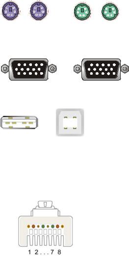
2.7. Cable diagrams PS/2 Cable:
Mini Din 6 pin Male to Male
VGA Cable:
HDB15 pin Male to Male
USB 2.0 Cable:
USB A-B cable
CAT5/5E/6 Straight Through UTP/STP Cable:
8P8C
2.8. LED Indicators:
LED Indicator |
Color |
Status |
Description |
|
|
|
|
|
|
|
Green |
Solid |
Properly connected to the network |
|
|
|
|
||
Link/speed |
Blinking |
Sending or Receiving Data |
||
|
||||
|
|
|
||
Orange |
Solid |
Connect to 100 Mbps network |
||
|
||||
|
|
|
||
|
Light off |
Connect to 10 Mbps network |
||
|
|
|||
|
|
|
|
7
3.Hardware installation
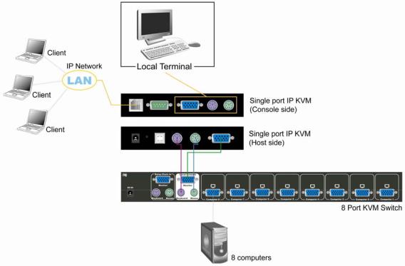
3.1Operation Overview
Figure 3-1 shows the connections of DKVM-IP1 switch to its host, to peripheral devices, to the power source and to the local area network.
DKVM-IP1
KVM Cable
IP Network |
PC/Servers |
Administrator
Figure 3-1.a: DKVM-IP1 switch usage scenario
DKVM-IP1
KVM Cable
|
8/16 PS/2 |
IP Network |
KVM Switch |
PC/Servers
Administrator
Figure 3-1.b: DKVM-IP1 switch usage scenario
DKVM-IP1 switch redirects local keyboard, mouse, and video data to a remote administration console. All data is transmitted with the TCP/IP protocol family.
DKVM-IP1 switch can be used in a multi administrator and multi server environment as well. Attaching one or several DKVM-IP1 switches to a KVM switch matrix allows accessing multiple servers on a single remote console.
3.2 Connecting DKVM-IP1 switch to the host system
In order to connect the DKVM-IP1 switch of the host system performs the following steps:
Step 1
Connect the power supply on DKVM-IP1 switch
8

Step 2
Connect the monitor to the DKVM-IP1 switch console side.
Step 3
Connect the keyboard to the DKVM-IP1 switch console side.
Step 4
Connect the mouse to the DKVM-IP1 switch console side.
Step 5
Connect a VGA cable (15-pin HDDB Male / Male) with the Male side to both of the PC and the host of the DKVM-IP1 switch.
Step 6
Connect one end to the PS/2 mouse port on the computer, and the other end to the host PS/2 mouse port on the DKVM-IP1 switch.
Step 7
Connect one end to PS/2 keyboard port on the computer, and the other end to the host PS/2 keyboard port on the DKVM-IP1 switch.
9
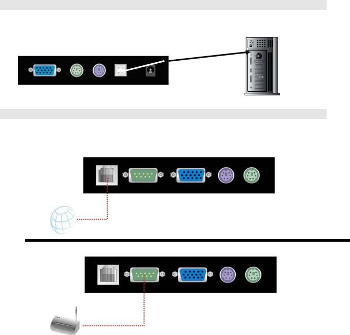
Step 8 (Option)
Connect the type A connector of USB A-B cable to the USB port of the host system, while using remote mass storage control. USB type A plug of USB A-B cable to the computer.
Step 8
Connect Ethernet and/or modem or both communication ports simultaneously, depending on how you want to access DKVM-IP1 switch
Ethernet Cable
Modem
3.2.1 Ethernet connection
The rear side of DKVM-IP1 switch provides a RJ-45 connector for Ethernet. The connector is used either for a 100 Mbps 100BASE-TX connection or for a 10 Mbps 10BASE-T connection. The adapter can sense the connection speed and will adjust to the appropriate operation mode automatically.
3.2.1.1 10 Mbps Connection
For 10BASE-T Ethernet networks, the Ethernet adapter uses Category 3, 4, 5 or 6 UTP cable. To establish a 10 Mbps connection, the cable must be connected to a 10BASE-T hub.
¾Make sure that the cable is wired appropriately for a standard 10BASE-T adapter.
¾Align the RJ-45 plug with the notch on the adapter’s connector and insert it into the adapter’s connector.
3.2.1.2.100 Mbps Connection
For 100BASE-TX Fast Ethernet networks, DKVM-IP1 switch supports Category 5 or 6 UTP cabling. To establish a 100 Mbps connection, the cable must be connected to a
10
100BASE-TX hub.
¾Make sure that the cable is wired appropriately for a standard 100BASE-TX adapter.
¾Align the RJ-45 plug with the notch on the adapter’s connector and insert it into the adapter’s connector.
3.3Scenario of connecting DKVM-IP1 switch to the Multi-port KVM Switch system
11

4. Configuration
4.1 Initial Configuration |
|
|
|
|
The DKVM-IP1 switch's communication |
interfaces are all based on TCP/IP. It comes |
|||
pre-configured with the IP configuration listed in Table 4-1. |
||||
|
|
|
|
|
|
Parameter |
|
Value |
|
|
IP auto configuration |
|
DHCP |
|
|
IP-Address |
|
- |
|
|
Net-mask |
|
255.255.255.0 |
|
|
Default-Gateway |
|
none |
|
Table 4-1. Initial network configuration
Warning
If the DHCP connection fails on boot up, the DKVM-IP1 switch will not have an IP address.
If this initial configuration does not meet your requirements, the following describes the initial IP configuration that is necessary to access the DKVM-IP1 switch for the first time.
4.1.1 Initial configuration via DHCP server
By default, the DKVM-IP1 switch will try to contact a DHCP server in the subnet to which it is physically connected. If a DHCP server is found, it may provide a valid IP address, gateway address and net mask. Before you connect the device to your local subnet, be sure to complete the corresponding configuration of your DHCP server. It is recommended to configure a fixed IP assignment to the MAC address of the DKVM-IP1 switch. You can find the MAC address labeled on the bottom side of the metal housing.
If this initial configuration does not meet your local requirements, use the setup tool to adjust the values to your needs. The setup tool can be found on the CD ROM delivered with this package.
You can follow the procedure described below.
DKVM-IP1 switch Setup Tool
MAC Address Detection
Connect the DKVM-IP1 switch to your computer either via local network, or via USB. Start the setup tool from the CD-ROM on the computer that the DKVM-IP1 switch is installed. Depending on the connection (USB or network), the device detection is different. A window opens as seen below:
12
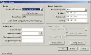
Figure4-1. DKVM-IP1 switch setup tool
On the upper left corner, the MAC address of the DKVM-IP1 switch is displayed. To detect the MAC address, manually, press the button “Refresh Devices”. The displayed MAC address is the same MAC address printed on the white sticker placed on the back of the DKVM-IP1 switch.
If the DKVM-IP1 switch is connected via USB, it is classified as an USB device and an appropriate drive letter is chosen for this device.
On the lower right corner of the window, there are two buttons: “Query Device” and “Setup
Device”. Press the “Query Device” button to display the preconfigured values of the network configuration. The values are displayed in the text fields located above. If necessary, adjust the network settings to your needs. To save the changes enter an user name and an according password. Then press the “ Setup Device “ button.
Authentication
To adjust the authentication settings, enter your login as a super user, and change your password.
Super user login
Enter the login name of the super user. The initial value is “admin”. All of characters are lower case.
Super user password
Enter the current password for the super user. This initial value is “admin”. All of characters are lower case.
New super user password
Enter the new password for the super user.
New password (confirm)
Re-type the new password for the super user.
To close the window and accept the changes, press the “ OK ” button, otherwise press the “ Cancel ” button.
4.1.2 Initial configuration via serial console
Using a serial terminal, the DKVM-IP1 switch has a serial line interface (host side). This connector is compliant with the RS 232 serial line standard. The serial line has to be configured with the parameters given in Table 4-2.
13
When configuring with a serial terminal, reset the DKVM-IP1 switch and immediately press the
“ESC ” key. You will see some device information, and a “ => ” prompt. Enter “config”, press
“Enter ” key and wait for a few seconds for the configuration questions to appear.
Parameter |
Value |
Bits/second |
115200 |
Data bits |
8 |
Parity |
No |
Stop bits |
1 |
Flow Control |
None |
Table 4-2. Serial line parameters
As you proceed, the following questions will appear on the screen. To accept the default values which are shown in square brackets below, press “Enter” key.
IP auto configuration (non/dhcp/bootp) [dhcp]:
IP [192.168.0.70]:
Net mask [255.255.255.0]:
Gateway (0.0.0.0 for none) [0.0.0.0]:
IP auto configuration
With this option, you can specify whether the DKVM-IP1 switch should get its network settings from a DHCP or BOOTP server. For DHCP, enter “dhcp”, and for BOOTP enter “bootp”. If you do not specify any of these, the IP auto configuration is disabled and subsequently you will be asked for the following network settings.
IP address
The IP address the DKVM-IP1 switch uses. This option is only available if IP auto configuration is disabled.
Net mask
The net mask of the connected IP subnet. This option is only available if IP auto configuration is disabled.
Gateway address
The IP address of the default router for the connected IP subnet. If you do not have a default router, enter 0.0.0.0. This option is only available if IP auto configuration is disabled.
4.1.3 Keyboard, Mouse and Video configuration
Between the DKVM-IP1 switch and the host, there are two interfaces available for transmitting keyboard and mouse data: USB and PS/2. The correct operation of the remote mouse depends on several settings which will be discussed in the following subsections.
4.1.3.1 DKVM-IP1 switch keyboard settings
The DKVM-IP1 switch settings for the host's keyboard type have to be corrected in order to make the remote keyboard work properly. Check the settings in the DKVM-IP1 switch front-end. See section 6.4.3 in details.
14

4.1.3.2 Remote Mouse Settings
A common problem with KVM devices is the synchronization between the local and remote mouse cursors. The DKVM-IP1 switch addresses this situation with an intelligent synchronization algorithm. There are two mouse modes available on the DKVM-IP1 switch.
Auto mouse speed
The automatic mouse speed mode tries to detect the speed and acceleration settings of the host system automatically. See the section below for a more detailed explanation.
Fixed mouse speed
This mode just translates the mouse movements from the Remote Console in a way that one pixel move will lead to n pixel moves on the remote system. This parameter n is adjustable with the scaling. It should be noted that this works only when mouse acceleration is turned off on the remote system.
4.1.3.3 Auto mouse speed and mouse synchronization
The automatic mouse speed mode performs the speed detection during mouse synchronization. Whenever the mouse does not move correctly, there are two ways for re-synchronizing local and remote mouse:
Fast Sync
The fast synchronization is used to correct a temporary, but fixed skew. Choose the option using the Remote Console options menu or press the mouse synchronization hotkey sequence in case you defined one.
Intelligent Sync
If the fast sync does not work or the mouse settings have been changed on the host system, use the intelligent resynchronization. This method takes more time than the fast one and can be accessed with the appropriate item in the Remote Console option menu.
The intelligent synchronization requires a correctly adjusted picture. Use the auto adjustment function or the manual correction in the Video Settings panel to setup the picture. The Sync mouse button on top of the Remote Console can behave differently, depending on the current state of mouse synchronization. Usually pressing this button leads to a fast sync, except in situations where the KVM port or the video mode changed recently.
Note: At first start, if the local mouse pointer is not synchronized with the remote mouse pointer, press the Auto Adjust Button once.
4.1.3.4 Host system mouse settings
The host's operating system knows various settings from the mouse driver.
Warning
The following limitations do not apply in case of USB and Mouse Type “MS Windows 2000 and newer”.
While the DKVM-IP1 switch works with accelerated mice and is able to synchronize the local with the remote mouse pointer, there are the following limitations, which may prevent this synchronization from working properly:
15
Special Mouse Driver
There are mouse drivers which influence the synchronization process and lead to desynchronized mouse pointers. If this happens, make sure you do not use a special vendor-specific mouse driver on your host system.
Windows XP Mouse Settings
Windows XP knows a setting named “improve mouse acceleration”, which has to be deactivated.
Active Desktop
If the Active Desktop feature of Microsoft Windows is enabled do not use a plain background. Instead, use some kind of wallpaper. As an alternative, you could also disable the Active Desktop completely.
Navigate your mouse pointer into the upper left corner of the applet screen and move it slightly forth and back. Thus the mouse will be resynchronized. If re-synchronizing fails, disable the mouse acceleration and repeat the procedure.
4.1.3.5 Single and Double Mouse Mode
The information above applies to the Double Mouse Mode, where remote and local mouse pointers are visible and need to by synchronize. The DKVM-IP1 switch also features another mode, the Single Mouse Mode, where only the remote mouse pointer is visible. Activate this mode in the open Remote Console and click into the window area. The local mouse pointer will be hidden and the remote one can be controlled directly. To leave this mode, it is necessary to define a mouse hotkey in the Remote Console Settings Panel. Press this key to free the captured local mouse pointer.
4.1.3.6 Recommended Mouse Settings
For the different operating systems we can give the following advice:
MS Windows 2000/2003 (Professional and Server)
XP In general, we recommend the usage of a mouse via USB. Choose USB without Mouse Sync. For a PS/2 mouse choose Auto Mouse Speed. For XP disable the option enhance pointer precision in the Control Panel.
SUN Solaris
Adjust the mouse settings either via xset m 1 or use the CDE Control Panel to set the mouse to 1:1, no acceleration. As an alternative you may also use the Single Mouse Mode.
MAC OS X
We recommend using the Single Mouse Mode.
4.1.3.7 Video Modes
The DKVM-IP1 switch recognizes a limited number of common video modes. When running
X11 on the host system, please do not use any custom mode lines with special video modes. If you do, the DKVM-IP1 switch may not be able to detect them. We recommend using any of the standard VESA video modes, instead.
16
5.Usage
5.1Prerequisites
The DKVM-IP1 switch features an embedded operating system and applications offering a variety of standardized interfaces. This chapter will describe both these interfaces, and the way to use them in a more detailed manner. The interfaces are accessed using the TCP/IP protocol family, thus they can be accessed using the built-in Ethernet adapter.
The following interfaces are supported:
HTTP/HTTPS
Full access is provided by the embedded web server. The DKVM-IP1 switch environment can be entirely managed using a standard web browser. You can access the DKVM-IP1 switch using the insecure HTTP protocol, or using the encrypted HTTPS protocol. Whenever possible, use HTTPS.
Telnet
A standard Telnet client can be used to access an arbitrary device connected to the
DKVM-IP1 switch's serial port via a terminal mode.
The primary interface of the DKVM-IP1 switch is the HTTP interface. This is covered extensively in this chapter. Other interfaces are addressed in subtopics.
In order to use the Remote Console window of your managed host system, the browser has to come with a Java Runtime Environment version 1.1 or higher. If the browser has no Java support (such as on a small handheld device), you are still able to maintain your remote host system using the administration forms displayed by the browser itself.
Important: We recommend installing a Sun JVM 1.4.
For an insecure connection to the DKVM-IP1 switch, we can recommend the following browsers:
•Microsoft Internet Explorer version 6.0 or higher on Windows 98, Windows ME, Windows 2000 and Windows XP
•Netscape Navigator 7.0 or Mozilla 1.6 on Windows 98, Windows ME, Windows 2000, Windows XP, Linux and other UNIX-like Operating Systems
In order to access the remote host system using a securely encrypted connection, you need a browser that supports the HTTPS protocol. Strong security is only assured by using a key length of 128 Bit. Some of the old browsers do not have a strong 128 Bit encryption algorithm.
Using the Internet Explorer, open the menu entry “?” and “Info” to read about the key length that is currently activated. The dialog box contains a link that leads you to information on how to upgrade your browser to a state of the art encryption scheme. Figure 5-1 shows the dialog box presented by the Internet Explorer 6.0.
17
Figure 5-1. The Internet Explorer displaying the encryption key length
Newer web browsers do support strong encryption on default.
5.2 Login into the DKVM-IP1 switch and logout
5.2.1 Login into the DKVM-IP1 switch
Launch your web browser. Direct it to the address of your DKVM-IP1 switch, which you configured during the installation process. The address used might be a plain IP address or a host and domain name, in the case where you have given your DKVM-IP1 switch a symbolic name in the DNS. For instance, type the following in the address line of your browser when establishing an unsecured connection:
http://<IP address of DKVM-IP1>
When using a secure connection, type in: https://<IP address of DKVM-IP1>
This will lead you to the DKVM-IP1 switch login page as shown in Figure 5-2.
Figure 5-2. Login screen
The DKVM-IP1 switch has a built-in super user that has all permissions to administrate your
DKVM-IP1 switch:
Login name |
admin (factory default) |
Password |
admin (factory default) |
Table 5-1. Standard user settings
18
Warning
The user “ super ” is not allowed to login via the serial interface of the DKVM-IP1 switch.
Warning
Please make sure to change the super user password immediately after you have installed and accessed your DKVM-IP1 switch for the first time. Not changing the pass phrase for the super user is a severe security risk and might result in unauthorized access to the DKVM-IP1 switch and to the host system including all possible consequences!
Warning
Your web browser has to accept cookies, or else login is not possible.
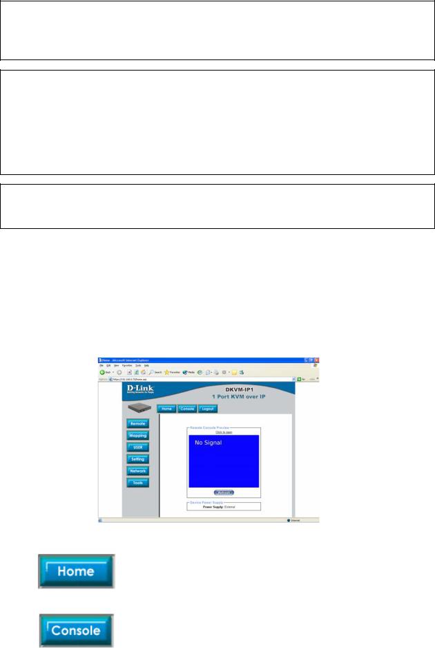
Navigation
Having logged into the DKVM-IP1 switch successfully, the main page of the DKVM-IP1 switch appears (see Figure 5-3). This page consists of three parts; each of them contains specific information. The buttons on the upper side allow you to navigate within the front end (see Table 5-2 for details). The lower left frame contains a navigation bar and allows you to switch between the different sections of the DKVM-IP1 switch. Within the right frame, task-specific information is displayed that depends on the section you have chosen before.
Figure 5-3. Main page
Return to the main page of the DKVM-IP1 switch .
Open the DKVM-IP1 switch remote console.
19
 Loading...