


FCC Information and Copyright
This equipment has been tested and found to comply with the limits of a Class B digital device, pursuant to Part 15 of the FCC Rules. These limits are designed to provide reasonable protection against harmful interference in a residential installation. This equipment generates, uses, and can radiate radio frequency energy and, if not installed and used in accordance with the instructions, may cause harmful interference to radio communications. There is no guarantee that interference will not occur in a particular installation.
The vendor makes no representations or warranties with respect to the contents here and specially disclaims any implied warranties of merchantability or fitness for any purpose. Further the vendor reserves the right to revise this publication and to make changes to the contents here without obligation to notify any party beforehand.
Duplication of this publication, in part or in whole, is not allowed without first obtaining the vendor’s approval in writing.
The content of this user’s manual is subject to be changed without notice and we will not be responsible for any mistakes found in this user’s manual. All the brand and product names are trademarks of their respective companies.
Dichiarazione di conformità sintetica
Ai sensi dell’art. 2 comma 3 del D.M. 275 del 30/10/2002
Si dichiara che questo prodotto è conforme alle normative vigenti e soddisfa i requisiti essenziali richiesti dalle direttive
2004/108/CE, 2006/95/CE e 1999/05/CE quando ad esso applicabili
Short Declaration of conformity
We declare this product is complying with the laws in force and meeting all the essential requirements as specified by the directives
2004/108/CE, 2006/95/CE and 1999/05/CE whenever these laws may be applied

Table Of Contents
FCC Information and Copyright 1 Chapter 1: Introduction 3
1.1 Before You Start 3
1.2 Package Checklist 3
1.3 Specifications 4
1.4 Rear Panel Connectors 5
1.5 Motherboard Layout 6
Chapter 2: Hardware installation 7
2.1 Install Central Processing Unit (CPU) 7
2.2 Install a Heatsink 9
2.3 Connect Cooling Fans 10
2.4 Install System Memory 10
2.5 Expansion Slots 12
2.6 Jumper & Switch Setting 13
2.7 Headers & Connectors 14
Chapter 3: UEFI BIOS & Software 17
3.1 UEFI BIOS Setup 17
3.2 BIOS Update 17
3.3 Software 21
Chapter 4: Useful help 22
4.1 Driver Installation 22
4.2 AMI BIOS Beep Code 23
4.3 AMI BIOS post code 23
4.4 Troubleshooting 25
APPENDIX I: Specifications in Other Languages 26
Arabic...................................................................................................................................... |
26 |
German................................................................................................................................... |
27 |
Russian.................................................................................................................................... |
28 |
Spanish ................................................................................................................................... |
29 |
Thai ......................................................................................................................................... |
30 |
Japan |
31 |
2 | Table Of Contents

H410MH / H410MHP 
Chapter 1: Introduction
1.1 Before You Start
Thank you for choosing our product. Before you start installing the motherboard, please make sure you follow the instructions below:
• Prepare a dry and stable working environment with sufficient lighting. • Always disconnect the computer from power outlet before operation.
• Before you take the motherboard out from anti-static bag, ground yourself properly by touching any safely grounded appliance, or use grounded wrist strap to remove the static charge.
• Avoid touching the components on motherboard or the rear side of the board unless necessary. Hold the board on the edge, do not try to bend or flex the board.
• Do not leave any unfastened small parts inside the case after installation. Loose parts will cause short circuits which may damage the equipment.
• Keep the computer from dangerous area, such as heat source, humid air and water. • The operating temperatures of the computer should be 0 to 45 degrees Celsius. • To avoid injury, be careful of:
Sharp pins on headers and connectors
Rough edges and sharp corners on the chassis Damage to wires that could cause a short circuit
1.2Package Checklist
• Serial ATA Cable x2
• Rear I/O Panel for ATX Case x1 • Quick Installation Guide x1 • Fully Setup Driver DVD x1
 Note
Note
» The package contents may be different due to the sales region or models in which it was sold. For more information about the standard package in your region, please contact your dealer or sales representative.
Chapter 1: Introduction | 3

1.3 Specifications
Specifications
|
Socket 1200 for 10th Gen Intel® Core™, Pentium and Celeron processors |
|
CPU Support |
* 10th Generation Intel® Core™ Processor Family only support 400-Series. |
|
|
* Please refer to www.biostar.com.tw for CPU support list. |
|
|
|
|
Chipset |
INTEL® H410 |
|
|
Supports Dual Channel DDR4 1866/ 2133/ 2400/ 2666/ 2933 |
|
Memory |
2x DDR4 DIMM Memory Slot, Max. Supports up to 64 GB Memory |
|
Each DIMM supports non-ECC 4/8/16/32GB DDR4 module |
||
|
||
|
* Please refer to www.biostar.com.tw for Memory support list. |
|
|
|
|
|
4x SATA III Connector (6Gb/s) |
|
|
1x M.2 (M Key) Socket (H410MH Only): |
|
Storage |
Supports M.2 Type 2242/ 2260/ 2280 SSD module. |
|
|
Supports PCI-E 2.0 x2 (10Gb/s) & SATA III (6Gb/s) SSD |
|
|
* When using SATA SSD module on PCIE-M2_1 slot, the SATA_1 connector will be disabled. |
|
LAN |
RTL8111H |
|
10/ 100/ 1000 Mb/s auto negotiation, Half / Full duplex capability |
||
|
||
Audio Codec |
ALC887 |
|
7.1 Channels, High Definition Audio |
||
|
||
USB |
4x USB 3.2(Gen1) port (2 on rear I/Os and 2 via internal headers) |
|
6x USB 2.0 port (4 on rear I/Os and 2 via internal headers) |
||
|
||
|
|
|
Expansion Slots |
2x PCIe 2.0 x1 Slot |
|
1x PCIe 3.0 x16 Slot |
||
|
||
|
1x PS/2 Keyboard |
|
|
1x PS/2 Mouse |
|
|
1x HDMI Port |
|
Rear I/Os |
1x VGA Port |
|
2x USB 3.2 (Gen1) Port |
||
|
||
|
4x USB 2.0 Port |
|
|
1x LAN port |
|
|
3x Audio Jack |
|
|
4x SATA III Connector (6Gb/s) |
|
|
1x USB 2.0 Header (each header supports 2 USB 2.0 ports) |
|
|
1x USB 3.2 (Gen1) Header (each header supports 2 USB 3.2 (Gen1) ports) |
|
|
1x 8-Pin Power Connector |
|
|
1x 24-Pin Power Connector |
|
Internal I/Os |
1x CPU Fan Connector |
|
|
1x System Fan Connector |
|
|
1x Front Panel Header |
|
|
1x Front Audio Header |
|
|
1x Clear CMOS Header |
|
|
1x COM Port Header |
|
Form Factor |
uATX Form Factor, 226 mm x 179 mm |
|
|
|
|
OS Support |
Windows 10(64bit) |
|
* Biostar reserves the right to add or remove support for any OS with or without notice. |
||
|
4 | Chapter 1: Introduction

H410MH / H410MHP 
1.4Rear Panel Connectors
 Note
Note
» HDMI/ VGA ports only work with an Intel® integrated Graphics Processor. » Maximum resolution
HDMI: 4096 x 2160 @24Hz, compliant with HDMI 1.4 VGA: 1920 x 1200 @60Hz
When using the front HD audio jack and plug in the headset / microphone , the rear sound will be automaticallyDisabled.
» The mainboard supports two onboard display outputs at same time and the display output configuration can be selected in Intel graphics driver utility.
Chapter 1: Introduction | 5

1.5 Motherboard Layout
 Note
Note
»  represents the 1st pin.
6 | Chapter 1: Introduction

H410MH / H410MHP 
Chapter 2: Hardware installation
2.1 Install Central Processing Unit (CPU)
Step 1: Locate the CPU socket on the motherboard
 Note
Note
» Remove pin cap before installation, and make good preservation for future use. When the CPU is
removed, cover the pin cap on the empty socket to ensure pin legs won’t be damaged.
» The motherboard might equip with two different types of pin cap. Please refer below instruction to
remove the pin cap.
Step 2: Pull the socket locking lever out from the socket and then raise the lever up.
Step 3: Remove the Pin Cap.
Chapter 2: Hardware installation | 7
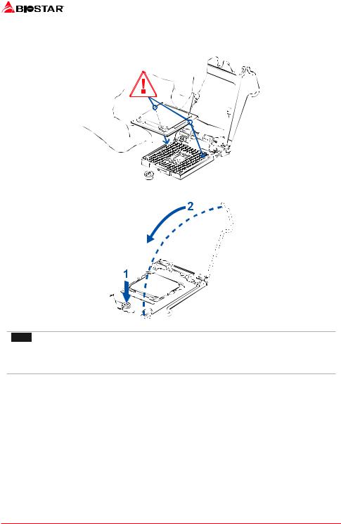
Step 4: Hold processor with your thumb and index fingers, oriented as shown. Align the notches with the socket. Lower the processor straight down without tilting or sliding the processor in the socket.
Step 5: Hold the CPU down firmly, and then lower the lever to locked position to complete the installation.
 Note
Note
» Ensure that you install the correct CPU designed for LGA1200 socket.
» The CPU fits only in one correct orientation. Do not force the CPU into the socket to prevent
damaging the CPU.
8 | Chapter 2: Hardware installation

H410MH / H410MHP 
2.2 Install a Heatsink
Step 1: Place the CPU fan assembly on top of the installed CPU and make sure that the four fasteners match the motherboard holes. Orient the assembly and make the fan cable is closest to the CPU fan connector.
Step 2: Press down two fasteners at one time in a diagonal sequence to secure the CPU fan assembly in place. As each fastener locks into position a click should be heard.
 Note
Note
» Apply the thermal interface material on the CPU before heatsink installation, if necessary.
» Do not forget to connect the CPU fan connector.
» For proper installation, please kindly refer to the installation manual of your CPU heatsink.
Chapter 2: Hardware installation | 9

2.3 Connect Cooling Fans
These fan headers support cooling-fans built in the computer. The fan cable and connector may be different according to the fan manufacturer.
CPU_FAN1: CPU Fan Header
|
|
|
|
|
|
|
|
|
|
|
|
|
|
|
|
|
|
|
|
|
|
|
|
|
|
|
|
|
|
|
|
|
|
|
|
|
|
|
|
|
|
|
|
|
|
|
|
|
|
|
|
|
|
|
|
|
|
|
|
|
|
|
|
|
|
|
|
|
|
|
|
|
|
|
|
|
|
|
|
|
|
|
|
|
|
|
|
|
|
|
|
|
|
|
|
|
|
|
|
|
|
|
|
|
|
|
|
|
|
|
|
|
|
Pin |
Assignment |
|
|
|
|
|
|
|
|
|
|
|
|
|
|
|
|
|
|
|
|
|
|
|
|
|
|
|
||
|
|
|
|
|
|
|
|
|
|
|
|
|
|
|
|
|
|
|
|
|
|
|
|
|
|
1 |
Ground |
|
|
|
|
|
|
|
|
|
|
|
|
|
|
|
|
|
|
|
|
|
|
|
|
|
|
||||
|
|
|
|
|
|
|
|
|
|
|
|
|
|
|
|
|
|
|
|
|
|
|
|
|
|
2 |
+12V |
|
|
|
|
|
|
|
|
|
|
|
|
|
|
|
|
|
|
|
|
|
|
|
|
|
|
||||
|
|
|
|
|
|
|
|
|
|
|
|
|
|
|
|
|
|
|
|
|
|
|
|
|
||||
|
|
|
|
|
|
|
|
|
|
|
|
|
|
|
|
|
|
|
|
|
|
|
|
|
|
3 |
FAN RPM rate sense |
|
|
|
|
|
|
|
|
|
|
|
|
|
|
|
|
|
|
|
|
|
|
|
|
|
|
|
|
|
|
|
|
|
|
|
|
|
|
|
|
|
|
|
|
|
|
|
|
|
|
|
|
|
|
|
|
4 |
AI Fan Control (By FAN) |
|
|
|
|
|
|
|
|
|
|
|
|
|
|
|
|
|
|
|
|
|
|
|
|
|
|
|
|
|
|
|
|
|
|
|
|
|
|
|
|
|
|
|
|
|
|
|
|
|
|
|
|
|
|
|
|
|
|
|
|
|
|
|
|
|
|
|
|
|
|
|
|
|
|
|
|
|
|
|
|
|
|
|
|
|
|
|
|
SYS_FAN1: System Fan Header
|
|
|
|
|
|
|
|
|
|
|
|
|
|
|
|
|
|
|
|
|
|
|
|
|
|
|
|
|
|
|
|
|
|
|
|
|
|
|
|
|
|
|
|
|
|
|
|
|
|
|
|
|
|
|
|
|
|
|
|
|
|
|
|
|
|
|
|
|
|
|
|
|
|
|
|
|
|
|
|
|
|
|
|
|
|
|
|
|
|
|
|
|
|
|
|
|
|
|
|
|
|
|
|
|
|
|
|
|
|
|
|
|
|
|
|
|
|
|
|
|
|
|
|
|
Pin |
Assignment |
|
|
|
|
|
|
|
|
|
|
|
|
|
|
|
|
|
|
|
|
|
|
|
|
|
|
|
|
|
|
|
||
|
|
|
|
|
|
|
|
|
|
|
|
|
|
|
|
|
|
|
|
|
|
|
|
|
|
|
|
1 |
Ground |
|
|
|
|
|
|
|
|
|
|
|
|
|
|
|
|
|
|
|
|
|
|
|
|
|
|
|
|
|
|
||||
|
|
|
|
|
|
|
|
|
|
|
|
|
|
|
|
|
|
|
|
|
|
|
|
|
|
|
|
2 |
+12V |
|
|
|
|
|
|
|
|
|
|
|
|
|
|
|
|
|
|
|
|
|
|
|
|
|
|
|
|
|
|
||||
|
|
|
|
|
|
|
|
|
|
|
|
|
|
|
|
|
|
|
|
|
|
|
|
|
|
|
|
||||
|
|
|
|
|
|
|
|
|
|
|
|
|
|
|
|
|
|
|
|
|
|
|
|
|
|
|
|
3 |
FAN RPM rate sense |
|
|
|
|
|
|
|
|
|
|
|
|
|
|
|
|
|
|
|
|
|
|
|
|
|
|
|
|
|
|
4 |
AI Fan Control (By FAN) |
|
|
|
|
|
|
|
|
|
|
|
|
|
|
|
|
|
|
|
|
|
|
|
|
|
|
|
|
|
|
|
|
|
|
|
|
|
|
|
|
|
|
|
|
|
|
|
|
|
|
|
|
|
|
|
|
|
|
|
|
|
|
|
|
|
|
|
|
|
|
|
|
|
|
|
|
|
|
|
|
|
|
|
|
|
|
|
|
|
|
|
|
|
|
|
|
|
|
|
|
|
|
|
|
|
|
|
|
|
|
|
|
|
|
|
|
|
|
|
|
|
|
|
|
|
|
|
|
|
|
 Note
Note
» CPU_FAN1, SYS_FAN1 support 4-pin and 3-pin head connectors. When connecting with wires onto connectors, please note that the red wire is the positive and should be connected to pin#2, and the black wire is Ground and should be connected to pin#1(GND).
2.4 Install System Memory
DDR4 Modules
10 | Chapter 2: Hardware installation
H410MH / H410MHP 
Step 1: Unlock a DIMM slot by pressing the retaining clips outward. Align a DIMM on the slot such that the notch on the DIMM matches the break on the slot.
Step 2: Insert the DIMM vertically and firmly into the slot until the retaining clips snap back in place and the DIMM is properly seated.
 Note
Note
» If the DIMM does not go in smoothly, do not force it. Pull it all the way out and try again.
Memory Capacity
|
|
|
|
DIMM Socket Location |
DDR4 Module |
Total Memory Size |
|
DIMMA1 |
4GB/8GB/16GB/32GB |
Max is 64GB. |
|
DIMMB1 |
4GB/8GB/16GB/32GB |
||
|
Dual Channel Memory Installation
Please refer to the following requirements to activate Dual Channel function:
Install memory module of the same density in pairs, shown in the table.
Dual Channel Status |
DIMMA1 |
DIMMB1 |
Disabled |
O |
X |
Disabled |
X |
O |
Enabled |
O |
O |
(O means memory installed, X means memory not installed.)
 Note
Note
» When installing more than one memory module, we recommend to use the same brand and
capacity memory on this motherboard.
Chapter 2: Hardware installation | 11

2.5 Expansion Slots
PEX16_1: PCI-Express Gen3 x16 Slot
• PCI-Express 3.0 compliant.
• Theoretical maximum bandwidth using two slots simultaneously is 16GB/s for each slot, a total of 32GB/s.
PEX1_1/ PEX1_2: PCI-Express Gen2 x1 Slots
• PCI-Express 2.0 compliant.
• Data transfer bandwidth up to 500MB/s per direction; 1GB/s in total
PCIE-M2_1: M.2 (M Key) Socket
• The M.2 slot supports M.2 Type 2242/2260/2280 SSD module. When installing M.2 SSD module, please place the screw and hex pillar to correct position.
• Supports M.2 SATA III (6Gb/s) module and M.2 PCI Express module up to Gen2 x2 (10Gb/s).
 Note
Note
»» When using SATA SSD module on PCIE-M2_1 slot, the SATA_1 connector will be disabled.
Install an Expansion Card
You can install your expansion card by following steps:
• Read the related expansion card’s instruction document before install the expansion card into the computer.
• Remove your computer’s chassis cover, screws and slot bracket from the computer.
• Place a card in the expansion slot and press down on the card until it is completely seated in the slot.
• Secure the card’s metal bracket to the chassis back panel with a screw. (This step is only forinstallingaVGAcard.).
• Replace your computer’s chassis cover.
• Power on the computer, if necessary, change BIOS settings for the expansion card. • Install related driver for the expansion card.
 Note
Note
»» Please be note that you will need to use M2 type screwdriver if you want to install or uninstall the screw. It is recommended not to use a screwdriver that does not meet the specifications, otherwise the screw may be damaged.
12 | Chapter 2: Hardware installation

H410MH / H410MHP 
2.6 Jumper & Switch Setting
The illustration shows how to set up jumpers. When the jumper cap is placed on pins, the jumper is “close”, if not, that means the jumper is “open”.
Pin opened |
Pin closed |
Pin 1-2 closed |
JCMOS1: Clear CMOS Jumper
The jumper allows users to restore the BIOS safe setting and the CMOS data. Please carefully follow the procedures to avoid damaging the motherboard.
Pin 1-2 Open: Normal Operation (Default)
Pin 1-2 Short: Clear CMOS data
Clear CMOS Procedures:
1.Remove AC power line.
2.Set the jumper to “Pin 1-2 Short”, you can use a metal object like a screwdriver to touch the two pins.
3.Wait for five seconds.
4.After clearing the CMOS values, be sure the jumper is “Pin 1-2 open”.
5.Power on the AC.
6.Load Optimal Defaults and save settings in CMOS.
Chapter 2: Hardware installation | 13

2.7 Headers & Connectors
ATXPWR1: ATX Power Source Connector
For better compatibility, we recommend to use a standard ATX 24-pin power supply for this connector. Make sure to find the correct orientation before plugging the connector.
Pin |
Assignment |
Pin |
Assignment |
13 |
+3.3V |
1 |
+3.3V |
14 |
-12V |
2 |
+3.3V |
15 |
Ground |
3 |
Ground |
16 |
PS_ON |
4 |
+5V |
17 |
Ground |
5 |
Ground |
18 |
Ground |
6 |
+5V |
19 |
Ground |
7 |
Ground |
20 |
NC |
8 |
PW_OK |
21 |
+5V |
9 |
Standby Voltage+5V |
22 |
+5V |
10 |
+12V |
23 |
+5V |
11 |
+12V |
24 |
Ground |
12 |
+3.3V |
ATXPWR2: ATX Power Source Connector
The connector provides +12V to the CPU power circuit. If the CPU power plug is 4-pin, please plug it into Pin 1-2-5-6 of ATXPWR2.
|
|
|
|
|
|
|
|
|
|
|
|
|
|
|
|
|
|
|
|
|
|
|
|
|
|
|
|
|
|
|
|
|
|
|
|
|
|
|
|
|
|
|
|
|
|
|
|
|
|
|
Pin |
Assignment |
|
|
|
|
|
|
|
|
|
|
|
|
|
|
|
|
|
|
|
|
|
|
|
|
|
|
||
|
|
|
|
|
|
|
|
|
|
|
|
|
|
|
|
|
|
|
|
|
|
|
|
1 |
+12V |
|
|
|
|
|
|
|
|
|
|
|
|
|
|
|
|
|
|
|
|
|
|
|
|
|
|
||
|
|
|
|
|
|
|
|
|
|
|
|
|
|
|
|
|
|
|
|
|
|
2 |
+12V |
|
||
|
|
|
|
|
|
|
|
|
|
|
|
|
|
|
|
|
|
|
|
|
|
|
|
|
||
|
|
|
|
|
|
|
|
|
|
|
|
|
|
|
|
|
|
|
|
3 |
+12V |
|
||||
|
|
|
|
|
|
|
|
|
|
|
||||||||||||||||
|
|
|
|
|
|
|
|
|
|
|
|
|||||||||||||||
|
|
|
|
|
|
|
|
|
|
|
|
|
|
|
|
4 |
+12V |
|
||||||||
|
|
|
|
|
|
|
|
|
|
|
||||||||||||||||
|
|
|
|
|
|
|
|
|
|
|
|
|
|
|
|
|
|
|
||||||||
|
|
|
|
|
|
|
|
|
|
|
|
|
|
|
|
5 |
Ground |
|
||||||||
|
|
|
|
|
|
|
|
|
|
|
|
|
|
|
|
|
||||||||||
|
|
|
|
|
|
|
|
|
|
|
||||||||||||||||
|
|
|
|
|
|
|
|
|
|
|
|
|
|
|
|
6 |
Ground |
|
||||||||
|
|
|
|
|
|
|
|
|
|
|
||||||||||||||||
|
|
|
|
|
|
|
|
|
|
|
|
|
|
|
|
7 |
Ground |
|
||||||||
|
|
|
|
|
|
|
|
|
|
|
|
|
|
|
|
|
|
|
|
|
|
|
|
|
||
|
|
|
|
|
|
|
|
|
|
|
|
|
|
|
|
|
|
|
|
|
|
|
|
|
||
|
|
|
|
|
|
|
|
|
|
|
|
|
|
|
|
|
|
|
|
|
|
|
|
|
||
|
|
|
|
|
|
|
|
|
|
|
|
|
|
|
|
|
|
|
|
|
|
|
|
8 |
Ground |
|
|
|
|
|
|
|
|
|
|
|
|
|
|
|
|
|
|
|
|
|
|
|
|
|
|
||
|
|
|
|
|
|
|
|
|
|
|
|
|
|
|
|
|
|
|
|
|
|
|
|
|
|
|
|
|
|
|
|
|
|
|
|
|
|
|
|
|
|
|
|
|
|
|
|
|
|
|
|
|
|
|
|
|
|
|
|
|
|
|
|
|
|
|
|
|
|
|
|
|
|
|
|
|
|
|
|
|
 Note
Note
» Before you power on the system, please make sure that both ATXPWR1 and ATXPWR2 connectors have been plugged-in.
» Insufficient power supplied to the system may result in instability or the peripherals not functioning properly. Use of a PSU with a higher power output is recommended when configuring a system with more power-consuming devices.
14 | Chapter 2: Hardware installation
H410MH / H410MHP 
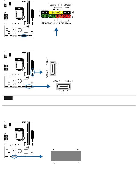
PANEL1: Front Panel Header
This 16-pin header includes Power-on, Reset, HDD LED, Power LED, and speaker connection.
|
|
|
|
|
|
|
|
|
|
|
|
|
|
|
|
|
|
|
|
|
|
|
|
|
|
|
|
|
|
|
|
|
|
|
|
|
|
|
|
|
|
|
|
|
|
|
|
Pin |
Assignment |
Function |
Pin |
Assignment |
Function |
|
|
|
|
|
|
|
|
|
|
|
|
|
|
|
|
|
|
|
|
|
|
|
|
|
|
|
|
|
|
|
|
|
|
|
|
|
|
|
|
|
|
|
|
|
1 |
+5V |
|
9 |
N/A |
N/A |
|||
|
|
|
|
|
|
|
|
|
|
|
|
|
|
|||||||||||||
|
|
|
|
|
|
|
|
|
|
|
|
|
|
|
|
|
|
|
|
|
|
|
|
|
|
|
|
|
|
|
|
|
|
|
|
|
|
|
|
|
|
|
|
|
|
|
|
2 |
N/A |
Speaker |
10 |
N/A |
|
|
|
|
|
|
|
|
|
|
|
|
|
|
|
|
|
|
|
|
||||||||
|
|
|
|
|
|
|
|
|
|
|
|
|
|
|
|
|
|
3 |
N/A |
Connector |
11 |
N/A |
N/A |
|||
|
|
|
|
|
|
|
|
|
|
|
|
|
|
|
|
|
|
|
|
|
|
|
|
|
|
|
|
|
|
|
|
|
|
|
|
|
|
|
|
|
|
|
|
|
4 |
Speaker |
|
12 |
Power LED (+) |
Power |
|||
|
|
|
|
|
|
|
|
|
|
|
|
|
|
|
|
|
|
|
||||||||
|
|
|
|
|
|
|
|
|
|
|
|
|
|
|
|
|
|
5 |
HDD LED (+) |
Hard drive |
13 |
Power LED (+) |
LED |
|||
|
|
|
|
|
|
|
|
|
|
|
|
|
|
|
|
|
|
|
|
|
6 |
HDD LED (-) |
LED |
14 |
Power LED (-) |
|
|
|
|
|
|
|
|
|
|
|
|
|
|
|
|
|
|
|
|
|
|
|
|||||
|
|
|
|
|
|
|
|
|
|
|
|
|
|
|
|
|
|
|
|
|
|
|||||
|
|
|
|
|
|
|
|
|
|
|
|
|
|
|
|
|
|
|
|
|
|
|
|
|
|
|
|
|
|
|
|
|
|
|
|
|
|
|
|
|
|
|
|
|
|
|
7 |
Ground |
Reset |
15 |
Power button |
Power-on |
|
|
|
|
|
|
|
|
|
|
|
|
|
|
|
|
|
|
|
|
|
|
8 |
Reset control |
button |
16 |
Ground |
button |
|
|
|
|
|
|
|
|
|
|
|
|
|
|
|
|
|
|
|
|
|
||||||
|
|
|
|
|
|
|
|
|
|
|
|
|
|
|
|
|
|
|
|
|
|
|
|
|
|
|
|
|
|
|
|
|
|
|
|
|
|
|
|
|
|
|
|
|
|
|
|
|
|
|
|
|
|
SATA_1/ SATA_2/ SATA_3/ SATA_4: Serial ATA Connectors
These connectors connect to SATA hard disk drives via SATA cables.
|
|
|
|
|
|
|
|
|
|
|
|
|
|
|
|
|
|
|
|
|
|
|
|
|
|
|
|
|
|
|
|
|
|
|
|
|
|
|
|
|
|
|
|
|
|
|
|
|
|
|
|
|
|
|
|
|
|
|
|
|
|
|
|
|
|
|
|
|
|
|
|
|
|
|
|
|
|
|
|
|
|
|
|
|
|
|
|
|
|
|
|
|
|
|
|
|
Pin |
Assignment |
|
|
|
|
|
|
|
|
|
|
|
|
|
|
|
|
|
|
|
|
|
|
|
|
|
|
|
|
|
||||
|
|
|
|
|
|
|
|
|
|
|
|
|
|
|
|
|
|
|
|
|
|
|
|
|
|
|
|
|
|
|
|
|
|
|
|
|
|
|
|
|
|
|
|
|
|
|
|
|
|
|
|
|
|
1 |
Ground |
||||||||||
|
|
|
|
|
|
|
|
|
|
|
|
|
|
|
|
|
|
|
|
|
|
|
|
|
|
|
|
|
|
|
||
|
|
|
|
|
|
|
|
|
|
|
|
|
|
|
|
|
|
|
|
|
|
|
2 |
TX+ |
||||||||
|
|
|
|
|
|
|
|
|
|
|
|
|
|
|
|
|
|
|
|
|
|
|
|
|
|
|
|
|
|
|
|
|
|
|
|
|
|
|
|
|
|
|
|
|
|
|
|
|
|
|
|
|
|
|
3 |
TX- |
|||||||||
|
|
|
|
|
|
|
|
|
|
|
|
|
|
|
|
|
|
|
|
|
|
4 |
Ground |
|||||||||
|
|
|
|
|
|
|
|
|
|
|
|
|
|
|
|
|
|
|
|
|
|
5 |
RX- |
|||||||||
|
|
|
|
|
|
|
|
|
|
|
|
|
|
|
|
|
|
|
|
|
|
|
|
|
|
|
|
|
|
|
||
|
|
|
|
|
|
|
|
|
|
|
|
|
|
|
|
|
|
|
|
|
|
|
|
|
|
|
|
|
|
|
||
|
|
|
|
|
|
|
|
|
|
|
|
|
|
|
|
|
|
|
|
|
|
|
|
|
|
|
|
|
|
|
|
|
|
|
|
|
|
|
|
|
|
|
|
|
|
|
|
|
|
|
6 |
RX+ |
|||||||||||||
|
|
|
|
|
|
|
|
|
|
|
|
|
|
|
|
|
|
|
|
|
|
|
|
|
|
|
|
|
|
|
7 |
Ground |
|
|
|
|
|
|
|
|
|
|
|
|
|
|
|
|
|
|
|
|
|
|
|
|
|
|
|
|
|
|
|
|
|
|
|
|
|
|
|
|
|
|
|
|
|
|
|
|
|
|
|
|
|
|
|
|
|
|
|
|
|
|
|
|
|
|
|
|
|
|
|
|
|
|
|
|
|
|
|
|
|
|
|
|
|
|
|
|
|
|
|
|
|
|
|
|
|
|
|
 Note
Note
»» When using SATA SSD module on PCIE-M2_1 slot, the SATA_1 connector will be disabled.
JFRONT_USB3_1: Header for USB 3.2 (Gen1) Ports at Front Panel
This header allows user to add additional USB ports on the PC front panel, and also can be connected with a wide range of external peripherals.
|
|
|
|
|
|
|
|
|
|
|
|
|
|
|
|
|
|
|
|
|
|
|
|
|
|
|
Pin |
Assignment |
Pin |
Assignment |
|
|
|
|
|
|
|
|
|
|
|
|
|
|
|
|
|
|
|
|
|
|
|
|
|
|
|
||||
|
|
|
|
|
|
|
|
|
|
|
|
|
|
|
|
|
|
|
|
|
|
|
|
|
|
|
|
|
|
|
|
|
|
|
|
|
|
|
|
|
|
|
|
|
|
|
|
|
|
1 |
VBUS0 |
11 |
D2+ |
||||||||
|
|
|
|
|
|
|
|
|
|
|
|
|
||||||||||||||||||
|
|
|
|
|
|
|
|
|
|
|
|
|
|
|
|
|
|
|
|
|
|
|
||||||||
|
|
|
|
|
|
|
|
|
|
|
|
|
|
|
|
|
|
|
2 |
SSRX1- |
12 |
D2- |
||||||||
|
|
|
|
|
|
|
|
|
|
|
|
|
|
|
|
|
|
|
|
|
|
|
|
|
|
|
||||
|
|
|
|
|
|
|
|
|
|
|
|
|
|
|
|
|
|
|
3 |
SSRX1+ |
13 |
Ground |
||||||||
|
|
|
|
|
|
|
|
|
|
|
|
|
||||||||||||||||||
|
|
|
|
|
|
|
|
|
|
|
|
|
|
|
|
|
|
|
|
|
|
|
4 |
Ground |
14 |
SSTX2+ |
||||
|
|
|
|
|
|
|
|
|
|
|
|
|
||||||||||||||||||
|
|
|
|
|
|
|
|
|
|
|
|
|
|
|
|
|
|
|
|
|
|
|
5 |
SSTX1- |
15 |
SSTX2- |
||||
|
|
|
|
|
|
|
|
|
|
|
|
|
|
|
|
|
|
|
|
6 |
SSTX1+ |
16 |
Ground |
|||||||
|
|
|
|
|
|
|
|
|
|
|
|
|
|
|
|
|
|
|
|
|
|
|
|
|
|
|
|
|
|
|
|
|
|
|
|
|
|
|
|
|
|
|
|
|
|
|
|
|
|
|
7 |
Ground |
17 |
SSRX2+ |
|||||||
|
|
|
|
|
|
|
|
|
|
|
|
|
|
|
|
|
|
|
|
|||||||||||
|
|
|
|
|
|
|
|
|
|
|
|
|
|
|
|
|
|
|
|
8 |
D1- |
18 |
SSRX2- |
|||||||
|
|
|
|
|
|
|
|
|
|
|
|
|
|
|
|
|
|
|
|
|
|
|
|
|
|
|
|
|
|
|
|
|
|
|
|
|
|
|
|
|
|
|
|
|
|
|
|
|
|
|
|
|
|
|
|
|
|
9 |
D1+ |
19 |
VBUS1 |
|
|
|
|
|
|
|
|
|
|
|
|
|
|
|
|
|
|
|
|
|
10 |
ID |
20 |
Key |
||||||
|
|
|
|
|
|
|
|
|
|
|
|
|
|
|||||||||||||||||
Chapter 2: Hardware installation | 15

F_USB1: Header for USB 2.0 Ports at Front Panel
This header allows user to add additional USB ports on the PC front panel, and also can be connected with a wide range of external peripherals.
|
|
|
|
|
|
|
|
|
|
|
|
|
|
|
|
|
|
|
|
|
|
|
|
|
Pin |
Assignment |
|
|
|
|
|
|
|
|
|
|
|
|
|
|
|
|
|
|
|
|
|
|
|
|
|
1 |
+5V (fused) |
|
|
|
|
|
|
|
|
|
|
|
|
|
|
|
|
|
|
|
|
|
|
|
|
|
|
|
|
|
|
|
|
|
|
|
|
|
|
|
|
|
|
|
|
|
|
|
2 |
+5V (fused) |
|||||
|
|
|
|
|
|
|
|
|
|
|
|
|
|
|
|
|
|
|
|
|
|
|
|
|
||
|
|
|
|
|
|
|
|
|
|
|
|
|
|
|
|
|
|
|
|
3 |
USB- |
|||||
|
|
|
|
|
|
|
|
|
|
|
|
|
||||||||||||||
|
|
|
|
|
|
|
|
|
|
|
|
|
||||||||||||||
|
|
|
|
|
|
|
|
|
|
|
|
|
|
|
|
|
|
|
|
|
|
|||||
|
|
|
|
|
|
|
|
|
|
|
|
|
|
|
|
|
|
|
|
4 |
USB- |
|||||
|
|
|
|
|
|
|
|
|
|
|
|
|
||||||||||||||
|
|
|
|
|
|
|
|
|
|
|
|
|
||||||||||||||
|
|
|
|
|
|
|
|
|
|
|
|
|
|
|
|
|
|
|
|
|
|
|
5 |
USB+ |
||
|
|
|
|
|
|
|
|
|
|
|
|
|
|
|
|
|
|
|
|
|
|
|
||||
|
|
|
|
|
|
|
|
|
|
|
|
|
||||||||||||||
|
|
|
|
|
|
|
|
|
|
|
|
|
|
|
|
|
|
|
|
|
|
|
|
|
||
|
|
|
|
|
|
|
|
|
|
|
|
|
|
|
|
|
|
|
|
|
6 |
USB+ |
||||
|
|
|
|
|
|
|
|
|
|
|
|
|
|
|||||||||||||
|
|
|
|
|
|
|
|
|
|
|
|
|
|
|
|
|
|
|
|
|
|
|
|
|
7 |
Ground |
|
|
|
|
|
|
|
|
|
|
|
|
|
|
|
|
|
|
|
|
|
|
|
|
|
||
|
|
|
|
|
|
|
|
|
|
|
|
|
|
|
|
|
|
|
|
|
|
|
|
|
||
|
|
|
|
|
|
|
|
|
|
|
|
|
|
|
|
|
|
|
|
|
|
|
|
|
8 |
Ground |
|
|
|
|
|
|
|
|
|
|
|
|
|
|
|
|
|
|
|
|
|
|
|
|
|
||
|
|
|
|
|
|
|
|
|
|
|
|
|
|
|
|
|
|
|
|
|
|
|
|
|
9 |
Key |
|
|
|
|
|
|
|
|
|
|
|
|
|
|
|
|
|
|
|
|
|
|
|
|
|
||
|
|
|
|
|
|
|
|
|
|
|
|
|
|
|
|
|
|
|
|
|
|
|
|
10 |
NC |
|
|
|
|
|
|
|
|
|
|
|
|
|
|
|
|
|
|
|
|
|
|
|
|||||
F_AUDIO1: Front Panel Audio Header
This header allows user to connect the chassis-mount front panel audio I/O which supports HD and AC’97 audio standards.
|
|
|
|
|
|
|
|
|
|
|
|
|
|
|
|
|
|
|
HD Audio |
AC’97 |
||
|
|
|
|
|
|
|
|
|
|
|
|
|
|
|
|
|
|
|
Pin |
Assignment |
Pin |
Assignment |
|
|
|
|
|
|
|
|
|
|
|
|
|
|
|
|
|
|
|
|
|
|
|
|
|
|
|
|
|
|
|
|
|
|
|
|
|
|
|
|
|
|
|
|
|
|
|
|
|
|
|
|
|
|
|
|
|
|
|
|
|
1 |
Mic Left in |
1 |
Mic In |
||||
|
|
|
|
|
|
|
|
|
|
|
|
|
|
|
|
|
|
|
||||
|
|
|
|
|
|
|
|
|
|
|
|
|
|
|
|
|
|
|
2 |
Ground |
2 |
Ground |
|
|
|
|
|
|
|
|
|
|
|
|
|
|
|
3 |
Mic Right in |
3 |
Mic Power |
||||
|
|
|
|
|
|
|
|
|
|
|
|
|||||||||||
|
|
|
|
|
|
|
|
|
|
|
|
|
|
|
|
|
4 |
GPIO |
4 |
Audio Power |
||
|
|
|
|
|
|
|
|
|
|
|
|
|||||||||||
|
|
|
|
|
|
|
|
|
|
|
|
|
|
|
|
|
5 |
Right line in |
5 |
RT Line Out |
||
|
|
|
|
|
|
|
|
|
|
|
|
|
|
|
6 |
Jack Sense |
6 |
RT Line Out |
||||
|
|
|
|
|
|
|
|
|
|
|
|
|
|
|
|
|
|
|
|
|
|
|
|
|
|
|
|
|
|
|
|
|
|
|
|
|
|
|
|
|
|
|
|
|
|
|
|
|
|
|
|
|
|
|
|
|
|
|
|
|
7 |
Front Sense |
7 |
Reserved |
||||
|
|
|
|
|
|
|
|
|
|
|
|
|
|
|
|
|
|
|
8 |
Key |
8 |
Key |
|
|
|
|
|
|
|
|
|
|
|
|
|
|
|
|
|
|
|
|
|
|
|
|
|
|
|
|
|
|
|
|
|
|
|
|
|
|
|
|
|
|
|
|
|
|
|
|
|
|
|
|
|
|
|
|
|
|
|
|
|
|
|
|
|
9 |
Left line in |
9 |
LFT Line Out |
|
|
|
|
|
|
|
|
|
|
|
|
|
|
|||||||||
|
|
|
|
|
|
|
|
|
|
|
|
|
|
|
|
|
10 |
Jack Sense |
10 |
LFT Line Out |
||
 Note
Note
» It is recommended that you connect a high-definition front panel audio module to this connector to
avail of the motherboard’s high definition audio capability.
» Please try to disable the “Front Panel Jack Detection” if you want to use an AC’97 front audio output
cable. The function can be found via O.S. Audio Utility.
COM1: Serial Port Header
The motherboard has a serial port header for connecting RS-232 Port.
|
|
|
|
|
|
|
|
|
|
|
|
|
|
|
|
|
|
|
|
|
|
|
|
|
|
Pin |
Assignment |
|
|
|
|
|
|
|
|
|
|
|
|
|
|
|
|
|
|
|
|||||||||
|
|
|
|
|
|
|
|
|
|
|
|
|
|
|
|
|
|
|
|
|
|
|
|
|
|
1 |
Carrier detect |
|
|
|
|
|
|
|
|
|
|
|
|
|
|
|
|
|
|
|
|
|
|
|
|
|
|
|
|
|
|
|
|
|
|
|
|
|
|
|
|
|
|
|
|
|
|
|
|
2 |
Received data |
||||||
|
|
|
|
|
|
|
|
|
|
|
|
|
|||||||||||||||
|
|
|
|
|
|
|
|
|
|
|
|
|
|
|
|
|
|
|
|
|
|
|
|
|
|
|
|
|
|
|
|
|
|
|
|
|
|
|
|
|
|
|
|
|
|
|
|
3 |
Transmitted data |
||||||
|
|
|
|
|
|
|
|
|
|
|
|
|
|||||||||||||||
|
|
|
|
|
|
|
|
|
|
|
|
|
|
|
|
|
|
|
|
4 |
Data terminal ready |
||||||
|
|
|
|
|
|
|
|
|
|
|
|
|
|
|
|
|
|
|
|
|
|
|
|
|
|
|
|
|
|
|
|
|
|
|
|
|
|
|
|
|
|
|
|
|
|
|
|
|
|
5 |
Signal ground |
||||
|
|
|
|
|
|
|
|
|
|
|
|
|
|
|
|
|
|
|
|
|
6 |
Data set ready |
|||||
|
|
|
|
|
|
|
|
|
|
|
|
|
|
|
|
|
|
|
|
|
|
|
|
|
|
7 |
Request to send |
|
|
|
|
|
|
|
|
|
|
|
|
|
|
|
|
|
|
|
|
|
|
|
|
|
|
||
|
|
|
|
|
|
|
|
|
|
|
|
|
|
|
|
|
|
|
|
|
|
|
|
|
|
|
|
|
|
|
|
|
|
|
|
|
|
|
|
|
|
|
|
|
|
|
|
|
|
|
8 |
Clear to send |
|||
|
|
|
|
|
|
|
|
|
|
|
|
|
|
|
|
|
|
|
|
|
|
|
|
|
|
9 |
Ring indicator |
|
|
|
|
|
|
|
|
|
|
|
|
|
|
|
|
|
|
|
|
|
|
|
|
|
|
||
|
|
|
|
|
|
|
|
|
|
|
|
|
|
|
|
|
|
|
|
|
|
|
|
|
|
10 |
Key |
16 | Chapter 2: Hardware installation
H410MH / H410MHP 
Chapter 3: UEFI BIOS & Software
3.1 UEFI BIOS Setup
• The BIOS Setup program can be used to view and change the BIOS settings for the computer. The BIOS Setup program is accessed by pressing the <DEL> key after the Power-On Self-Test (POST) memory test begins and before the operating system boot begins.
• For further information of setting up the UEFI BIOS, please refer to the UEFI BIOS Manual on our website.
3.2 BIOS Update
The BIOS can be updated using either of the following utilities:
• BIOSTAR BIO-Flasher: Using this utility, the BIOS can be updated from a file on a hard disk, a USB drive (a flash drive or a USB hard drive), or a CD-ROM.
• BIOSTAR BIOS Update Utility: It enables automated updating while in the Windows environment. Using this utility, the BIOS can be updated from a file on a hard disk, a USB drive (a flash drive or a USB hard drive), or a CD-ROM, or from the file location on the
Web.
BIOSTAR BIO-Flasher
 Note
Note
» This utility only allows storage device with FAT32/16 format and single partition.
» Shutting down or resetting the system while updating the BIOS will lead to system boot failure.
Updating BIOS with BIOSTAR BIO-Flasher
1.Go to the website to download the latest BIOS file for the motherboard.
2.Then, copy and save the BIOS file into a USB flash (pen) drive.(Only supported FAT/FAT32 format)
3.Insert the USB pen drive that contains the BIOS file to the USB port.
4.Power on or reset the computer and then press <F12> during the POST process.
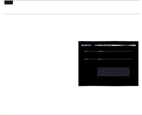
5.After entering the POST screen, the BIO-FLASHER
utility pops out. Choose <fs0> to search for the BIOS file.
Chapter 3: UEFI BIOS & Software | 17
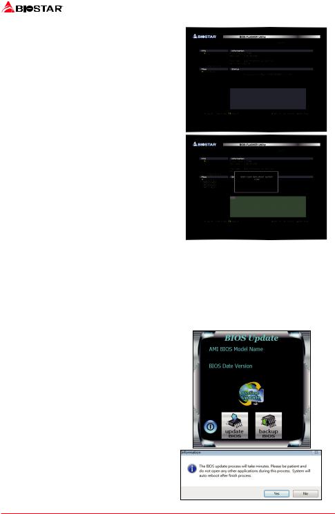
6. Select the proper BIOS file, and a message asking if you are sure to flash the BIOS file. Click “Yes” to start updating BIOS.
7.A dialog pops out after BIOS flash is completed, asking you to restart the system. Press the <Y> key to restart system.
8.While the system boots up and the full screen logo shows up, press <DEL> key to enter BIOS setup.
After entering the BIOS setup, please go to the <Save & Exit>, using the <Restore Defaults> function to load Optimized Defaults, and select <Save Changes and Reset> to restart the computer. Then the BIOS Update is completed.
BIOS Update Utility (through the Internet)
1.Installing BIOS Update Utility from the DVD Driver.
2.Please make sure the system is connected to the internet before using this function.
3.Launch BIOS Update Utility and click the
“Online Update” button on the main screen.
4. An open dialog will show up to request your agreement to start the BIOS update. Click “Yes” to start the online update procedure.
18 | Chapter 3: UEFI BIOS & Software

H410MH / H410MHP 
5.If there is a new BIOS version, the utility will ask you to download it. Click “Yes” to proceed.
6.After the download is completed, you will be asked to program (update) the BIOS or not. Click “Yes” to proceed.
7.After the updating process is finished, you will be asked you to reboot the system. Click
“OK” to reboot.
8.While the system boots up and the full screen logo shows up, press <DEL> key to enter BIOS setup.
After entering the BIOS setup, please go to the <Save & Exit>, using the <Restore Defaults> function to load Optimized Defaults, and select <Save Changes> and <Reset> to restart the computer. Then, the BIOS Update is completed.
BIOS Update Utility (through a BIOS file)
1.Installing BIOS Update Utility from the DVD Driver.
2.Download the proper BIOS from http://www.biostar.com.tw/
3.Launch BIOS Update Utility and click the “Update
BIOS” button on the main screen.
4. A warning message will show up to request your agreement to start the BIOS update. Click “OK” to start the update procedure.
Chapter 3: UEFI BIOS & Software | 19
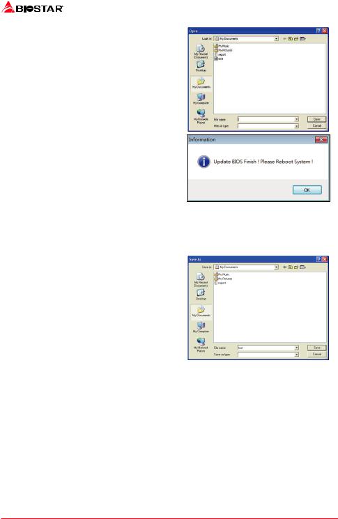
5.Choose the location for your BIOS file in the system. Please select the proper BIOS file, and then click on “Open”. It will take several minutes, please be patient.
6.After the BIOS Update process is finished, click on “OK” to reboot the system.
7.While the system boots up and the full screen logo shows up, press <DEL> key to enter BIOS setup.
After entering the BIOS setup, please go to the <Save & Exit>, using the <Restore Defaults> function to load Optimized Defaults, and select <Save Changes and Reset> to restart the computer. Then, the BIOS Update is completed.
Backup BIOS
Click the Backup BIOS button on the main screen for the backup of BIOS, and select a proper location for your backup BIOS file in the system, and click “Save”.
20 | Chapter 3: UEFI BIOS & Software
H410MH / H410MHP 
3.3 Software
Installing Software
1.Insert the Setup DVD to the optical drive. The driver installation program would appear if the Auto-run function has been enabled.
2.Select Software Installation, and then click on the respective software title.
3.Follow the on-screen instructions to complete the installation.
Launching Software
After the installation process is completed, you will see the software icon showing on the desktop. Double-click the icon to launch it.
 Note
Note
» All the information and content about following software are subject to be changed without notice.
For better performance, the software is being continuously updated.
» The information and pictures described below are for your reference only. The actual information
and settings on board may be slightly different from this manual.
BIOScreen Utility
This utility allows you to personalize your boot logo easily. You can choose BMP as your boot logo so as to customize your computer.
Please follow the step-by-step instructions below to update boot logo: • Load Image: Choose the picture as the boot logo.
• Transform: Transform the picture for BIOS and preview the result.
• Update Bios: Write the picture to BIOS Memory to complete the update.
Chapter 3: UEFI BIOS & Software | 21

Chapter 4: Useful help
4.1Driver Installation
After you installed your operating system, please insert the Fully Setup Driver DVD into your optical drive and install the driver for better system performance.
You will see the following window after you insert the DVD
The setup guide will auto detect your motherboard and operating system.
A. Driver Installation
To install the driver, please click on the Driver icon. The setup guide will list the compatible driver for your motherboard and operating system. Click on each device driver to launch the installation program.
B. Software Installation
To install the software, please click on the Software icon. The setup guide will list the software available for your system, click on each software title to launch the installation program.
C. Manual
Aside from the paperback manual, we also provide manual in the Driver DVD. Click on the
Manual icon to browse for available manual.
 Note
Note
» If this window didn’t show up after you insert the Driver DVD, please use file browser to locate and
execute the file SETUP.EXE under your optical drive.
» You will need Acrobat Reader to open the manual file. Please download the latest version of Acrobat
Reader software from http://get.adobe.com/reader/
»» The motherboard used in the illustrations may not resemble the actual board. these illustrations are
for reference only.
22 | Chapter 4: Useful help

H410MH / H410MHP 
4.2AMI BIOS Beep Code
Boot Block Beep Codes
Number of Beeps |
Description |
Continuing |
Memory sizing error or Memory module not found |
POST BIOS Beep Codes
Number of Beeps |
Description |
1 |
Success booting. |
8 |
Display memory error (system video adapter) |
4.3AMI BIOS post code
Code |
Description |
10 |
PEI Core is started |
11 |
Pre-memory CPU initialization is started |
15 |
Pre-memory North Bridge initialization is started |
19 |
Pre-memory South Bridge initialization is started |
2B |
Memory initialization. Serial Presence Detect (SPD) data reading |
2C |
Memory initialization. Memory presence detection |
2D |
Memory initialization. Programming memory timing information |
2E |
Memory initialization. Configuring memory |
2F |
Memory initialization (other). |
31 |
Memory Installed |
32 |
CPU post-memory initialization is started |
33 |
CPU post-memory initialization. Cache initialization |
34 |
CPU post-memory initialization. Application Processor(s) (AP) initialization |
35 |
CPU post-memory initialization. Boot Strap Processor (BSP) selection |
36 |
CPU post-memory initialization. System Management Mode (SMM) initialization |
37 |
Post-Memory North Bridge initialization is started |
3B |
Post-Memory North Bridge initialization (North Bridge module specific) |
4F |
DXE IPL is started |
60 |
DXE Core is started |
F0 |
Recovery condition triggered by firmware (Auto recovery) |
F1 |
Recovery condition triggered by user (Forced recovery) |
F2 |
Recovery process started |
F3 |
Recovery firmware image is found |
F4 |
Recovery firmware image is loaded |
E0 |
S3 Resume is stared (S3 Resume PPI is called by the DXE IPL) |
E1 |
S3 Boot Script execution |
E2 |
Video repost |
E3 |
OS S3 wake vector call |
60 |
DXE Core is started |
61 |
NVRAM initialization |
62 |
Installation of the South Bridge Runtime Services |
63 |
CPU DXE initialization is started |
68 |
PCI host bridge initialization |
69 |
North Bridge DXE initialization is started |
6A |
North Bridge DXE SMM initialization is started |
Chapter 4: Useful help | 23

|
|
|
|
|
|
Code |
Description |
|
70 |
South Bridge DXE initialization is started |
|
71 |
South Bridge DXE SMM initialization is started |
|
72 |
South Bridge devices initialization |
|
78 |
South Bridge DXE Initialization (South Bridge module specific) |
|
79 |
ACPI module initialization |
|
90 |
Boot Device Selection (BDS) phase is started |
|
91 |
Driver connecting is started |
|
92 |
PCI Bus initialization is started |
|
93 |
PCI Bus Hot Plug Controller Initialization |
|
94 |
PCI Bus Enumeration |
|
95 |
PCI Bus Request Resources |
|
96 |
PCI Bus Assign Resources |
|
97 |
Console Output devices connect |
|
98 |
Console input devices connect |
|
99 |
Super IO Initialization |
|
9A |
USB initialization is started |
|
9B |
USB Reset |
|
9C |
USB Detect |
|
9D |
USB Enable |
|
A0 |
IDE initialization is started |
|
A1 |
IDE Reset |
|
A2 |
IDE Detect |
|
A3 |
IDE Enable |
|
A4 |
SCSI initialization is started |
|
A5 |
SCSI Reset |
|
A6 |
SCSI Detect |
|
A7 |
SCSI Enable |
|
A8 |
Setup Verifying Password |
|
A9 |
Start of Setup |
|
AB |
Setup Input Wait |
|
AD |
Ready To Boot event |
|
AE |
Legacy Boot event |
|
AF |
Exit Boot Services event |
|
B0 |
Runtime Set Virtual Address MAP Begin |
|
B1 |
Runtime Set Virtual Address MAP End |
|
B2 |
Legacy Option ROM Initialization |
|
B3 |
System Reset |
|
B4 |
USB hot plug |
|
B5 |
PCI bus hot plug |
|
B6 |
Clean-up of NVRAM |
|
B7 |
Configuration Reset (reset of NVRAM settings) |
|
24 | Chapter 4: Useful help

|
|
H410MH / H410MHP |
|
4.4Troubleshooting |
|
|
|
|
|
|
|
Probable |
Solution |
|
|
1. There is no power in the system. Power LED does |
1. Make sure power cable is securely plugged in. |
|
|
not shine; the fan of the power supply does not work |
2. |
Replace cable. |
|
2. Indicator light on keyboard does not shine. |
3. |
Contact technical support. |
|
|
|
|
|
System is inoperative. Keyboard lights are on, power |
Using even pressure on both ends of the DIMM, |
|
|
indicator lights are lit, and hard drives are running. |
press down firmly until the module snaps into place. |
|
|
|
|
|
|
|
1. |
Check cable running from disk to disk controller |
|
|
board. Make sure both ends are securely plugged in; |
|
|
System does not boot from a hard disk drive, but can |
check the drive type in the standard CMOS setup. |
|
|
be booted from optical drive. |
2. |
Backing up the hard drive is extremely important. |
|
|
All hard disks are capable of breaking down at any |
|
|
|
time. |
|
|
|
|
|
|
System only boots from an optical drive. Hard disks |
1. |
Back up data and applications files. |
|
can be read, applications can be used, but system |
2. |
Reformat the hard drive. Re-install applications |
|
fails to boot from a hard disk. |
and data using backup disks. |
|
|
|
|
|
|
Screen message shows “Invalid Configuration” or |
Review system’s equipment. Make sure correct |
|
|
“CMOS Failure.” |
information is in setup. |
|
|
|
|
|
|
|
1. |
Set master/slave jumpers correctly. |
|
System cannot boot after user installs a second hard |
2. |
Run SETUP program and select correct drive types. |
|
drive. |
Call the drive manufacturers for compatibility with |
|
|
|
other drives. |
|
|
|
|
|
|
CPU Overheated
If the system shutdown automatically after power on system for seconds, that means the CPU protection function has been activated.
When the CPU is over heated, the motherboard will shutdown automatically to avoid a damage of the CPU, and the system may not power on again.
In this case, please double check:
1.The CPU cooler surface is placed evenly with the CPU surface.
2.CPU fan is rotated normally.
3.CPU fan speed is fulfilling with the CPU speed.
After confirmed, please follow steps below to relief the CPU protection function.
1.Remove the power cord from power supply for seconds.
2.Wait for seconds.
3.Plug in the power cord and boot up the system.
Or you can:
1.Clear the CMOS data. (See “Close CMOS Header: JCMOS1” section)
2.Wait for seconds.
3.Power on the system again.
Chapter 4: Useful help | 25

APPENDIX I: Specifications in Other Languages
Arabic
(10 ﻞ ﻴﺠﻟا) Intel® Core / Pentium / Celeron ىد مإ ﻪﻳا ﺞﻟﺎﻌﻤﻟ 1200 ﺬﺧﺄﻤﻟا |
|
||||||
ﻂﻘﻓ 400 ﺔﺌﻓ ﺮﺷﺎﻌﻟا ﻞﻴﺠﻟا ﻦﻣ Intel® Core ™ تﺎﺠﻟﺎﻌﻤﻟا ﺔﻠﺋﺎﻋ ﻢﻋﺪﺗ |
* |
ﺔﻳﺰآﺮﻤﻟا ﺔﺠﻟﺎﻌﻤﻟا ةﺪﺣو ةﺪﻋﺎﻗ |
|||||
.CPU ﺞﻟﺎﻌﻤﻟا ﻢﻋد ﺔﻤﺋﺎﻘﻟ |
www.biostar.com.tw ﻊﻗﻮﻤﻟا ﻰﻟإ عﻮﺟﺮﻟا ﻰﺟﺮﻳ |
* |
|
||||
|
|
INTEL® H410 |
ﺢﺋاﺮﺸﻟا ﺔﻋﻮﻤﺠﻣ |
||||
1866/ 2133/ 2400/ 2666/ 2933 DDR4 .را .يد .يد ﺔﺟودﺰﻣ ةﺎﻨﻗ ﻢﻋﺪﺗ |
|
||||||
ةﺮآاذ ﺖﻳﺎﺑﺎﺠﻴﺟ 64 ﻰﺼﻗأ ﺪﺤآ ﻞﻤﺤﺘﺗ ،DIMM ﺔﺟودﺰﻤﻟا ةﺮآاﺬﻟا تﺎﺤﺘﻓ |
DDR4 .را .يد .يد 2x |
ةﺮآاﺬﻟا |
|||||
DDR4 را .يد .يد ﺖﻳﺎﺑﺎﺠﻴﺟ 32/16/8/4 ECC نود ﻞﻤﺤﺘﺗ |
DIMM ﺔﺟودﺰﻣ ﺔﺤﺘﻓ ﻞآ |
||||||
|
|||||||
.ةﺮآاﺬﻟا ﻢﻋد ﺔﻤﺋﺎﻘﻟ |
www.biostar.com.tw ﻊﻗﻮﻤﻟا ﻰﻟإ عﻮﺟﺮﻟا ﻰﺟﺮﻳ |
* |
|
||||
|
(6Gb/s) SATA III ﺎﺗﺎﺳ 4x ﺔﻠﺻو |
|
|||||
:(ﻂﻘﻓ H410MH ﻢﻋد ) ﺀﺎﺑﺮﻬآ ﺲﺑﺎﻗ (M Key) M.2 ﺔﺤﺘﻓ X1 |
|
||||||
|
SSD 2280 /2260 /2242 Type M.2 ﻢﻋﺪ ﺗ |
ﻦﻳﺰﺨﺘﻟا |
|||||
SSD (6Gb/s) SATA III & (10Gb/s) 2× 2.0 PCI-E ﻢﻋﺪ ﺗ |
|
||||||
. SATA_1 ﻞﺻﻮﻣ ﻞﻴﻄﻌﺗ ﻢﺘﻴﺳ ، PCIE-M2_1 ﺔﺤﺘﻓ ﻰﻠﻋ SATA SSD ةﺪﺣو ماﺪﺨﺘﺳا ﺪﻨﻋ * |
|
||||||
|
|
RTL8111H |
LAN ﺔﻴﻠﺤﻣ ﺔﻜﺒﺷ |
||||
ﺔﺟودﺰﻤﻟا ىﻮﺼﻘﻟا ةرﺪﻘﻟا / ﻒﺼﻨﻟا ، ﻲﺋﺎﻘﻠﺗ ﺪﻳﺪﺤﺗ ، ﺔﻴﻧﺎﺜﻟا / ﺖﻳﺎﺑﺎﺠﻴﻣ 1000 / 100 / 10 |
|||||||
|
|||||||
|
|
|
ALC887 |
ﻲﺗﻮﺼﻟا ﺰﻴﻣﺮﺘﻟا |
|||
|
|
ﺔﻗﺪﻟا ﺔﻴﻟﺎﻋ تاﻮﻨﻗ 7.1 |
|||||
|
|
|
|||||
( ﻲﻠﺧاﺪﻟا عزﻮﻤﻟا لﻼﺧ ﻦﻣ 2 و ﺔﻴﻔﻠﺨﻟا جرﺎﺨﻤﻟاو ﻞﺧاﺪﻤﻟا ﻲﻓ 2) (Gen1) 3.2 USB مﺎﻋ ﻞﺴﻠﺴﺘﻣ ﻞﻗﺎﻧ x 4 ﺬﻓﺎﻨﻣ |
USB مﺎﻋ ﻞﺴﻠﺴﺘﻣ ﻞﻗﺎﻧ |
||||||
( ﻲﻠﺧاﺪﻟا عزﻮﻤﻟا لﻼﺧ ﻦﻣ 2و ﺔﻴﻔﻠﺨﻟا جرﺎﺨﻤﻟاو ﻞﺧاﺪﻤﻟا ﻲﻓ 4) 2.0 USB مﺎﻋ ﻞﺴﻠﺴﺘﻣ ﻞﻗﺎﻧ x 6 ﺬﻓﺎﻨﻣ |
|||||||
|
|||||||
|
|
|
|
||||
|
1 x 2.0 PCIe ﺔﻴﻓﺎﺿﻹا تﺎﻘﺤﻠﻤﻟا ﺬﻔﻨﻣ |
ﺔﺤﺘﻓ x 2 |
ﻊﺳﻮﺘﻟا تﺎﺤﺘﻓ |
||||
|
16 x 3.0 PCIe ﺔﻴﻓﺎﺿﻹا تﺎﻘﺤﻠﻤﻟا ﺬﻔﻨﻣ |
ﺔﺤﺘﻓ x 1 |
|||||
|
|
||||||
|
|
ةرﺎﻔﻟا |
PS/2 x 1 |
|
|||
|
ﺮﺗﻮﻴﺒﻤﻜﻠﻟ ﺢﻴﺗﺎﻔﻤﻟا ﺔﺣﻮﻟ |
PS/2 x 1 |
|
||||
|
HDMI ﺔﻴﻤﻗر ﺔﻴﺋﺮﻣ ﺔﻬﺟاو x 1 دﺪﻋ ﻞﻴﺻﻮﺗ ﺔﺤﺘﻓ |
|
|||||
|
VGA ﺔﻴﻤﻗر ﺔﻴﺋﺮﻣ ﺔﻬﺟاو x 1 دﺪﻋ ﻞﻴﺻﻮﺗ ﺔﺤﺘﻓ |
ﺔﻴﻔﻠﺨﻟا جرﺎﺨﻤﻟاو ﻞﺧاﺪﻤﻟا |
|||||
(Gen1) 3.2 USB مﺎﻋ ﻞﺴﻠﺴﺘﻣ ﻞﻗﺎﻧ x 2 دﺪﻋ ﻞﻴﺻﻮﺗ ﺔﺤﺘﻓ |
|||||||
|
|||||||
|
2.0 USB مﺎﻋ ﻞﺴﻠﺴﺘﻣ ﻞﻗﺎﻧ x 4 دﺪﻋ ﻞﻴﺻﻮﺗ ﺔﺤﺘﻓ |
|
|||||
|
LAN ﺔﻴﻠﺤﻤﻟا ﺔﻜﺒﺸﻟا x 1 دﺪﻋ ﻞﻴﺻﻮﺘﻟ ﺔﺤﺘﻓ |
|
|||||
|
تﻮﺼﻠﻟ كﺎﺟ x 3 دﺪﻋ ﻞﻴﺻﻮﺗ ﺔﺤﺘﻓ |
|
|||||
|
SATA III (6Gb/s) ﺎﺗﺎﺳ |
4x ﺔﻠﺻو |
|
||||
(2.0 USB مﺎﻋ ﻞﺴﻠﺴﺘﻣ ﻞﻗﺎﻧ ﻦﻴﺘﺤﺘﻓ ﻞﻤﺤﺘﻳ عزﻮﻣ ﻞآ ) 2.0 USB مﺎﻋ ﻞﺴﻠﺴﺘﻣ ﻞﻗﺎﻧ |
x 1 عزﻮﻣ |
|
|||||
((Gen1)3.2 USB مﺎﻋ ﻞﺴﻠﺴﺘﻣ ﻞﻗﺎﻧ ﻦﻴﺘﺤﺘﻓ ﻞﻤﺤﺘﻳ عزﻮﻣ ﻞآ ) (Gen1) 3.2 USB مﺎﻋ ﻞﺴﻠﺴﺘﻣ ﻞﻗﺎﻧ |
x 1 عزﻮﻣ |
|
|||||
|
|
ﺲﻴﺑﺎﺑد 8 x 1 ﺔﻗﺎﻄﻠﻟ ﺔﻠﺻو |
|
||||
|
سﻮﺑد 24 x 1 ﺔﻗﺎﻄﻠﻟ ﺔﻠﺻو |
|
|||||
|
ﺔﻳﺰآﺮﻤﻟا ﺔﺠﻟﺎﻌﻤﻟا ةﺪﺣو ﺪﻳﺮﺒﺗ ﺔﺣوﺮﻣ |
|
x 1 ﺔﻠﺻو |
ﺔﻴﻠﺧاﺪﻟا جرﺎﺨﻤﻟاو ﻞﺧاﺪﻤﻟا |
|||
|
ﺔﻣﻮﻈﻨﻤﻟا ﺪﻳﺮﺒﺗ حواﺮﻣ |
|
x 1 ﺔﻠﺻو |
|
|||
|
|
ﺔﻴﻣﺎﻣﻷا ﺔﺣﻮﻠﻟا |
|
x 1 عزﻮﻣ |
|
||
|
|
ﻲﻣﺎﻣﻷا تﻮﺼﻟا |
|
x 1 عزﻮﻣ |
|
||
|
|
ﺮﺷﺎﺒﻣ سﻮﻤﻴﺳ |
|
x 1 عزﻮﻣ |
|
||
|
|
ﺔﻴﻠﺴﻠﺴﺗ ﺔﺤﺘﻓ |
|
x 1 عزﻮﻣ |
|
||
ﻢﻣ 226 x ﻢﻣ 179 ، uATX ﺔﻣﺪﻘﺘﻤﻟا ﺎﻴﺟﻮﻟﻮﻨﻜﺘﻟا دﺪﻣ ﻞﻜﺷ ﻞﻣﺎﻋ |
ﻞﻜﺸﻟا ﻞﻣﺎﻋ |
||||||
|
|
10(64bit)زوﺪﻨﻳو |
|
ﺔﻣﻮﻋﺪﻤﻟا ﻞﻴﻐﺸﺘﻟا ﺔﻤﻈﻧأ |
|||
.رﺎﻈﻧأ نوﺪﺑ وأ ﻊﻣ ﻞﻴﻐﺸﺗ مﺎﻈﻧ يﻷ ﻢﻋﺪﻟا ﺔﻟزأ وأ ﺔﻓﺎﺿإ ﻖﺤﺑ ﻆﻔﺘﺤﺗ BIOSTAR رﺎﺘﺳﻮﻴﺑ * |
|||||||
|
|||||||
26 | APPENDIX I: Specifications in Other Languages
 Loading...