


MCP6P3/N68S3 BIOS Manual
BIOS Setup ................................................................................................. |
1 |
1 Main Menu............................................................................................... |
3 |
2Advanced Menu....................................................................................... |
7 |
3 PCIPnP Menu........................................................................................ |
18 |
4 Boot Menu.............................................................................................. |
22 |
5 Chipset Menu......................................................................................... |
24 |
6 Performance Menu............................................................................... |
29 |
7 Exit Menu............................................................................................... |
34 |
i

MCP6P3/N68S3 BIOS Manual
BIOS Setup
Introduction
The purpose of this manual is to describe the settings in the AMI BIOS Setup program on this motherboard. The Setup program allows users to modify the basic system configuration and save these settings to CMOS RAM. The power of CMOS RAM is supplied by a battery so that it retains the Setup information when the power is turned off.
Basic Input-Output System (BIOS) determines what a computer can do without accessing programs from a disk. This system controls most of the input and output
devices such as keyboard, mouse, serial ports and disk drives. BIOS activates at the first stage of the booting process, loading and executing the operating system. Some additional features, such as virus and password prot ection or chipset fine-tuning options are also included in BIOS.
The rest of this manual will to guide you through the options and settings in BIOS Setup.
Plug and Play Support
This AMI BIOS supports the Plug and Play Version 1.0A specification.
EPA Green PC Support
This AMI BIOS supports Version 1.03 of the EPA Green PC specification.
APM Support
This AMI BIOS supports Version 1.1&1.2 of the Advanced Power Management (APM) speci fication. Power management features are implemented via the System
Management Int errupt (SMI). Sleep and Suspend power management modes are supported. Power to the hard disk drives and video monitors can also be managed by this AMI BIOS.
ACPI Support
AMI ACPI BIOS support Version 1.0/2.0 of Advanced Configuration and Power interface specifi cation (ACPI). It provides ASL code for power management and device configuration capabilities as defined in the ACPI specification, developed by Microsoft, Intel and Toshiba.
1
MCP6P3/N68S3 BIOS Manual
PCI Bus Support
This AMI BIOS also supports Version 2.3 of the Intel PCI (Peripheral Component Interconnect) local bus speci fication.
DRAM Support
DDR3 SDRAM (Double Data Rate III Synchronous DRAM) is supported.
Supported CPUs
This AMI BIOS supports the AMD CPU.
Using Setup
When starting up the computer, press
<Del> during the Power-On Self-Test
(POST) to enter the BIOS setup utility. In the BIOS setup utility, you will see
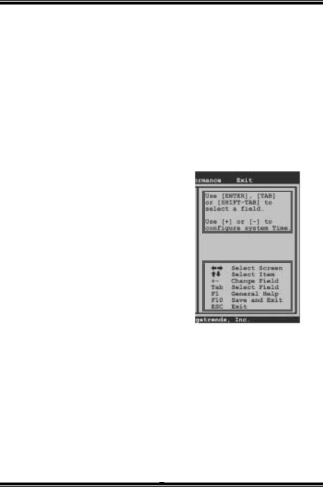
General Help description at the top right corner, and this is providing a brief description of the selected item. Navigation Keys for that particular menu are at the bottom right corner, and you can use these keys to select item and change the settings.
Notice
General Help
Navigation Keys
zThe default BIOS settings apply for most conditions to ensure optimum performance of the motherboard. If the system becomes unstable after changing any settings, please load the default settings to ensure system’s compatibility and stability. Use
Load Setup Default under the Exit Menu.
z For better system perform ance, the BIOS firmware is being continuously updated. The BIOS information described in this manual is for your reference only. The actual BIOS information and settings on board may be slightly different from this manual.
zThe content of this manual is subject to be changed without notice. We will not be responsible for any mistakes found in this user’s manual and any system damage that may be caused by wrong-settings.
2

MCP6P3/N68S3 BIOS Manual
1 Main Menu
Once you enter AMI BIOS Setup Utility, the Main Menu will appear on the screen providing an overview of the basic system inform ation.
|
|
|
|
|
|
|
BIOS S ETUP UTILITY |
|
|
|
|
|
|
|
Main |
|
Advanced |
PCIPnP |
Boot |
Chips et |
Perfo rmance |
Exit |
|||||
|
|
|
|
|
|
|
|
|
|
|
|
|
|
|
|
Syste m Overview |
|
|
|
|
|
|
Use [ENTER], [TA B] |
||||
|
|
AMI B IOS |
|
|
|
|
|
|
|
or [ SHIFT-TAB] t o |
|||
|
|
:01.01.0 1 |
|
|
|
|
|
sele ct a field. |
|||||
|
|
Versi on |
|
|
|
|
|
Use [+] or [-] t o |
|||||
|
|
Build |
Date:01/01/0 9 |
|
|
|
|
|
|||||
|
|
Syste m Memory |
|
|
|
|
|
|
conf igure system Time. |
||||
|
|
Size |
|
: |
|
|
|
|
|
|
|
|
|
|
|
Syste m Time |
|
[00:00:00] |
|
|
|
|
|
||||
|
|
Syste m Date |
|
[Thu 01/01/2009] |
|
|
|
|
S elect Screen |
||||
|
|
Flopp y A |
|
|
|
|
|
|
|
|
|||
|
|
|
|
|
|
|
|
|
+- |
S elect Item |
|||
|
|
> IDE |
Configuratio n |
|
|
|
|
|
C hange Field |
||||
|
|
|
|
|
|
|
Ta b |
S elect Field |
|||||
|
|
|
|
|
|
|
|
|
|
|
|
F1 |
G eneral Help |
|
|
|
|
|
|
|
|
|
|
|
|
F1 0 |
S ave and Exit |
|
|
|
|
|
|
|
|
|
|
|
|
ES C |
E xit |
vxx.xx (C)C opyright 198 5-200x, Amer ican Megatre nds, Inc.
AMI BIOS
Shows system information including BIOS version and built date.
System Memory
Shows system memory size, VGA shard memory will be excluded..
System Time
Set the system internal clock.
System Date
Set the system date. Note that the ‘Day’ automatically changes when you set the date.
Floppy A
Select the type of floppy disk drive installed in your system.
Options: 360K, 5.25 in / 1.2M, 5.25 in / 720K, 3.5 in / 1.44M, 3.5 in / 2.88M, 3.5 in / None
3
MCP6P3/N68S3 BIOS Manual
IDE Configuration
The BIOS will automatically detect the presence of IDE/SATA devices. There is a sub-menu for each IDE/SATA device. Select a device and press <Enter> to enter the sub-menu of detailed options.
BIOS S ETUP UTILITY
Main
IDE C onfiguration
OnBoa rd IDE Contro ller |
[ Enabled] |
||
Serai l-ATA Devices |
[ Device 0/1] |
||
> nVi dia |
RAID Setu p |
|
|
> Pri mary IDE Mast er |
|
||
> Pri mary IDE Slav e |
|
||
> SAT A 1 |
Device |
|
|
> SAT A 2 |
Device |
|
|
> SAT A 3 |
Device |
|
|
> SAT A 4 |
Device |
|
|
Hard Disk Write |
Pr otect |
[ Disabled] |
|
IDE D etect Time |
Ou t (Sec) |
[ 35] |
|
DISA BLED: disabl es the inte grated IDE
Cont roller.
ENAB LED: enables the
inte grated IDE Cont roller.
S elect Screen
S elect Item
En terG o to Sub Scr een
F1 |
G eneral Help |
|
F1 0 |
S ave |
and Exit |
ES C |
E xit |
|
vxx.xx (C)C opyright 198 5-200x, Amer ican Megatre nds, Inc.
OnBoard IDE Controller
This item allows you to control the onboard IDE controller. Options: Enhanced (Default) / Disabled
Serial-ATA Dev ices
This item allows you to choose SATA Devices.
Options: Device 0/1 (Default) / Device 0 / Disabled
4

MCP6P3/N68S3 BIOS Manual
nVidia RAID Setup
BIOS S ETUP UTILITY
Chips et
RAID |
Setup |
|
|
Options |
|
|
|
|
|
|
Disabled |
nVidi a RAID Functi on |
[ Disabled] |
|
|||
SATA |
1 |
Raid |
[ Disabled] |
|
Enab led |
SATA |
2 |
Raid |
[ Disabled] |
|
|
SATA |
3 |
Raid |
[ Disabled] |
|
|
SATA |
4 |
Raid |
[ Disabled] |
|
|
|
S elect |
Screen |
|
S elect |
Item |
En terU pdate |
|
|
F1 |
G eneral Help |
|
F1 0 |
S ave and Exit |
|
ES C |
E xit |
|
vxx.xx (C)C opyright 198 5-200x, Amer ican Megatre nds, Inc.
nVidia RAIDFunction
This item allows you to activate RAID function. Options: Disabled (Default) / Enabled
SATA 1/2/3/4 Raid
Enable or disable RAID function of SATA devices.
Options: Disabled (Default) / Enabled
Primary IDE Master/Slav e ; SATA 1/2/3/4 Device
|
|
|
|
BIOS SETUP UTILITY |
|
Main |
|
|
|
|
|
|
Primary IDE Master |
|
Select the type |
||
|
|
|
|
|
of device connected |
|
Device |
: |
|
||
|
|
to the system. |
|||
|
Type |
|
[Auto] |
||
|
LBA/Large Mode |
[Auto] |
|||
|
Block (Multi-Sector Transfer)[Auto] |
||||
|
PIO Mode |
|
[Auto] |
||
|
DMA Mode |
|
[Auto] |
||
|
S.M.A.R.T |
|
[Auto] |
||
|
32Bit Data Transfer |
[Enabled] |
|||
|
Select Screen |
+- |
Select Item |
Change Option |
|
F1 |
General Help |
F10 |
Save and Exit |
ESC |
Exit |
vxx.xx (C)Copyright 1985-200x, American Megatrends, Inc.
5

MCP6P3/N68S3 BIOS Manual
The BIOS detects the information and values of respective devices, and these information and values are shown below to the name of the sub-menu.
Type
Select the type of the IDE/SATA drive.
Options: Auto (Default) / CDROM / ARMD / Not Installed
LBA/Large Mode
Enable or disable the LBA mode.
Options: Auto (Default) / Disabled
Block (Multi-Sector Transfer)
Enable or disable multi-sector transfer.
Options: Auto (Default) / Disabled
PIO Mode
Select the PIO mode.
Options: Auto (Default) / 0 / 1 / 2 / 3 / 4
DMA Mode
Select the DMA mode.
Options: Auto (Default) / SWDMA0 ~ 2 / MWDMA0 ~ 2 / UDMA0 ~ 5
S.M.A.R.T
Set the Smart Monitoring, Analysis, and Reporting Technology.
Options: Auto (Default) / Disabled / Enabled
32Bit Data Transfer
Enable or disable 32-bit data transfer. Options: Enabled (Default) / Disabled
Hard Disk Write Protect
Disable or enable device write protection. This will be effective only if the device is accessed through BIOS.
Options: Disabled (Default) / Enabled
IDE Detect Time Out (Sec)
Select the time out value for detecting IDE/SATA devices.
Options: 35 (Default) / 30 / 25 / 20 / 15 / 10 / 5 / 0
6

MCP6P3/N68S3 BIOS Manual
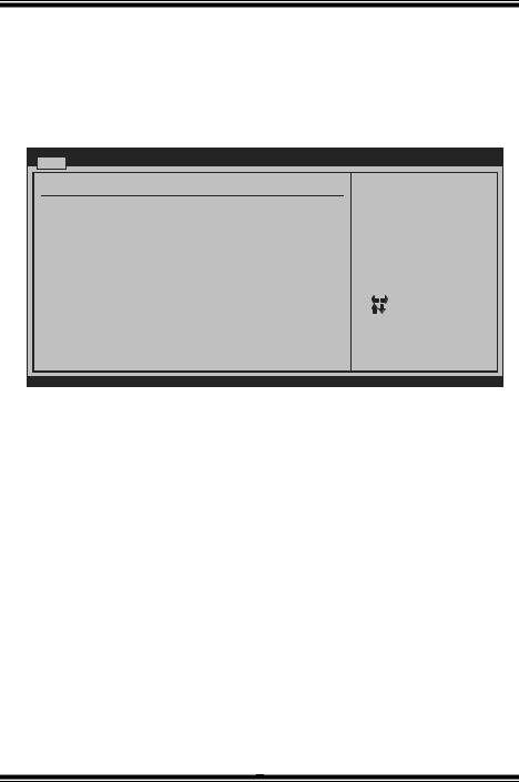
2 Advanced Menu
The Advanced Menu allows you to configure the settings of CPU, Super I/O, Power Management, and other system devices.
Notice
zBeware of that setting inappropriate values in items of this menu may cause system to malfunction.
|
|
|
|
|
|
BIOS |
S ETUP UTILITY |
|
|
Exit |
Main |
Advanced |
|
PCIPnP |
Boot |
Chips et |
Perfo rmance |
||||
|
Advan ced |
Settings |
|
|
|
|
Conf igure CPU. |
|||
|
WARNI NG: Setting w rong values in |
below sec tions |
|
|||||||
|
|
|
may cause |
system to m alfunction. |
|
|
|
|||
>CPU Configuratio n
>Sup erIO Configur ation
> Har dware Health Configuratio n > Sma rt Fan Config uration
>Pow er Configurat ion
>USB Configuratio n
S elect Screen
S elect Item
En terG o to Sub Scr een
F1 G eneral Help
F1 0 |
S ave |
and Exit |
ES C |
E xit |
|
vxx.xx (C)C opyright 198 5-200x, Amer ican Megatre nds, Inc.
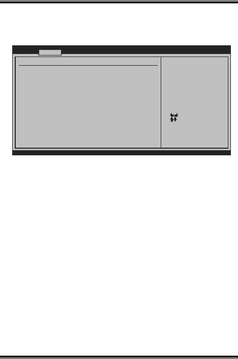
CPU Configuration
This item shows the CPU information that the BIOS automatically detects.
BIOS S ETUP UTILITY
Advanced
CPU C onfiguration
Modul e Version:
AGESA |
Version: |
|
Physi cal Count: |
|
|
Logic al Count: |
|
|
AMD C PU |
|
|
Revis ion: |
|
|
Cache |
L1: |
|
Cache |
L2: |
|
Cache |
L3: |
NB Clk: |
Speed |
: |
|
ncHT |
Speed : |
Width I/O : |
Able |
to Change Fre q |
: |
uCode |
Patch Level |
: |
GART |
Error Reporti ng |
[ Disabled] |
Micro code Update |
[ Enabled] |
|
Secur e Virtual Mac hine Mode |
[ Enabled] |
Power Now |
[ Enabled] |
This option shou ld rema in disabled for
the normal opera tion. The driver devel oper
may enable it fo r test ing purpose.
|
S elect Screen |
+- |
S elect Item |
C hange Option |
|
F1 |
G eneral Help |
F1 0 |
S ave and Exit |
ES C |
E xit |
vxx.xx (C)C opyright 198 5-200x, Amer ican Megatre nds, Inc.
7

MCP6P3/N68S3 BIOS Manual
GART Error Reporting
This option should remain disabled for the normal operation. The driver eveloper may enable it for testing purpose.
Options: Disabled (Default) / Enabled
Microcode Update
This item allows you to enable or disable Microcode Update function. Options: Enabled (Default) / Disabled
Secure Virtual Machine Mode
Virtualization Technology can virtually separate your system resource into several parts, thus enhance the performance when running virtual machines or multi interface systems.
Options: Enabled (Default) / Disabled
PowerNow
This item allows you to enable or disable the PowerNow power saving technology. Options: Enabled (Default) / Disabled
ACPI SRAT Table
The operating system scans the ACPI SRAT at boot time and uses the information to better allocate memory and schedule software threads for maximum perform ance. This item controls whether the SRAT is made available to the operating system at boot up, or not.
Options: Enabled (Default) / Disabled
Probe Filter
This item allows you to control the initialization mode for Probe Filter. Options: Auto (Default) / Disabled / MP Mode
8

MCP6P3/N68S3 BIOS Manual
SuperIO Configuration
BIOS S ETUP UTILITY
Advanced
|
Confi gure ITE8718 Super IO Chi pset |
|
Allo ws BIOS to E nable |
|||
|
|
|
|
|
or D isable Flopp y |
|
|
Onboa rd Floppy Con troller |
[ Enabled] |
|
|||
|
|
Cont roller |
||||
|
Seria l Port1 Addre ss |
[ 3F8/IRQ4] |
|
|
|
|
|
Paral lel Port Addr ess |
[ 378] |
|
|
|
|
|
Par allel Port Mo de |
[ Normal] |
|
|
|
|
|
Par allel Port IR Q |
[ IRQ7] |
|
|
|
|
|
Keybo ard PowerOn |
[ Disabled] |
|
|
|
|
|
Mouse PowerOn |
[ Disabled] |
|
|
|
|
|
Resto re on AC Powe r Loss |
[ Power Off] |
|
|
|
|
|
|
|
|
|
|
S elect Screen |
|
|
|
|
|
+- |
S elect Item |
|
|
|
|
|
C hange Option |
|
|
|
|
|
|
F1 |
G eneral Help |
|
|
|
|
|
F1 0 |
S ave and Exit |
|
|
|
|
|
ES C |
E xit |
|
|
|
|
|
|
|
vxx.xx (C)C opyright 198 5-200x, Amer ican Megatre nds, Inc.
Onboard Floppy Controller
Select enabled if your system has a floppy disk controller (FDC) installed on the system board and you wish to use it. If you installed another FDC or the system uses no floppy drive, select disabled in this field.
Options: Enabled (Default) / Disabled
Serial Port1 Address
Select an address and corresponding interrupt for the first and second seri al ports. Options: 3F8/IRQ4 (Default) / 2F8/IRQ3 / 3E8/IRQ4 / 2E8/IRQ3 / Disabled
Parallel Port Address
This item allows you to determine access onboard parallel port controller with which I/O Address.
Options: 378 (Default) / 278 / 3BC / Disabled
Parallel Port Mode
This item allows you to determine how the parallel port should function.
Options: Normal (Default) |
Using Parallel port as Standard Printer Port. |
EPP |
Using Parallel Port as Enhanced Parallel Port. |
ECP |
Using Parallel port as Extended Capabilities Port. |
ECP+EPP |
Using Parallel port as ECP & EPP mode. |
|
|
|
|
|
9 |
MCP6P3/N68S3 BIOS Manual
ECP Mode DMA Channel
This item allows you to select parallel port ECP DMA.
Options: DMA3 (Default) / DMA0 / DMA1
Parallel Port IRQ
This item allows you to select the IRQ for the onboard parallel port. Options: IRQ7 (Default) / IRQ5 / Disabled
Keyboard Pow erOn
This item allows you to control the keyboard power on function. Options: Disabled (Default) / Specific Key / Stroke Key / Any Key
Specific Key Enter
This item will show only when Keyboard PowerOn is set “Specific Key.”
Stroke Keys Selected
This item will show only when Keyboard PowerOn is set “Stroke Key.” Options: Ctrl+F1 (Default) / Wake Key / Power Key / Ctrl+F2 / Ctrl+F3 /
Ctrl +F4 / Ctrl+F5 / Ctrl+F6
Mouse PowerOn
This item allows you to control the mouse power on function.
Options: Disabled (Default) / Enabled
Restore on AC Power Loss
This setting specifies how your system should behave after a power fail or interrupts occurs. By choosing Disabled will leave the computer in the power off state.
Choosing Enabled will restore the system to the status before power failure or
interrupt occurs.
Options: Power Off (Default) / Last State
10
MCP6P3/N68S3 BIOS Manual
Hardware Health Configuration
This item shows the system temperature, fan speed, and voltage information.
BIOS S ETUP UTILITY
Advanced
Hardw are Health Co nfiguration
H/W H ealth Functio n |
[ Enabled] |
Shutd own Temperatu re |
[ Disabled] |
CPU T emperature |
|
CPU F AN |
|
Sytem 1 FAN |
|
CPU V core |
|
Chips et Voltage |
|
+3.30 V |
|
+5.00 V |
|
+12.0 V |
|
HT Vo ltage |
|
Memor y Voltage |
|
5V(SB ) |
|
Enab les Hardware Heal th Monitorin g Devi ce.
|
S elect Screen |
+- |
S elect Item |
C hange Option |
|
F1 |
G eneral Help |
F1 0 |
S ave and Exit |
ES C |
E xit |
vxx.xx (C)C opyright 198 5-200x, Amer ican Megatre nds, Inc.
H/W Health Function
If with a monitoring system, the system will showPC health status during POST stage. Options: Enabled (Default) / Disabled
Shutdow n Temperature
This item allows you to set up the CPU shutdown Temperature. This item is only
effective under Windows 98 ACPI mode.
Options: Disabled (Default) / 60 /140 / 65 /149 / 70 /158 / 75 /167 / 80 /176 / 85 /185 / 90 /194
11
 Loading...