


FCC Information and Copyright
This equipment has been tested and found to comply with the limits of a Class B digital device, pursuant to Part 15 of the FCC Rules. These limits are designed to provide reasonable protection against harmful interference in a residential installation. This equipment generates, uses, and can radiate radio frequency energy and, if not installed and used in accordance with the instructions, may cause harmful interference to radio communications. There is no guarantee that interference will not occur in a particular installation.
The vendor makes no representations or warranties with respect to the contents here and specially disclaims any implied warranties of merchantability or fitness for any purpose. Further the vendor reserves the right to revise this publication and to make changes to the contents here without obligation to notify any party beforehand.
Duplication of this publication, in part or in whole, is not allowed without first obtaining the vendor’s approval in writing.
The content of this user’s manual is subject to be changed without notice and we will not be responsible for any mistakes found in this user’s manual. All the brand and product names are trademarks of their respective companies.
Dichiarazione di conformità sintetica
Ai sensi dell’art. 2 comma 3 del D.M. 275 del 30/10/2002
Si dichiara che questo prodotto è conforme alle normative vigenti e soddisfa i requisiti essenziali richiesti dalle direttive
2004/108/CE, 2006/95/CE e 1999/05/CE quando ad esso applicabili
Short Declaration of conformity
We declare this product is complying with the laws in force and meeting all the essential requirements as specified by the directives
2004/108/CE, 2006/95/CE and 1999/05/CE whenever these laws may be applied

Table Of Contents
FCC Information and Copyright 1 Chapter 1: Introduction 3
1.1 Before You Start 3
1.2 Package Checklist 3
1.3 Specifications 4
1.4 Rear Panel Connectors 5
1.5 Motherboard Layout 6
Chapter 2: Hardware installation 7
2.1 Install Central Processing Unit (CPU) 7
2.2 Install a Heatsink 9
2.3 Connect Cooling Fans 10
2.4 Install System Memory 10
2.5 Expansion Slots 12
2.6 Jumper & Switch Setting 13
2.7 Headers & Connectors 14
Chapter 3: UEFI BIOS & Software 17
3.1 UEFI BIOS Setup 17
3.2 BIOS Update 17
3.3 Software 21
Chapter 4: Useful help 24
4.1 Driver Installation 24
4.2 AMI BIOS Beep Code 25
4.3 AMI BIOS post code 25
4.4 Troubleshooting 27
APPENDIX I: Specifications in Other Languages 28
Arabic 28 German 29 Russian 30 Spanish 31 Thai 32
2 | Table Of Contents

H110MHV3 / H110MGV3 / H110MLV3 
Chapter 1: Introduction
1.1 Before You Start
Thank you for choosing our product. Before you start installing the motherboard, please make sure you follow the instructions below:
• Prepare a dry and stable working environment with sufficient lighting. • Always disconnect the computer from power outlet before operation.
• Before you take the motherboard out from anti-static bag, ground yourself properly by touching any safely grounded appliance, or use grounded wrist strap to remove the static charge.
• Avoid touching the components on motherboard or the rear side of the board unless necessary. Hold the board on the edge, do not try to bend or flex the board.
• Do not leave any unfastened small parts inside the case after installation. Loose parts will cause short circuits which may damage the equipment.
• Keep the computer from dangerous area, such as heat source, humid air and water. • The operating temperatures of the computer should be 0 to 45 degrees Celsius. • To avoid injury, be careful of:
Sharp pins on headers and connectors
Rough edges and sharp corners on the chassis Damage to wires that could cause a short circuit
1.2Package Checklist
• Serial ATA Cable x2
• Rear I/O Panel for ATX Case x1 • Quick Installation Guide x1 • Fully Setup Driver DVD x1
 Note
Note
» The package contents may be different due to the sales region or models in which it was sold. For more information about the standard package in your region, please contact your dealer or sales representative.
Chapter 1: Introduction | 3

1.3 Specifications
Specifications
|
Socket 1151 for Intel® Core i7 / i5 / i3 / Pentium / Celeron processor |
|
CPU Support |
Maximum CPU TDP (Thermal Design Power): 91Watt |
|
|
* Please refer to www.biostar.com.tw for CPU support list. |
|
Chipset |
INTEL® H110 |
|
|
Supports Dual Channel DDR3L 1866(OC)/1600/1333 |
|
Memory |
2x DDR3L DIMM Memory Slot, Max. Supports up to 16 GB Memory |
|
Each DIMM supports non-ECC 4/8 GB DDR3L module |
||
|
||
|
* Please refer to www.biostar.com.tw for Memory support list. |
|
Storage |
4x SATA III Connector |
|
supports AHCI |
||
|
||
|
RTL8111H (H110MHV3, H110MGV3) |
|
LAN |
1x 10/ 100/ 1000 Mb/s auto negotiation, Half / Full duplex capability |
|
RTL8106E (H110MLV3) |
||
|
||
|
1x 10/ 100 Mb/s auto negotiation, Half / Full duplex capability |
|
Audio Codec |
ALC887 |
|
7.1 Channels, High Definition Audio |
||
|
||
USB |
4x USB 3.0 port (2 on rear I/Os and 2 via internal header) |
|
6x USB 2.0 port (2 on rear I/Os and 4 via internal header) |
||
|
||
Expansion Slots |
1x PCIe 2.0 x1 Slot |
|
1x PCIe 3.0 x16 Slot (x16) |
||
|
||
|
1x PS/2 Mouse |
|
|
1x PS/2 Keyboard |
|
|
1x HDMI Port (H110MHV3) |
|
Rear I/Os |
1x VGA Port |
|
1x LAN port |
||
|
||
|
2x USB 2.0 Port |
|
|
2x USB 3.0 Port |
|
|
3x Audio Jack |
|
|
4x SATA III Connector |
|
|
2x USB 2.0 Header |
|
|
1x USB 3.0 Header |
|
|
1x 4-Pin Power Connector |
|
|
1x 24-Pin Power Connector |
|
Internal I/Os |
1x CPU Fan Connector |
|
|
1x System Fan Connector |
|
|
1x Front Panel Header |
|
|
1x Front Audio Header |
|
|
1x Clear CMOS Header |
|
|
1x TPM Header |
|
Form Factor |
uATX Form Factor, 170mm x 190mm |
|
OS Support |
Windows 7/ 8.1(64bit)/ 10(64bit) |
|
Biostar reserves the right to add or remove support for any OS with or without notice. |
||
|
4 | Chapter 1: Introduction
H110MHV3 / H110MGV3 / H110MLV3 
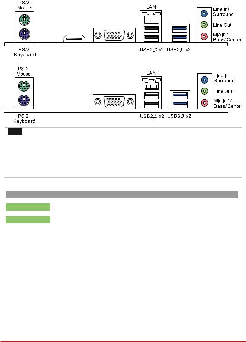
1.4Rear Panel Connectors
H110MHV3
HDMI VGA
H110MGV3 / H110MLV3
VGA
 Note
Note
» VGA & HDMI ports only work with an Intel® integrated Graphics Processor.
»»» Maximum resolution
VGA: 1920 x 1200 @60Hz
HDMI: 4096 x 2160 @24Hz, compliant with HDMI 1.4a
»»» To configure 7.1-channel audio, you have to use a chassis with HD front panel audio module and
enable the multi-channel audio feature through O.S. Audio Utility.
The 2/ 4/ 5.1/ 7.1-channel configuration
Audio Port |
2-channel |
4-channel |
5.1 channel |
7.1 channel |
Blue (Rear Panel) |
Line In |
Line In |
Line In |
Side Speaker Out |
Green (Rear Panel) |
Line Out |
Front Speaker Out |
Front Speaker Out |
Front Speaker Out |
Pink (Rear Panel) |
Mic In |
Mic In |
Center/Subwoofer Out |
Center/Subwoofer Out |
Green (Front Panel) |
Headphone |
Rear Speaker Out |
Rear Speaker Out |
Rear Speaker Out |
Chapter 1: Introduction | 5

1.5 Motherboard Layout
 Note
Note
»  represents the 1st pin.
6 | Chapter 1: Introduction
H110MHV3 / H110MGV3 / H110MLV3 
Chapter 2: Hardware installation
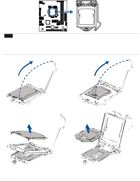
2.1 Install Central Processing Unit (CPU)
Step 1: Locate the CPU socket on the motherboard
 Note
Note
» Remove pin cap before installation, and make good preservation for future use. When the CPU is
removed, cover the pin cap on the empty socket to ensure pin legs won’t be damaged.
» The motherboard might equip with two different types of pin cap. Please refer below instruction to
remove the pin cap.
Step 2: Pull the socket locking lever out from the socket and then raise the lever up.
Step 3: Remove the Pin Cap.
Chapter 2: Hardware installation | 7
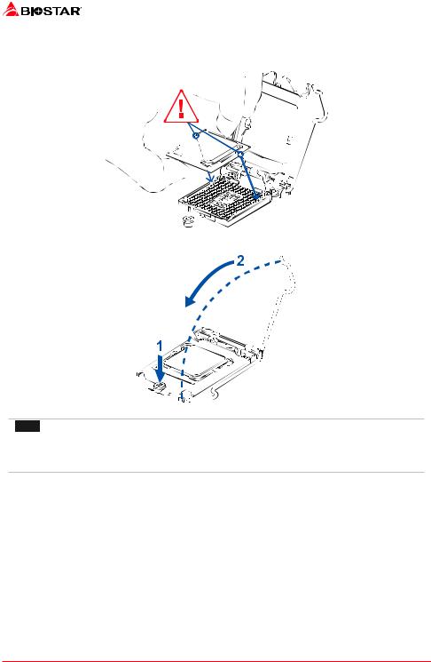
Step 4: Hold processor with your thumb and index fingers, oriented as shown. Align the notches with the socket. Lower the processor straight down without tilting or sliding the processor in the socket.
Step 5: Hold the CPU down firmly, and then lower the lever to locked position to complete the installation.
 Note
Note
» Ensure that you install the correct CPU designed for LGA1151 socket.
» The CPU fits only in one correct orientation. Do not force the CPU into the socket to prevent
damaging the CPU.
8 | Chapter 2: Hardware installation
H110MHV3 / H110MGV3 / H110MLV3 
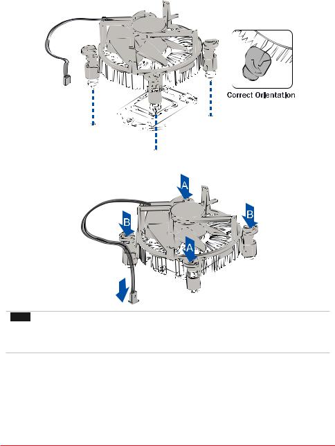
2.2 Install a Heatsink
Step 1: Place the CPU fan assembly on top of the installed CPU and make sure that the four fasteners match the motherboard holes. Orient the assembly and make the fan cable is closest to the CPU fan connector.
Step 2: Press down two fasteners at one time in a diagonal sequence to secure the CPU fan assembly in place. As each fastener locks into position a click should be heard.
 Note
Note
» Apply the thermal interface material on the CPU before heatsink installation, if necessary.
» Do not forget to connect the CPU fan connector.
» For proper installation, please kindly refer to the installation manual of your CPU heatsink.
Chapter 2: Hardware installation | 9
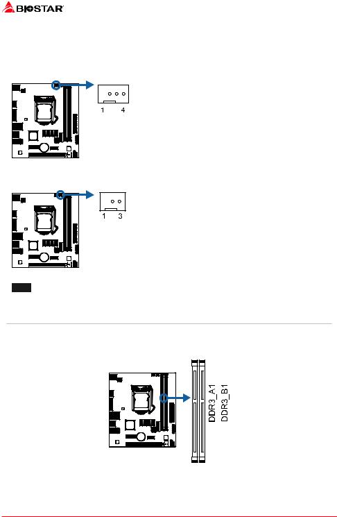
2.3 Connect Cooling Fans
These fan headers support cooling-fans built in the computer. The fan cable and connector may be different according to the fan manufacturer.
CPU_FAN1: CPU Fan Header
|
|
|
|
|
|
|
|
|
|
|
|
|
|
|
|
|
|
|
|
|
|
|
|
|
|
|
|
|
|
|
|
|
|
|
|
|
|
|
|
|
|
|
|
|
|
|
|
|
|
Pin |
Assignment |
|
|
|
|
|
|
|
|
|
|
|
|
|
|
1 |
Ground |
||||||||||
|
|
||||||||||||||||||||||||
|
|
|
|
|
|
|
|
|
|
|
|
|
|
|
|
|
|
|
|
|
|
|
|
|
|
|
|
|
|
|
|
|
|
|
|
|
|
|
|
|
|
|
|
|
|
|
|
|
|
|
|
|
|
|
|
|
|
|
|
|
|
|
|
|
|
|
|
|
|
|
|
|
|
2 |
+12V |
||
|
|
|
|
|
|
|
|
|
|
|
|
|
|
|
|
|
|
|
|
|
|
|
|
3 |
FAN RPM rate sense |
|
|
|
|
|
|
|
|
|
|
|
|
|
|
|
|
|
|
|
|
|
4 |
Smart Fan Control (By Fan) |
|||
|
|
|
|
|
|
|
|
|
|
|
|
|
|
|
|
|
|
|
|
|
|
|
|
|
|
|
|
|
|
|
|
|
|
|
|
|
|
|
|
|
|
|
|
|
|
|
|
|
|
|
|
SYS_FAN1: System Fan Header
|
|
|
|
|
|
|
|
|
|
|
|
|
|
|
|
|
|
|
|
|
|
|
|
|
|
|
|
|
|
|
|
|
|
|
|
|
|
|
|
|
|
|
|
|
|
|
|
|
|
|
|
|
|
|
|
|
|
|
|
|
|
|
|
|
|
|
|
|
|
|
|
|
|
|
|
|
|
Pin |
Assignment |
|
|
|
|
|
|
|
|
|
|
|
|
|
|
|
|
|
|
|
|
|
|
1 |
Ground |
|
|||
|
|
|
|
|
|
|
|
|
|
|
|
|
|
|
|
|
|
|
|
|
||||||
|
|
|
|
|
|
|
|
|
|
|
|
|
|
|
|
|
|
|
|
|
|
2 |
+12V |
|
||
|
|
|
|
|
|
|
|
|
|
|
|
|
|
|
|
|
|
|
|
|
|
3 |
FAN RPM rate sense |
|
||
|
|
|
|
|
|
|
|
|
|
|
|
|
|
|
|
|
|
|
|
|
|
|
|
|
|
|
|
|
|
|
|
|
|
|
|
|
|
|
|
|
|
|
|
|
|
|
|
|
|
|
|
|
|
|
|
|
|
|
|
|
|
|
|
|
|
|
|
|
|
|
|
|
|
|
|
|
|
|
|
|
|
|
|
|
|
|
|
|
|
|
|
|
|
|
|
|
|
|
|
|
|
|
|
|
|
|
|
 Note
Note
» CPU_FAN1, SYS_FAN1 support 4-pin and 3-pin head connectors. When connecting with wires onto connectors, please note that the red wire is the positive and should be connected to pin#2, and the black wire is Ground and should be connected to pin#1(GND).
2.4 Install System Memory
DDR3L Modules
10 | Chapter 2: Hardware installation
 Loading...