


865G Micro 775

865G Mirco 775 / 865GV Micro 775
Setup Manual
FCC Inf or m at ion and Copyright
This equipment has been tested and found to comply with the limits of a Class
B digital device, pursuant to Part 15 of the FCC Rules . These limits are designed
to p rovide reasonable protec tion against ha rmful int erfere nce in a residential
installation. This equipment generates , uses and can radiate radio frequency
energy and, if not ins talled and used in accordance with the instructions, may
cause harmful interference to radio communications. There is no guarantee
that i nterfere nce will not occur in a partic ular ins ta lla tion.
The vendor makes no representations o r wa rran ties wi th respec t to t he
contents here and specially disclaims any implied warranties of merchantability
o r fitnes s fo r a ny purpos e . F urthe r t he ve ndor res e rves the ri g ht to rev ise t h is
publication and to make changes to the c ontents here without obligation to
notify any party beforehand.
D uplica ti on of this publication, i n part o r in whol e , is no t allowed witho ut first
obtaining the vendor’s approval in writing.
The content of this user’s manual is subject to be changed without notice and
we will not be responsible for any mis takes found in this user’s manual. All the
brand and product names are trademarks of their respec tive companies.

Table of Con tents
Chapter 1: Introduction .............................................1
1.1 Before You Start...................................................................1
1.2 Package Checklist................................................................1
1.3 Motherboard Features..........................................................2
1.4 Rear Pan el Connectors.......................................................... 3
1.5 Mo t he r bo ar d Layou t o f 86 5G Micro 77 5..................................4
1.6 Mo t he r boa r d La yo u t o f 86 5GV Mi cro 775................................5
Chapter 2: Hardware Installation.............................. 6
2.1 Installing Ce ntral Processing Unit (CPU)................................ 6
2.2 FAN He aders........................................................................ 8
2.3 Installing Sy stem Me mo ry......................................................9
2.4 Co n nectors a nd Slo ts............................................................10
Chapter 3: Headers & Jumpers Setup......................13
3.1 How to Setup Jum per s..........................................................13
3.2 De t ail Settin gs.....................................................................13
Chapter 5: Useful Help ..............................................19
5.1 Dr i ve r Insta llat ion Note.......................................................19
5.2 Award BIO S Beep Code ........................................................20
5.3 Extra Inf ormation................................................................20
5.4 Troubl eshooting ...................................................................22
Chapter 6: WarpSpeeder™ .......................................23
6.1 Introduction........................................................................23
6.2 System Requirement............................................................23
6.3 Installation.........................................................................24
6.4 WarpSpeeder™ ....................................................................25
Appendencies: SPEC In Other Language ................31
German ................................................................................................31
France..................................................................................................33
Italian..................................................................................................35
Spanish ................................................................................................37
Portuguese...........................................................................................39
Polish...................................................................................................41
RUSSIAN...............................................................................................43
ARABIC................................................................................................45
JAPANESE............................................................................................47

865G Micro 775 & 865GV Micro 775
CHAPTER 1: INTRODUCTION
1.1 B
EFORE YOU START
Tha nk yo u fo r choosing our product. Before you start installing the
motherboard, plea se make sure you follo w the ins tru ctions below:
Prepare a dry and stable working environment with
s ufficie nt ligh ting .
Always disconnect the computer from power outlet
be fore ope ra tion .
Befo re you take the m o the rboa rd ou t f ro m a n ti-s ta tic
bag, ground yourself properly by touching any safely
grounde d appliance, or use g rounded wrist strap to
remove the static charge.
Avo id tou ch ing the com pone nt s o n mothe rbo a rd o r the
rea r side of the board unless necessa ry. Hold the bo ard
on the edge , do no t try to be nd o r flex the boa rd.
Do not lea ve any un fas tene d small pa rts inside the
case after installation. Loose parts will cause short
circuits which ma y damage the equipment.
Keep the computer from dangerous area, such as heat
source , humid a ir and wa te r.
1.2 PACKAGE CHECKLIST
FDD Cable X 1
HDD Cable X 1
Rear I/O Panel for ATX Case X 1
User’s Manua l X 1
Fully Setup Driver CD X 1
Se ria l ATA Cable X 1 (optiona l)
Se ria l ATA Po we r Cab le X 1 (o ptio nal)
USB 2.0 Cable X1 (optional)
S/P DI F ou t Cable X 1 (op tiona l)
1
Motherboard Manual
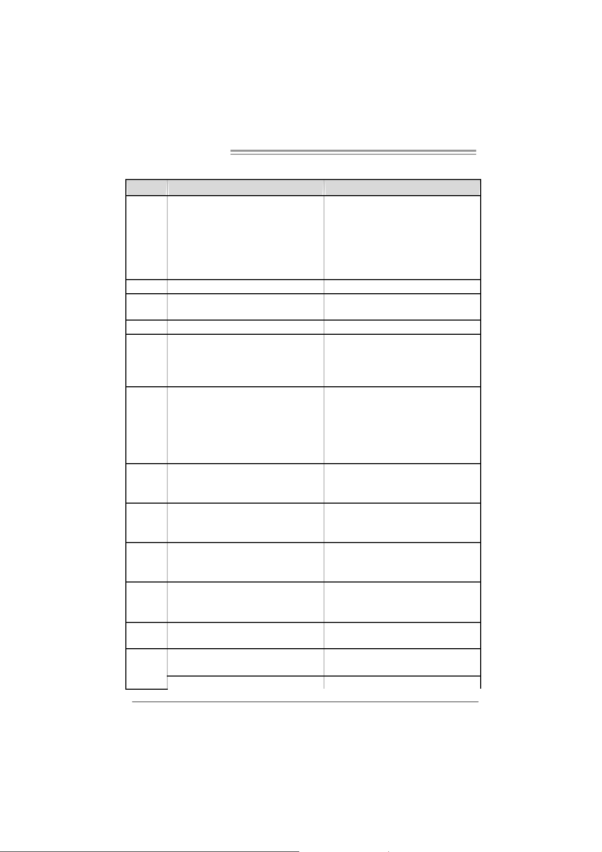
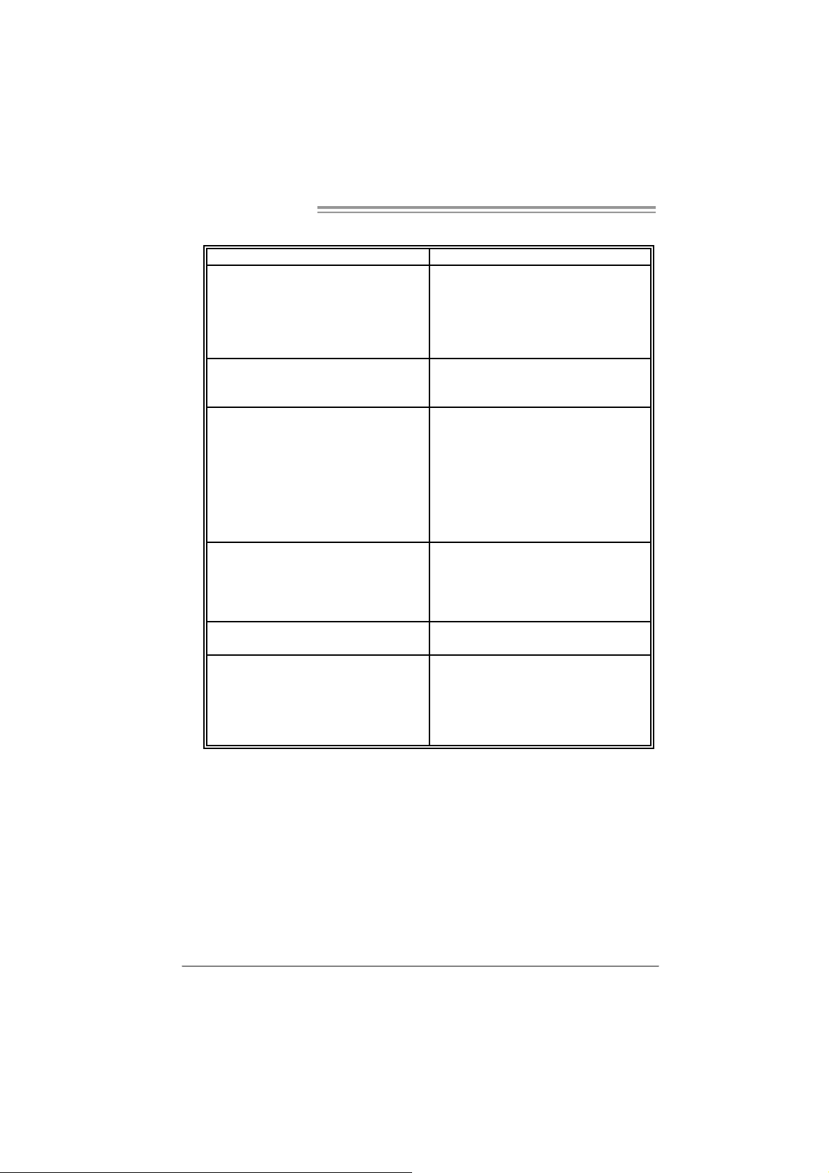
1.3 MOTHERBOARD FEATURES
865 G Micr o 775 865 GV Micr o 775
LGA 775
Intel Pentium 4 / Pentium D / Celeron D
processor up to 3.4 GHz
Supports Hyper-Threading
Execute Disable Bit
Enhanced Intel SpeedS tep
Extended Mem ory 64 Technology
Int el 865GV
Intel ICH5
ITE I T8712F
H/W Monitor
Fan Speed Controller
ITE's "Smart Guardian" funct ion
DIMM Slots x 2
Eac h DIMM supports 128/256/512MB & 1GB
DDR
Max Memory Capicity 2GB
Dual Channel Mode DDR memory module
Supports DDR 266 / 333 / 400
Integrated IDE Controller
Ultra DM A 33~100 Bus Mast er Mode
supports PIO Mode 0~4,
Integrated Serial ATA Controller
Data transfer rates up to 1.5 Gb/s.
SATA V ersion 1.0 specificat ion compliant.
Realtek RTL 8100C
10 / 100 Mb/s auto negoti ation
Half / Full duplex capability
ALC655 / 658
6 channels audio out
AC’97 Vers ion 2.3
CPU
FSB
Chipset
Graphics
Super I/O
Main
Memory
IDE
SA TA
10/100 LAN
Sound
Codec
Slots
On Board
Connector
2
LGA 775
Intel Pentium 4 / Pentium D / Celeron D
processor up to 3.4 GHz
Supports Hyper-Threading
Execute Disable Bit
Enhanced Intel SpeedS tep
Extended Mem ory 64 Technology
533 / 800 MHz 533 / 800 MHz
Int el 865G
Intel ICH5
Intel Extreme Graphics 2 Intel Extreme Graphics 2
ITE I T8712F
H/W Monitor
Fan Speed Controller
ITE's "Smart Guardian" funct ion
DIMM Slots x 2
Eac h DIMM supports 128/256/512MB & 1GB
DDR
Max Memory Capicity 2GB
Dual Channel Mode DDR memory module
Supports DDR 266 / 333 / 400
Integrated IDE Controller
Ultra DM A 33~100 Bus Mast er Mode
supports PIO Mode 0~4,
Integrated Serial ATA Controller
Data transfer rates up to 1.5 Gb/s.
SATA V ersion 1.0 specificat ion compliant.
Realtek RTL 8100C
10 / 100 Mb/s auto negoti ation
Half / Full duplex capability
ALC655 / 658
6 channels audio out
AC’97 Vers ion 2.3
AGP 8X graphics slot x1 XGP graphics slot x1
PCI s lot x3 PCI s lot x3
Fl oppy c onnecto r x1 Fl oppy c onnect or x1
IDE C onnect or x2 IDE Connector x2
SA TA Co nnect or x2 SATA Connect or x 2

865G Micro 775 & 865GV Micro 775
865 G Micr o 775 865 GV Micr o 775
Front Panel Connector x1 Front Panel Connector x1
Front Audio Connector x1 Front A udio Connector x1
CD- in C onnec tor x1 C D-i n Connector x1
S/PDIF in connector (optional) x1 S/PDIF in connector (optional) x1
S/PDIF out connector x1 S/PDIF out connector x1
CP U Fa n header x1 C PU F an header x1
Sys tem F an header x1 S ystem Fan hea der x1
Chassis open header (optional) x1 Chassis open header (optional) x1
Clear CMOS header x1 Clear CMOS header x1
USB connector x2 US B c onnector x2
Power Connector (20pin) x1 Power Connector (20pin) x1
Power Connector (4pin) x1 Power Connector (4pin) x1
PS/2 Keyboard x1
PS/2 Mouse x1
S e ri a l P ort x 1
Printer Port x1
VGA port x1
LAN port x1
USB Port x4
Audio Jack x3
Wi ndows 2000 / XP
Biostar Reserves the right to add or remove
support for any OS with or without notice.
Back Panel
I/O
Board Size
OS S upport
PS/2 Keyboard x1
PS/2 Mouse x1
S e ri a l P ort x 1
Printer Port x1
VGA port x1
LAN port x1
USB Port x4
Audio Jack x3
215 (W) x 235 (L) mm 215 (W) x 235 (L) mm
Wi ndows 2000 / XP
Biostar Reserves the right to add or remove
support for any OS with or without notice.
1.4 REAR PANEL CONNECTORS
PS/2
Mouse
PS/ 2
Keyboard
COM 1 USBX2USBX2
Printer Port
(op ti ona l)
VGA1
LAN
Line In/
Surround
Line Out
Mic In 1/
Bass/ Center
3
Motherboard Manual
A
_
(op
)
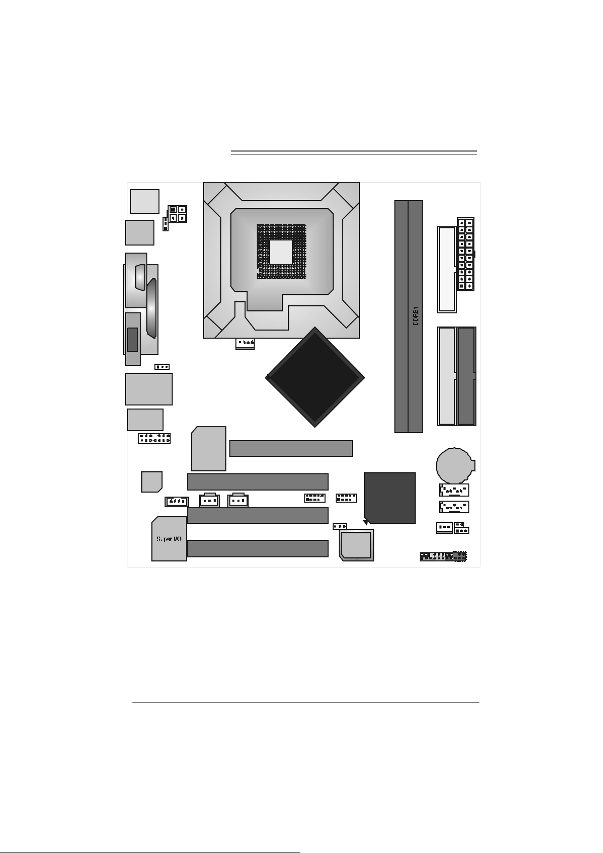
1.5 MOTHERBOARD LAYOUT OF 865G MICRO 775
JKBMS1
JATX PW R2
LGA775
JUSB1
JKB_ US BV1
(optional)
CPU1
C
JCOM1
O
M
1
JPRNT1
JATXPWR1
FD D1
JVGA1
JUSBLAN1
JA UD IO 1
JAUDIO2
Codec
JUSB V2
(optional)
(Optional)
JSPDIF_ IN1
JCDIN1
Note: represents the 1■
LAN
JCFAN1
PCI1
JS PDIF _OU T1
PC I2
PC I3
GP1
st
pin.
Intel
865G
JUSB3JUSB2
JUSBV3
tional
4
BIO S
ICH5
DDRA 1
IDE2
IDE1
BAT1
SATA2
SATA1
JCI1
JSFAN1
JCMOS1
JPA NEL1
IR (op t io nal)
4

865G Micro 775 & 865GV Micro 775
1.6 MOTHERBOARD LAYOUT OF 865GV MICRO 775
JKBMS1
JATX PW R2
JATXPWR1
FD D1
JUSB1
COM1
JCOM1
LGA775
CPU1
JPRNT1
JVGA1
JUSBLAN1
JA UD IO 1
JAUDIO2
Code c
(Optional)
JSPDIF_ IN1
JCDIN1
Note: represents the 1■
LAN
JCFAN1
PCI1
JS PDIF _OU T1
PC I2
PC I3
XGP1
st
pin.
Intel
865GV
DDRA 1
IDE2
IDE1
BAT1
JUSB3JUSB2
ICH5
SATA2
SATA1
JSFAN1
JCI1
JCMOS1
BIO S
JPA NEL1
IR (op t io nal)
5
Motherboard Manual
CHAPTER 2: HARDW ARE INSTALLATION
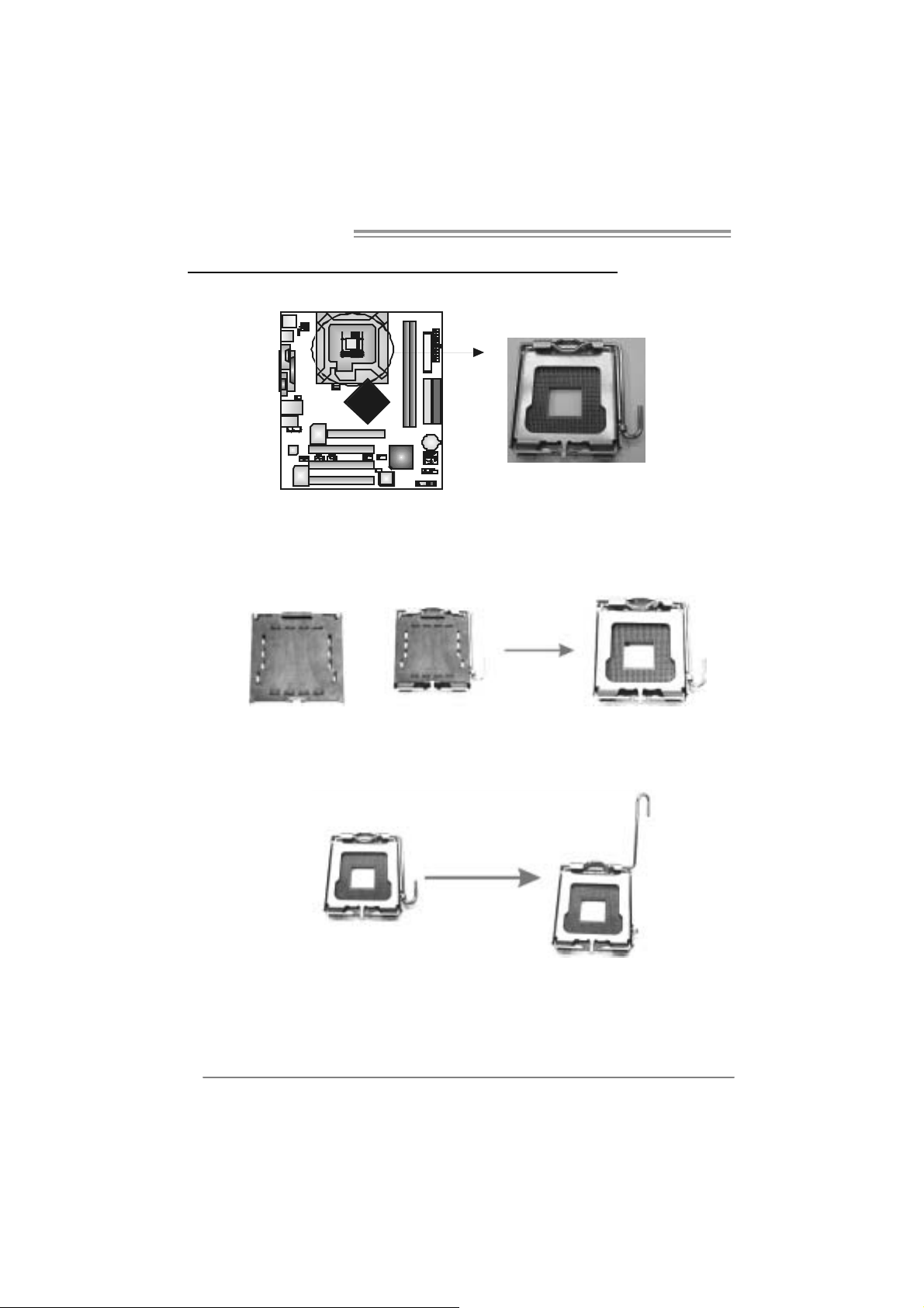
2.1 INSTALLING CENTRAL PROCESSING UNI T (CPU)
Special Notice:
Remo v e Pin Cap before installa tion, and m ake goo d preservation
for future use. When the CPU is remo ved, cov er the Pin Cap on the
empty so cket to ensure pin legs won’ t be da mag ed.
Pin Cap
Step 1: Pull the socket locking lever out from the socket and then raise
the lever up to a 90-degree angle.
6
865G Micro 775 & 865GV Micro 775
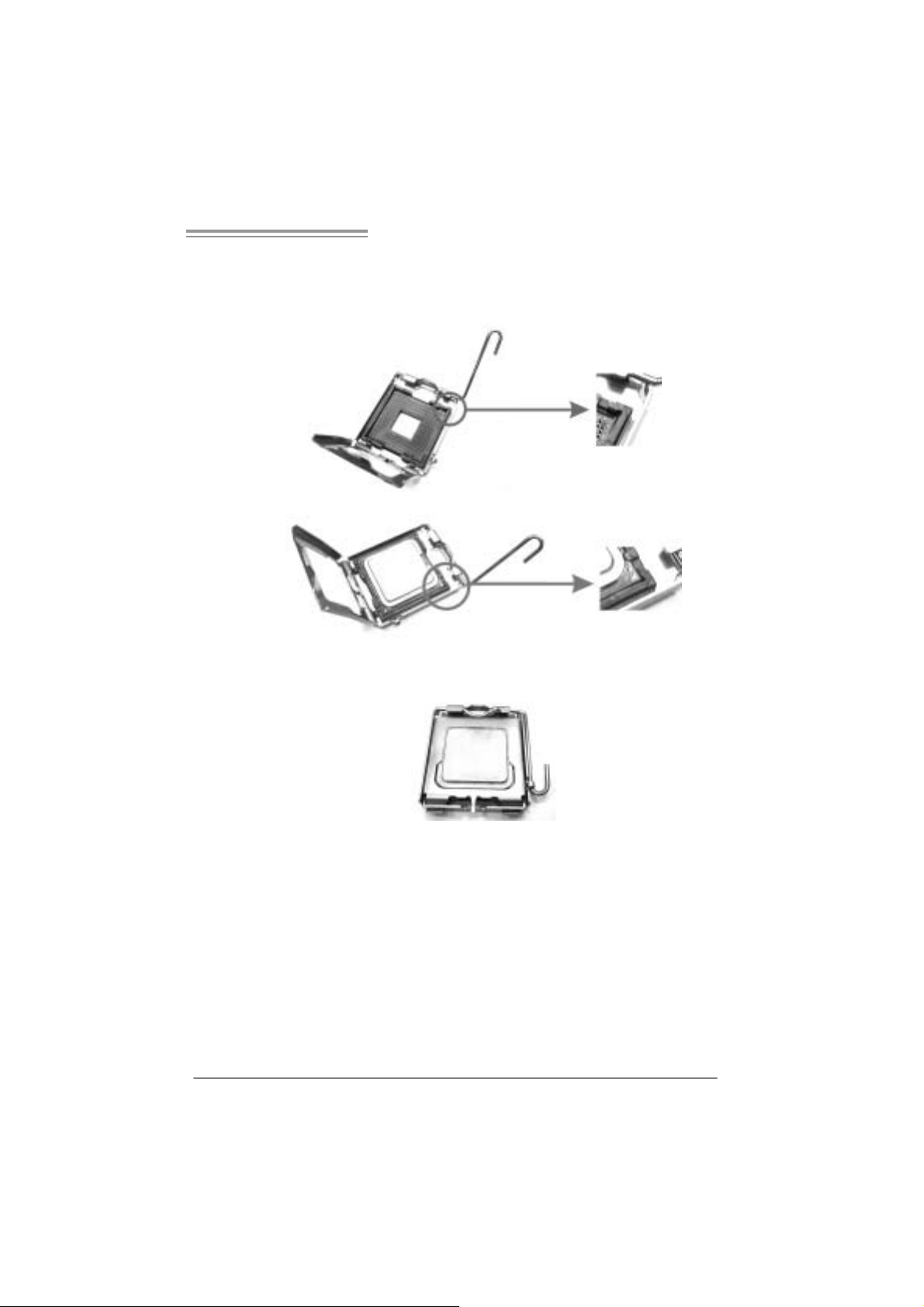
Step 2: Look for the triangular cut edge on socket, and the golden dot on
CPU should point forwards this tri angular cut edge. The CPU will
fit onl y in the correct orientation.
Step 2-1:
Step 2-2:
Step 3: Hold the CPU down firml y, and then lower the lever to locked
positi on to complete the installatio n.
Step 4: Put the CPU Fan and heatsink assem bly on the CPU and buckle it
on the retention fram e. Connect the CPU FAN power cable into
the JCFA N1. This comple te s the install a tion .
7
Motherboard Manual
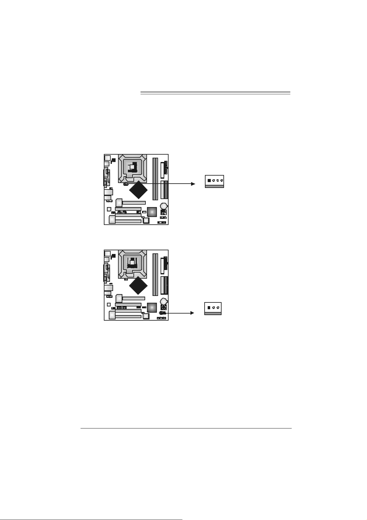
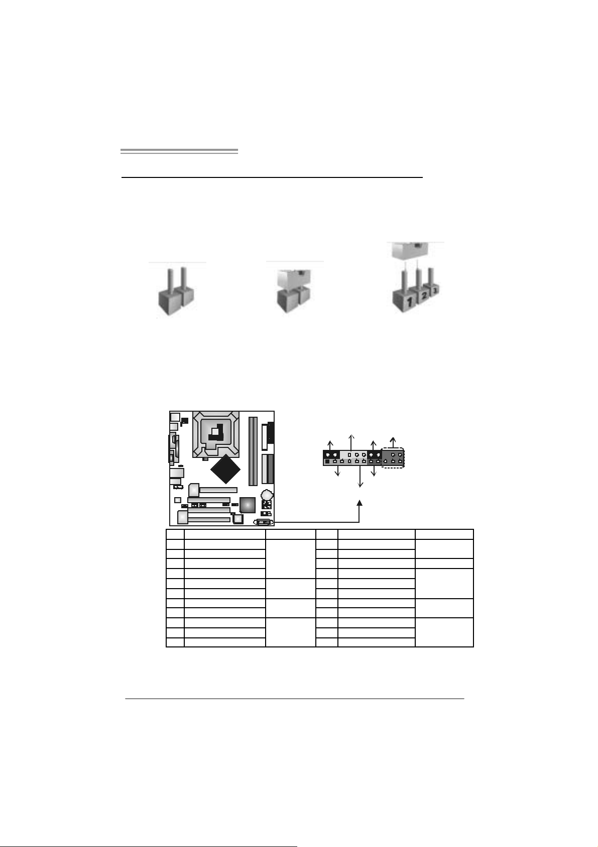
2.2 FAN HEADERS
These fan headers support cooling-fans built i n the com puter. The fan
cable and connector may be different according to the fan manufacturer.
Connect the fan cable to the connector while m atching the black wire to
pin#1.
JCFAN1: CPU Fan Header
14
JCFAN1
JSF AN1 : Sy stem Fan H eader
13
Pin
Assignment
1 Ground
2 +12V
3
FAN RPM rate
sense
4 Smart Fan
Control
Pin
Assignment
1 Ground
2 +12V
3 FAN RPM rate
sense
JSFAN1
Note:
The JSFAN1 support 3-pin head connector. When connecting with wires onto connectors,
please note that the red wire is the positi ve and should be connected to pin#2, and the
black wire is Ground and should be c onnected to GND.
8
865G Micro 775 & 865GV Micro 775
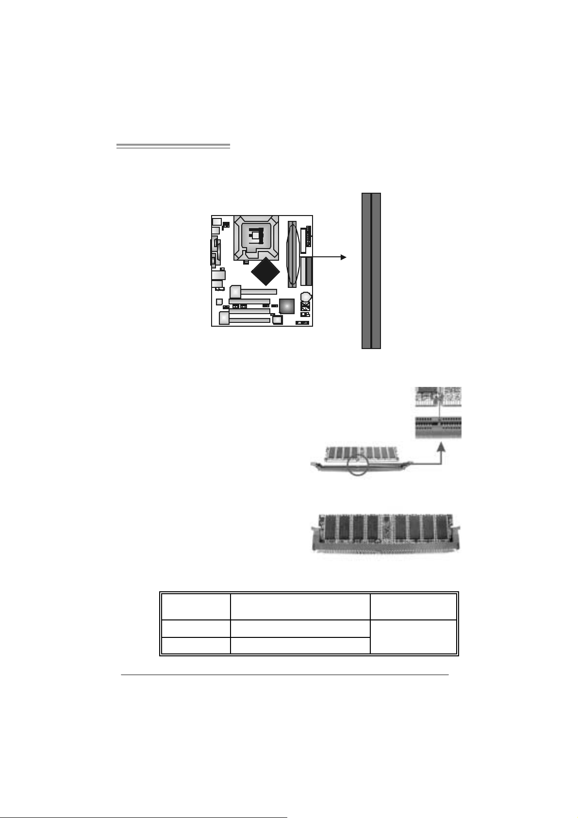
2.3 INSTALLING SYSTEM MEMORY
A. Me mo ry Modu le s
DDRB1
DDRA1
1. Unl ock a DIMM slot by pressi ng the retaining clips outward. Align a
DIMM on the slot such that the notch on the DIMM matches the
break on the Slot.
2. Insert the DIMM vertically and fi rmly into the slot until the retaining
chip snap back in place and the DIM M is properly seated.
B. Memory Capacity
DI MM Socket
Location
DDRA1 256MB/512MB/1GB *1
DDRB1 256MB/512MB/1GB *1
DDR Module Total Memory Size
Max i s 2G B.
9
Motherboard Manual
2.4 CONNECTORS AND SLOTS
FDD1: Floppy Disk Connector
The motherboard provides a st andard f loppy disk c onnector that supports 360K,
720K, 1. 2M, 1.44M and 2.88M floppy disk types . This c onnector support s the
provided f loppy driv e ribbon cables .
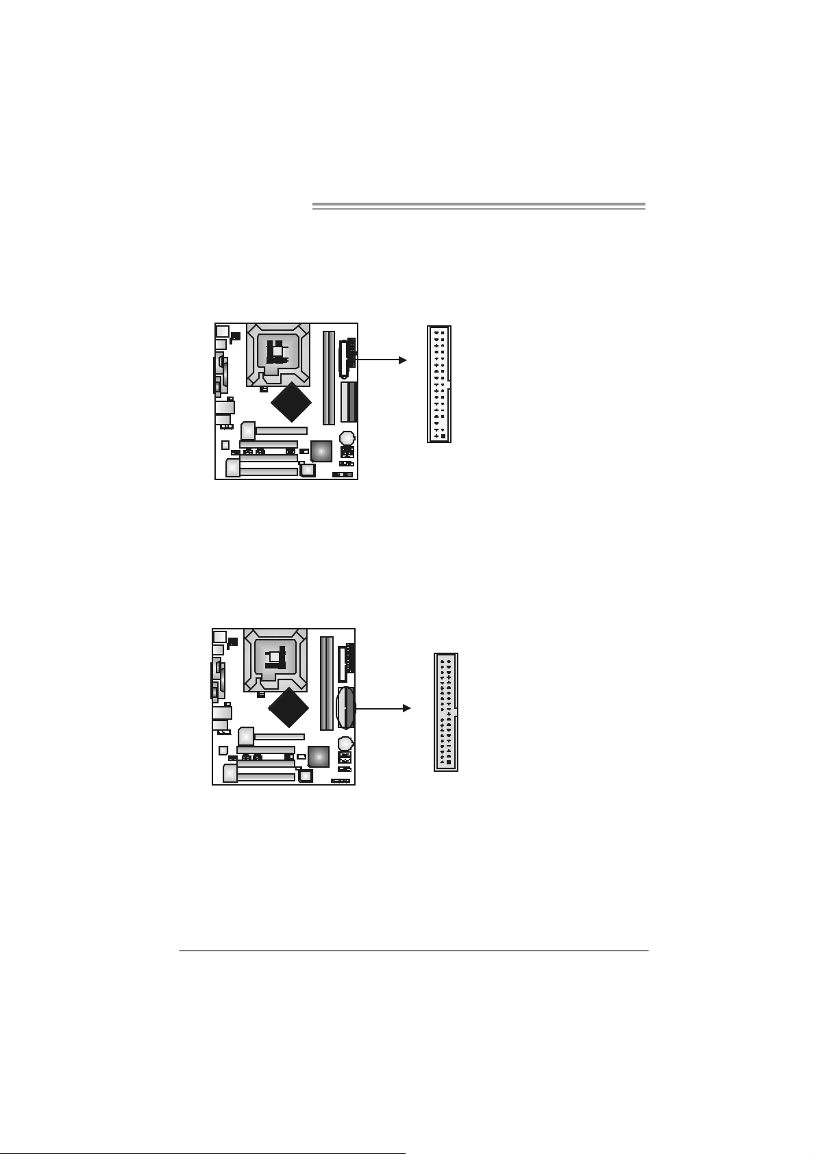
IDE1/IDE2: Ha rd Di sk Connectors
The motherboard has a 32-bit Enhanced PCI IDE Cont roller that prov ides PI O
Mode 0~4, Bus Master, and Ultra DMA 33/ 66/100 f unctionality. I t has t wo H DD
connec t ors I D E1 (prim ary) and IDE2 (secondary).
The IDE connectors can c onnect a m aster and a slav e driv e, so y ou can
connec t up t o f our hard disk drives. The first hard driv e should always be
connec t ed to IDE1.
34 33
12
10
3940
21
IDE2 IDE1
865G Micro 775 & 865GV Micro 775
A
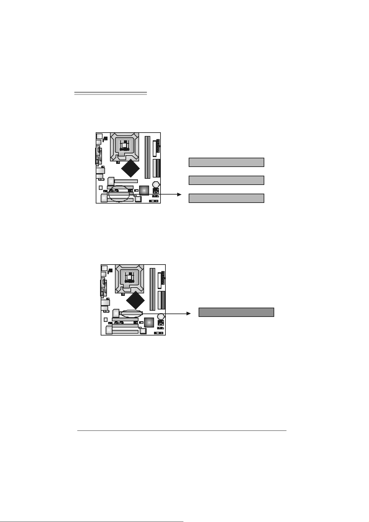
PCI1~PCI3: Periphe ral Component In terconnect Slots
This mot herboard is equipped with 3 st andard PCI slot s. PC I stands for
Peripheral Com ponent I nt erc onnect, and it is a bus st andard for ex pansion
cards . This PCI s lot is designat ed as 32 bits.
PCI1
PCI2
PCI3
AGP1: Accele rated Graphics Port Slot ( 865G Micro 775 only )
Your m onit or will attach direct ly to that v ideo card. This motherboard supports
video c ards f or PC I slots , but it is also equipped with an Accelerated Graphics
Port (AGP). An AGP card will tak e adv antage of AGP technology f or im prov ed
video efficiency and perf ormance, es pec ially with 3D graphics.
GP
11
Motherboard Manual
XGP1: Xtreme Graphics Port Slot ( 865GV Micro 775 only )
This XGP (Ex t rem e Graphics Port) s lot is a s pecial des ign that only s upports
com patible AGP VGA cards.
To inst all t he sy stem with an add-on AGP VGA card, please make sure t o install
the driver of add-on AGP VGA c ard bef ore onboard VGA driver inst allat ion. If t he
onboard VGA driv er has already been installed bef ore y ou install the add-on
AGP VGA c ard, the sys t em will aut om atically s et the onboard VGA as t he
primary graphics adapter.
For t he onboard VGA driver can’t be remov ed com plet ely, and to s olv e this
problem, please f ollow the steps below,
1. D is able onboard VGA utility under t he operating sys t em, and reboot PC. After
PC restarts, t he sys t em will autom atically s et the AGP VGA card as the
graphics adapter.
2. Or, re-inst all your operat ing sy s t em to ensure t he AGP VGA card function can
be used.
Note:
Pl e a se g o t o “ht tp://www.b i o st ar.co m.tw” fo r m o r e de ta i l e d inf o r mati o n about
XGP compatible AGP cards.
12
XGP
865G Micro 775 & 865GV Micro 775
_
)
CHAPTER 3: HE ADERS & J UMPERS SETUP
3.1 HOW TO SET UP JUMPERS
The illustration shows how to set up jumpers. When the jumper cap is
placed on pins, the jumper is “close”, if not, that means the j umper is
“open”.
Pin opened Pin closed Pin1-2 closed
3.2 DETAIL SETT INGS
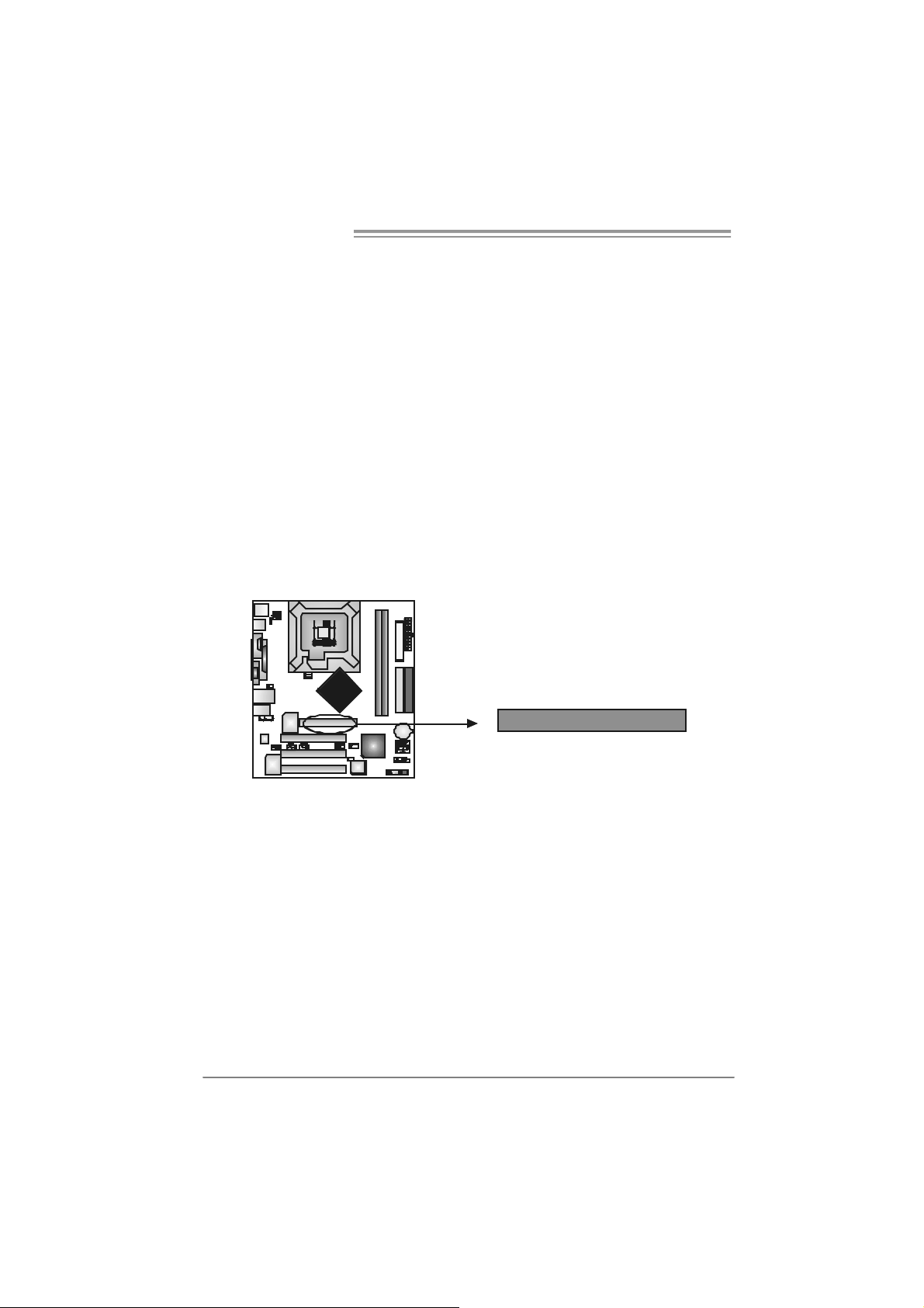
JPANEL1: Front Panel Header
This 22-pin connector includes Power-on, Reset, HDD LED , Power LED, Sleep
butt on, speaker and I rD A Connec t ion. I t allows user t o connect t he PC case’s
front panel switch fun ctions.
PWR
LED
SLP
++
12
111
+
SPK
HLED
On/Off
-
RST
IR (optional
22
Pin Assignment Function Pin Assignment Function
1 +5V 2 Sleep control
3 N/A 4 Ground
5 N/A 6 N/A N/A
7 Speaker
9 HDD LED (+) 1 0 Power LED (+)
11 HDD LED (-)
13 Ground 14 Power button
15 Reset control
17 N/A 18 Key
19 +5V 20 Ground
21 IRTX
Speaker
Connector
Hard drive
LED
Reset button
IrDA
Connector
8 Power LED (+)
12 Pow er LED (-)
16 Ground
22 IRRX
Sleep button
Powe r LED
Power-on button
IrDA Connector
13
Motherboard Manual
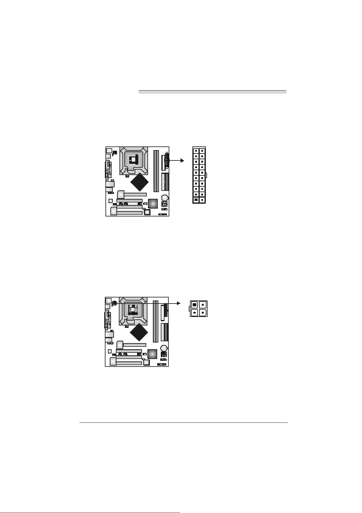
JATXPW R1: ATX Power S ou rce Conne ctor
This connector allows user t o connect 20-pin power connector on the ATX
power supply .
Pin Assignment
1 +3.3V
2 +3.3V
3 Ground
10
20
1
11
4 +5V
5 Ground
6 +5V
7 Ground
8 PW_OK
9 Standby Voltage
+5V
10 +12V
11 +3 .3V
12 -12V
13 Ground
14 PS_ON
15 Ground
16 Ground
17 Ground
18 -5V
19 +5V
20 +5V
JATXPW R2: ATX Power S ou rce Conne ctor
By c onnecting this c onnector, it will prov ide +12V t o C PU power circ uit.
14
13
24
Pin
1 +12V
2 +12V
3 Ground
4 Ground
Assignment
865G Micro 775 & 865GV Micro 775
JUSB2/JUSB3: Heade rs for USB 2.0 Ports at Fron t Panel
This header allows us er t o connect addit ional USB c able on t he PC f ront panel,
and also can be c onnec t ed wit h internal U SB dev ic es, like U SB card reader.
Assignment
Pin
1 +5V (fused)
2 +5V (fused)
3 USB4 USB5 USB+
6 USB+
7 Ground
2
1
10
9
JUSB2 JUSB3
JK B_USBV1/JU SBV 2/ JUSB3 _4 : P ower S o urce H ead er s for US B
Ports
Pin 1- 2 Close:
JKB_U SBV1: +5V for USB port s at JU SBLAN 1.
JU SBV2/JU SB3_4: +5V for USB ports at front panel (JU SB2/JUSB3).
Pin 2- 3 Close:
JKB_U SBV1: USB ports at JUSBLAN1 are powered by +5V s t andby
voltage.
JU SBV2/JU SB3_4: U SB ports at f ront panel (JU SB2/JU SB3) are powered
by +5V standb y voltage.
8 Ground
9 Key
10 NC
3
1
JKB_USBV1
13
31
Pin 1-2 close
JUSBV2
1
13
JUSBV3_4
3
Pin 2-3 close
Note:
In order to support this f unc tion “Power-On s y stem via U SB device,” “JKB_USBV1/
JUSBV2/JUSB3_4” jumper cap should be pl aced on Pin 2-3 individuall y.
3
1
3
1
15

Motherboard Manual
JAUDIO2: Front P anel Audio Header
This header allows us er to connect the front audio out put cable wit h the PC front
panel. It will dis able t he output on back panel audio connectors.
JCDIN1: CD-R OM Aud io-in Connector
This connector allows us er to c onnect the audio s ourc e from the variaty dev ices,
like CD-R OM, D VD -ROM, PC I sound card, PCI TV t urner card etc..
Pin Assignment
1 Mic in/center
2 Ground
3 Mic power/Bass
4 Audio power
5 Right li ne out/
Speaker out Right
6 Right li ne out/
Speaker out Right
7 Reserved
8 Key
9 Left line out/
2
1
14
13
Pin
14
Speaker out Left
10 Left line out/
Speaker out Left
11 Right line in/
Rear speaker
Right
12 Right line in/
Rear speaker
Right
13 Left line in/
Rear speaker Left
14 Left line in/
Rear speaker Left
Assignment
1 Left Channel
Input
2 Ground
3 Ground
4 Right Channel
Input
16
865G Micro 775 & 865GV Micro 775
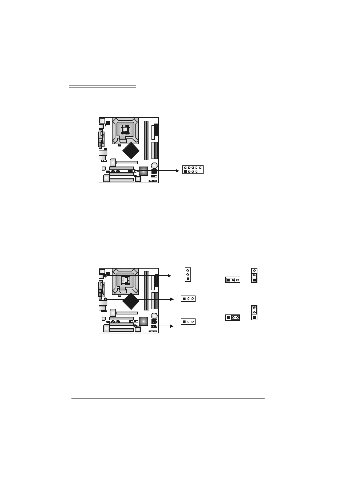
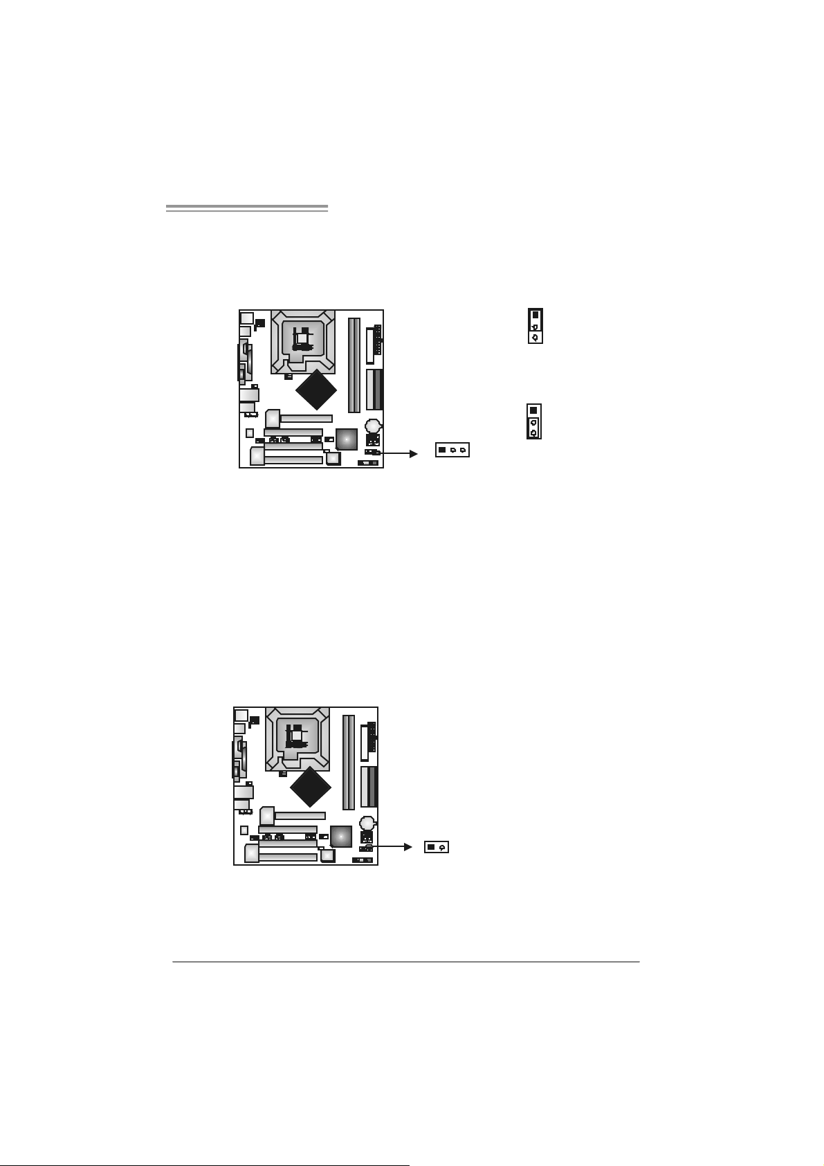
JCMOS 1: C lear CMO S H ea der
By plac ing the jum per on pin2-3, it allows user t o restore the BI OS safe set t ing
and the CMOS data, please c arefully f ollow t he proc edures to av oid damaging
the m otherboard.
1
3
Pin 1-2 Close:
Normal Operation (default).
1
13
3
Pin 2-3 Close:
Clear CMOS data.
※ Clear CMOS Procedures:
1. R em ov e AC power line.
2. Set the jumper to “Pin 2-3 close”.
3. Wait fo r five se co n ds.
4. Set the jumper to “Pin 1-2 close”.
5. Power on the AC.
6. R es et your desired pas s word or c lear the C MOS data.
JCI1: Chassis O pen Head er (optional)
This connector allows sy stem to monitor PC c as e open stat us. If the s ignal has
been triggered, it will rec ord t o the C MOS and s how the message on next
boot-up.
Pin
Assignment
1 Case open signal
2 Ground
12
17
Motherboard Manual
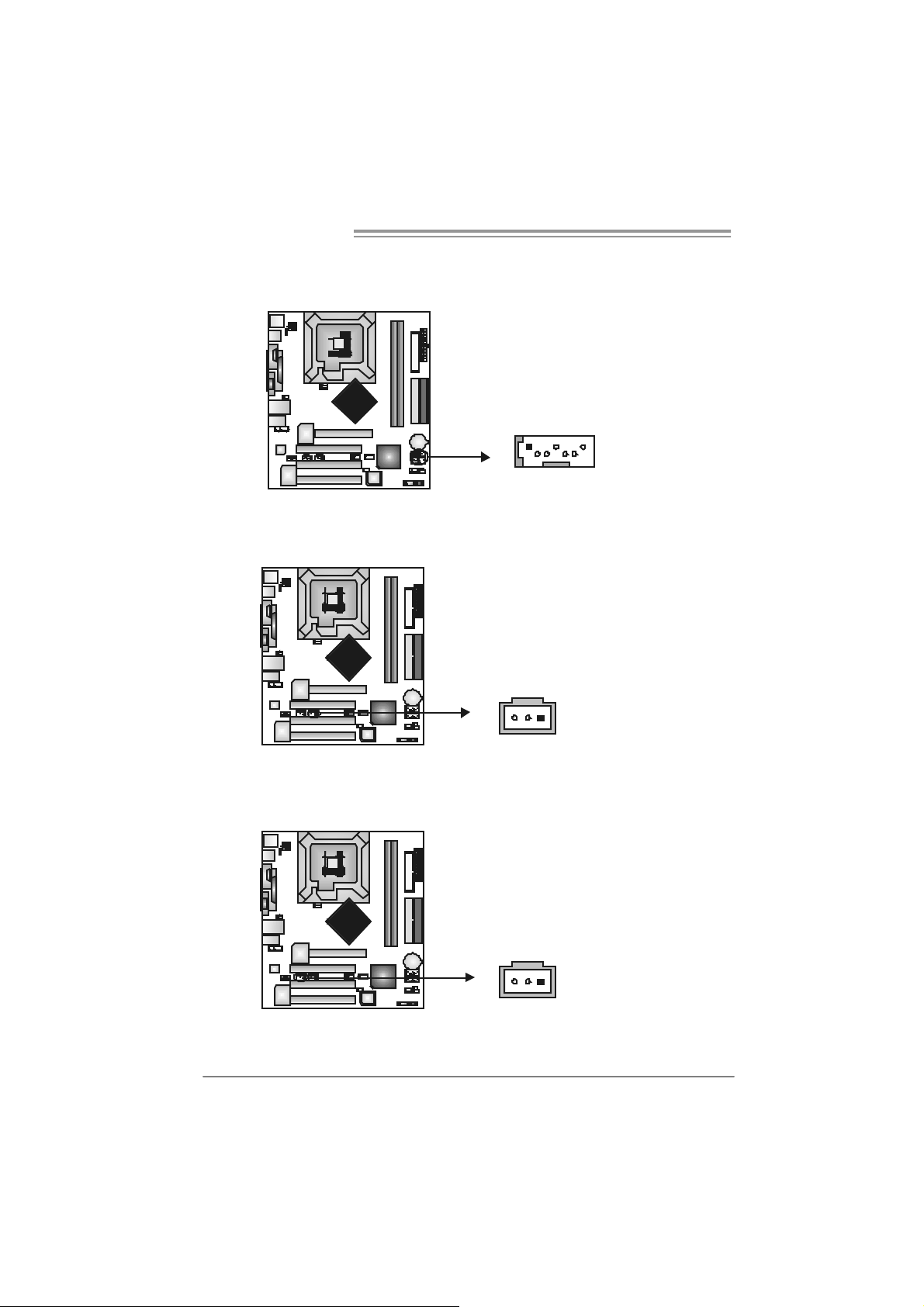
JSATA1~ JS ATA2 : Serial ATA Connectors
The motherboard has a PCI t o SATA C ont roller wit h 2 channels SATA interface,
it satisfies the SATA 1.0 spec and with transfer rate of 1.5GB/s.
JSPDIF_O UT1 : D igital Audio- out Conne ctor
This connector allows user t o connect the PCI bracket SPD IF out put header.
147
Pin
1 +5V
2 SPDIF_OUT
3 Ground
SATA2
SATA1
Assignment
Pin
Assignment
1 Ground
2 TX+
3 TX4 Ground
5 RX6 RX+
7 Ground
JSPDIF_IN1 (optional): Digital Audio-in Connector
This connector allows user t o connect the PCI bracket SPD IF input header.
18
13
Pin
1 +5V
2 SPDIF_IN
3 Ground
13
Assignment
865G Micro 775 & 865GV Micro 775
CHAPTER 5: USEFUL HELP
5.1 D
RIVER INSTALLATION NOTE
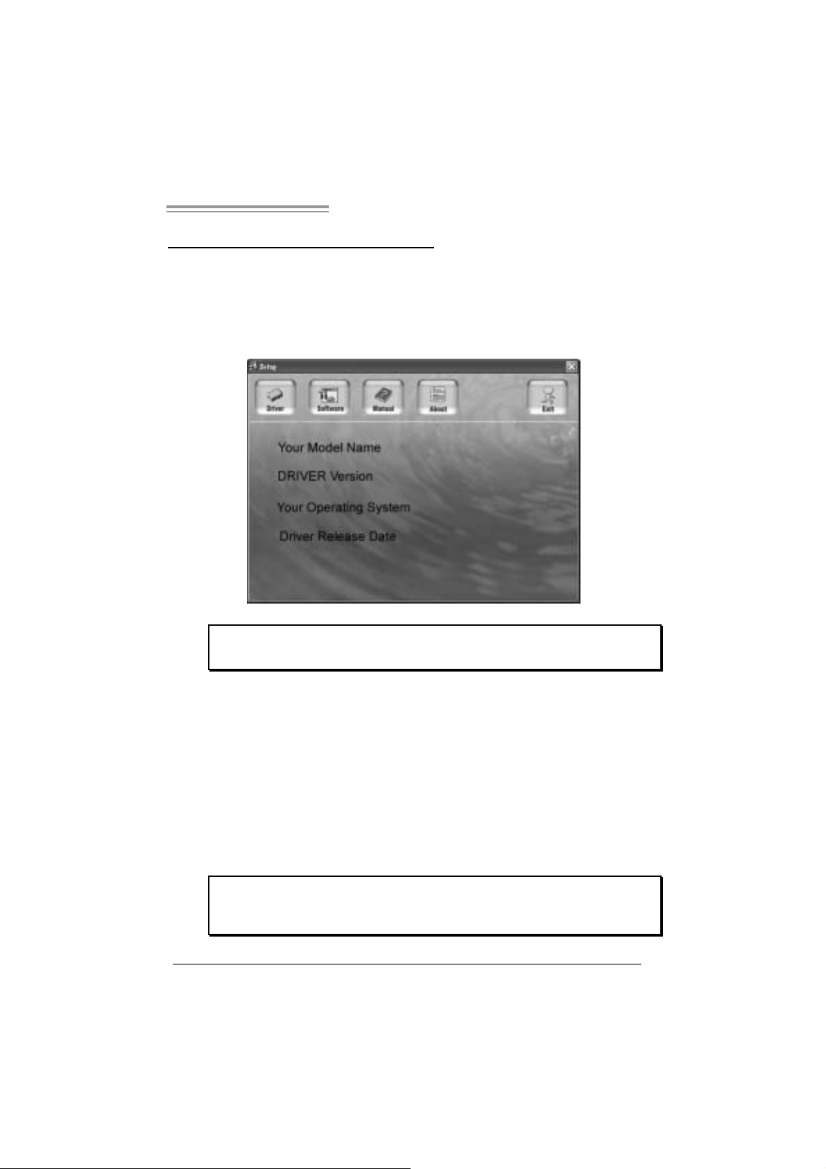
After you installed your operating system, please insert the Fully Setup
Driver CD into your optical drive and install the driver for better system
performance.
You wil l see the following wi ndow after you insert the CD
The setup guid e will aut o d et ect your motherboard and operating system.
Note:
If this window didn’t show up after you ins ert the Driver CD, please use file brow ser to
l ocate and e xecute t h e f il e SET U P.E XE under yo ur opti c al dr ive .
A. Driver Installation
To install the driver, pl ease cli ck on the Dri ver icon. The setup guide will
list the compatible driver for your motherboard and operating system.
Click on each device driver to launch the installation program .
B. Software Installation
To install the software, please cli ck on the Software i con. The setup guide
will list the software avail able for your system, click on each software title
to la unch th e ins tal lat io n pr ogr a m.
C. Manu al
Aside from the paperback manual, we also provi de manual in the Driver
CD. Cl i ck on the Manual icon to browse for availabl e manual.
Note:
You w ill need Acrobat Reader to open t he m an ual file . Please dow nload the latest version
of Acrobat Reader so ftware from
http://www.adobe.com/products/acrobat/readst ep2.html
19
Motherboard Manual
5.2 AWARD BIOS BEEP CODE
Beep Sound Meanin g
One long beep f ollowed by t wo s hort
beeps
High-low siren sound CPU overheated
One Short beep when system boot-up No error found during POST
Long beeps every ot her second No DRAM detected or inst all
Video card not f ound or v ideo card
mem ory bad
Sys t em will shut down automat ically
5.3 EXT RA INFORMATION
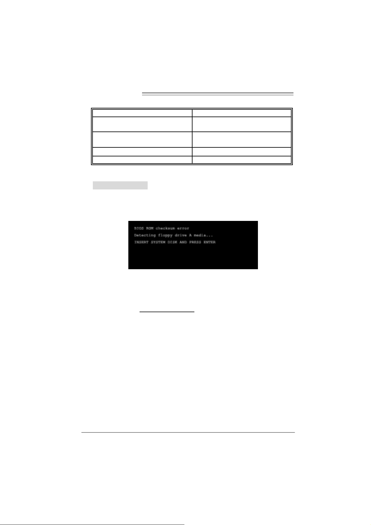
A. BIOS Update
After you fail to update BIOS or BIOS is in vaded by viru s, the
Boot-Block function will help to restore BIOS. If the following message
is shown after boot-up the system, it m eans the BIOS contents are
corrupted.
In this Case, please follow the procedure below to restore the BIOS:
1. Mak e a bootable fl op py dis k.
2. Download the Fl ash Utili ty “AWDFLASH.exe” from the Biostar
website: www.biostar.com.tw
3. Confirm motherboard model and download the respectively BIOS
fr om Bi os t ar w ebsit e.
4. Copy “AWDFLASH.exe” and respectivel y BIOS into fl oppy disk.
5. Insert the bootable disk into floppy drive and press Enter.
6. Sy stem will boot -up to DOS prompt .
7. Type “Awd flash xxxx.bf/ sn/py/ r” in DOS prompt.
(xxxx means BIOS name.)
8. Sy stem will update BIOS a utoma tically and restart.
9. The BIO S h as been recovered an d will work properly.
20

865G Micro 775 & 865GV Micro 775
B. CPU Overheated
If the system shutdown automatically after power on system for
seconds, that means the CPU protection function has been activated.
When the CPU is over heated, the motherboard will shutdown
automatically to avoid a damage of the CPU, and the system may not
power on again.
In this case, please double check:
1. The CPU cooler surface i s placed evenly with the CPU surface.
2. CPU fan is ro tated normally.
3. CPU fan speed is fulfil ling with the CPU speed.
After confirmed, please follow ste p s below to relief th e CPU
0protection function.
1. Remove the power cord from power suppl y for seconds.
2. Wait for sec onds.
3. Plug in the power cord and boot up the system.
Or you can:
1. Clear the CMOS data.
(See “Close CMOS Header: JCMOS1” section)
2. Wait for sec onds.
3. Power on the system again.
21
Motherboard Manual
e
5.4 TROUBLESHOOTING
Probable Solution
1. N o power to t he sy stem at all
Power light don’t illuminat e, fan
inside power s upply does not turn
on.
2. I ndic at or light on k ey board does
not t urn on.
Sys t em inoperat iv e. Key board lights
are on, power indic at or lights are lit,
and hard drive is s pinning.
Sys t em does not boot f rom hard dis k
drive, can be boot ed f rom opt ic al drive.
Sys t em only boot s f rom optical drive.
Hard disk can be read and applic ations
can be used but boot ing from hard disk
is imposs ible.
Screen m essage say s “Inv alid
Conf igurat ion” or “CMOS Failure. ”
Cannot boot sys t em after inst alling
sec ond hard drive.
1. Make s ure power cable is
sec urely plugged in.
2. Replace cable.
3. Contact techni cal support.
Us ing even pres s ure on both ends of
the DIMM, press down firm ly until the
module s naps int o plac e.
1. C hec k cable running from disk to
disk controller board. Make s ure
both ends are s ec urely plugged
i n; c h ec k the driv e t ype in the
standard CMOS se tup.
2. Bac k ing up t he hard drive is
ext rem ely im port ant . All hard
disk s are c apable of breaking
down at any t im e.
1. Bac k up dat a and applicat ions
files.
2. R ef ormat the hard drive.
Re-ins t all applicat ions and data
using backup disks.
Rev iew sys t em ’s equipment. Mak e sur
correc t information is in setup.
1. Set m as t er/slave jum pers
correctly.
2. R un SETUP program and selec t
correc t drive ty pes. Call t he driv e
manufac turers for co mpatibilit y
with other drives.
22

865G Micro 775 & 865GV Micro 775
CHAPTER 6: WARPSPEEDER™
6.1 INTRODUCTION
[WarpSpeeder™], a new powerful control utili ty, features three
user-friendly functions including Overclock Manager, Overvoltage
Manager, and Hardware Moni tor.
Wi th the Overcl ock Manager, users can easil y adjust the frequency they
prefer or they can get the best CPU performance with just one click. The
Overvoltage Manager, on the other hand, helps to power up CPU core
vol tage and Me mor y v ol ta ge. Th e co o l H ar dw are Moni tor s martly in d icates
the temperatures, voltage and CPU fan speed as well as the chi pset
information. Also, in the About panel, you can get detail descri ptions about
BIOS m odel and chipsets. In addi tion, the frequency status of CPU,
mem ory, AGP and PCI along with the CPU speed are synchronicall y
s how n on our ma i n p anel.
Moreover, to protect users' computer systems if the setting i s not
appropriate when testing and resul ts in system fail or hang,
[WarpSpeeder™] technology assures the system stability by automatically
rebooting the computer and then restart to a speed that is ei ther the
ori ginal system speed or a suitable one.
6.2 SYS TEM REQUIREMENT
OS Support: Windows 98 SE, Windows Me, Wi ndows 2000, Windows XP
DirectX: DirectX 8.1 or above. (The Windows XP operati ng system
includes DirectX 8.1. If you use Windows XP, you do not need to instal l
Dir ec tX 8.1.)
23
Motherboard Manual
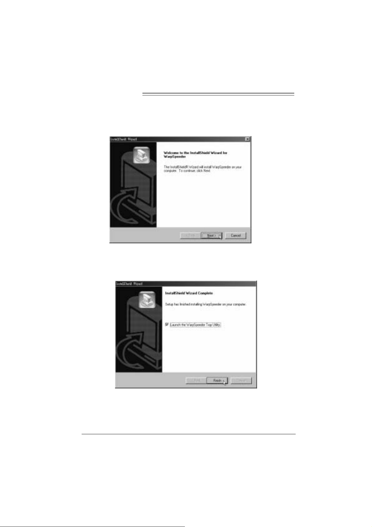
6.3 INSTALLATION
1. Execute the setup execution file, and then the following dial og will pop
up. Please click “Next” button and follow the default procedure to
install.
2. When you see the following dialog in setup procedure, it m eans setup
is completed. If the “Launch the WarpSpeeder Tray Uti lity” checkbox
is che c ked, the Tra y Icon utility and [WarpSp eeder™] utility will b e
automatically and imm ediatel y l aunched after you click “Finish”
button.
24
Usage :
The following figures are just only for reference, the screen printed in
this user man ual will chan ge acc ording to your mothe rbo ard on hand.
 Loading...