


P4M800-M7 & P4M800-M7 A
FCC Information and Copyright
This equipment has been tested and found to comply with the limits of a Class B digital device, pursuant to Part 15 of the FCC Rules. These limits are designed to provide reasonable protection against harmful interference in a residential installation. This equipment generates, uses and can radiate radio frequency energy and, if not installed and used in accordance with the instructions, may cause harmful interference to radio communications. There is no guarantee that interference will not occur in a particular installation.
The vendor makes no representations or warranties with respect to the contents here and specially disclaims any implied warranties of merchantability or fitness for any purpose. Further the vendor reserves the right to revise this publication and to make changes to the contents here without obligation to notify any party beforehand.
Duplication of this publication, in part or in whole, is not allowed without first obtaining the vendor’s approval in writing.
The content of this user’s manual is subject to be changed without notice and we will not be responsible for any mistakes found in this user’s manual. All the brand and product names are trademarks of their respective companies.
i

Table of Contents
Chapter 1: Introduction ............................................................... |
1 |
|
1.1 |
Features .............................................................................................. |
1 |
1.2 |
Package List ....................................................................................... |
3 |
1.3 |
Layout: P4M800-M7.......................................................................... |
4 |
1.4 |
Components: P4M800-M7 ............................................................... |
5 |
1.5 |
Layout: P4M800-M7 A (Rev 1.0) ..................................................... |
6 |
1.6 |
Components: P4M800-M7 A (Rev 1.0) ........................................... |
7 |
1.7 |
Layout: P4M800-M7 A (Rev 7.0) ..................................................... |
8 |
1.8 |
Components: P4M800-M7 A (Rev 7.0) ........................................... |
9 |
Chapter 2: |
Hardware Installation ........................................... |
10 |
2.1 |
Central Processing Unit (CPU)...................................................... |
10 |
2.2 |
FAN Headers................................................................................... |
11 |
2.3 |
Memory Module Installation ........................................................ |
12 |
2.4 |
Connectors and Slots ...................................................................... |
13 |
Chapter 3: Headers & Jumpers Setup................................... |
14 |
|
3.1 |
How to Setup Jumpers ................................................................... |
14 |
3.2 |
Detail Settings.................................................................................. |
14 |
Chapter 4: Useful Help .............................................................. |
18 |
|
4.1 |
Award BIOS Beep Code................................................................. |
18 |
4.2 |
Extra Information............................................................................ |
18 |
4.3 |
Troubleshooting .............................................................................. |
20 |
Chapter 5: WarpSpeeder™ ....................................................... |
21 |
|
5.1 |
Introduction..................................................................................... |
21 |
5.2 |
System Requirement....................................................................... |
21 |
5.3 |
Installation ....................................................................................... |
22 |
5.4 |
[WarpSpeeder™] includes 1 tray icon and 5 panels .................. |
23 |
ii
P4M800-M7 & P4M800-M7 A
CHAPTER 1: INTRODUCTION
1.1FEATURES
A. Hardware
CPU
Supports Socket 775.
Supports Intel Pentium 4 processor up to 3.8GHz.
Supports Dual Code CPU.
Front side bus at the following frequency ranges:
-533MT/s (133MHz Core Clock)
-800MT/s (200MHze Core Clock)
Supports Hyper-Threading Technology.
Chipset
North Bridge: VIA P4M800CD (for P4M800-M7).
VIA P4M800CE (for P4M800-M7 A v1.0 and v7.0).
South Bridge: VIA VT8237R.
Dimension
ATX Form Factor: 24.38cm (L) x 20.19cm (W)
Main Memory
Supports up to 2 DDR devices.
Supports 133/166/200MHz DDR devices.
Maximum memory size is up to 2GB. (Following table is only for reference.)
DIMM Socket |
DDR Module |
Total Memory |
|
Location |
Size |
||
|
|||
DIMM1 |
128MB/256MB/512MB/1GB *1 |
Max is 2GB. |
|
DIMM2 |
128MB/256MB/512MB/1GB *1 |
||
|
Super I/O
Chip: ITE IT8705AF
Provides the most commonly used legacy super I/O functionality.
Environment Control initiatives:
-H/W Monitor,
-Fan Speed Controller,
-ITE “Smart Guardian” function.
1
P4M800-M7 & P4M800-M7 A
Onboard IDE
Support 4 IDE disk drives.
Supports PIO mode 5, Bus Master, and Ultra DMA 33/66/100/133 function.
LAN
Chip: RealTek RTL8100C (for P4M800-M7/P4M800-M7 A v1.0) VIA VT6103L (for P4M800-M7 A v 7.0)
Supports 10/100 Mb/s auto-negotiation operation.
Half/Full duplex capability.
Supports ACPI, PCI power management.
Slot
3 PCI bus master slots.
1 AGP 4x/8x compatible slot.
1 CNR slot.
Serial ATA
Integrated in VT8237R.
Supports RAID 0 and RAID 1 functions. Supports 2 serial ATA (SATA) ports.
-Complaints with SATA Version 1.0 specification.
-Data transfer rates up to 150 MB/s.
Onboard AC’97 Sound Codec
Chip: ALC655
Supports 6 channels.
Supports S/PDIF out function.
Compliant with AC’97 Version 2.3 specification.
Front Side Onboard Peripherals
1 front panel header supports front panel facilities.
1 S/PDIF out connector supports digital audio out function (optional).
1 CD-in connector supports 1 CD-ROM audio-in device.
1 front audio header supports front panel audio function.
1 chassis open header supports PC case-opened warning function.
1 Floppy port supports 2 FDD with 360K, 720K, 1.2M, 1.44M and 2.88Mbytes.
2 USB headers support 4 USB 2.0 ports.
2
P4M800-M7 & P4M800-M7 A
2 IDE connectors support 4 hard disk devices.
2 serial ATA connectors support 2 SATA devices.
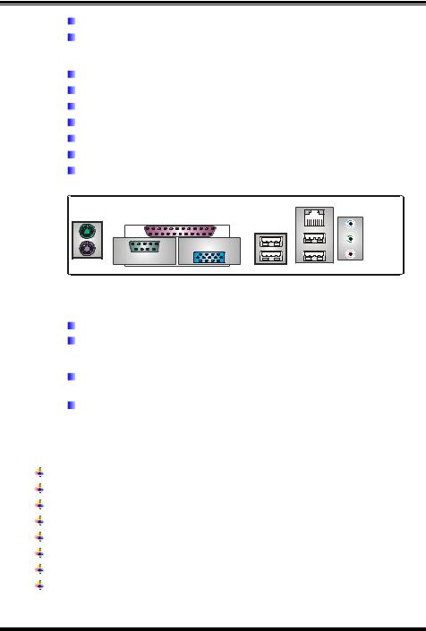
Rear Side Connectors
4 USB 2.0 ports.
1 VGA port.
1 serial port.
1 parallel port.
1 RJ-45 LAN jack.
1 PS/2 Mouse & Keyboard port.
1 vertical audio port including 1 line-in connector, 1 line out connector, and 1 MIC in connector.
PS/2 |
|
Mouse |
Printer Port |
|
VGA1
COM1
PS/2
Keyboard
LAN |
USB x2 |
USB x2 |
Line In/
Surround
Line Out
Mic In 1/
Base/Center
B. BIOS & Software
BIOS
Award legal BIOS.
Supports APM1.2, ACPI, and USB functions.
Software
Supports 9th TouchTM, FlasherTM, WinFlasherTM, and WarpspeederTM.
Offers the highest performance for Windows 98SE, Windows NT, Windows 2000, Windows ME, Windows XP, Red-Hat Linux, and UNIX series.
1.2PACKAGE LIST
FDD cable x1
HDD cable x1
User’s Manual x1
Fully Setup Driver CD x1
Rear I/O panel for ATX case x1
USB 2.0 cable x1 (optional)
Serial ATA cable x2 (optional)
S/PDIF out cable x1 (optional)
3
P4M800-M7 & P4M800-M7 A
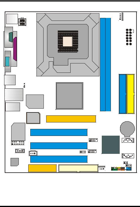
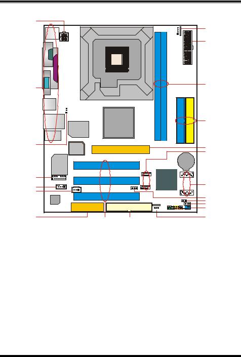
1.3 LAYOUT: P4M800-M7 |
||
JKBMS1 |
|
|
JCOM1 |
LGA775 |
|
JATXPWR2 |
|
|
COM 1 |
CPU1 |
|
Port Parallel |
||
|
||
VGA1 |
|
|
JVGA1 |
|
|
JUSB1 |
|
|
JUSBV1 |
|
|
1 |
|
|
JUSBLAN1 |
P4M800CD |
|
Super |
||
|
||
I/O |
|
|
JAUDIO |
|
|
1
JCFAN1
DIMM1 |
DIMM2 |
IDE1
 JATXPWR1
IDE2
BIOS |
AGP1 |
|
LAN |
|
|
PCI1 |
|
|
BAT1 |
|
RTL8100C |
|
|
|
|
|
||
|
|
|
|
2 |
JUSB3 10 |
|
1 |
2 |
14 |
|
|
1 |
7 |
|
|
1 |
13 |
|
PCI2 |
|
VT8237R |
|
JSATA2 |
JAUDIO1 |
|
|
|
|
|
||
|
|
|
|
|
JUSB4 |
|
|
|
1 |
JSPDIFO1 |
1 |
2 |
10 |
|
JSATA1 |
JCDIN1 |
|
1 |
|
|
|||
1 |
(optional) |
|
JUSBV2 |
1 |
|
7 |
|
|
|
|
|
|
|
||
Codec |
|
|
PCI3 |
|
|
|
JCI1 |
|
|
|
|
|
1 |
||
|
|
|
|
|
JCMOS1 |
||
CNR1 |
FDD1 |
1 |
JPANEL1 |
1 |
2 |
24 |
|||
|
|
JSFAN1 |
1 |
23 |
|
|
|
|
Note: ■ represents the 1st pin.
4
P4M800-M7 & P4M800-M7 A
1.4COMPONENTS: P4M800-M7
A |
|
|
|
|
U |
|
LGA775 |
T |
|
|
|
|
CPU1 |
|
B |
|
S |
|
|
|
|
P4M800CD |
R |
Super |
|
|
|
|
|
I/O |
|
|
C |
|
Q |
BIOS |
|
|
|
|
P |
BAT1
LAN
D |
|
|
VT8237R |
|
|
|
|
E |
|
|
O |
|
|
|
|
F |
|
|
|
|
Codec |
|
N |
|
|
M |
|
|
|
|
L |
|
|
|
K |
G |
H |
I |
J |
|
|
||
A. JATXPWR2: ATX power connector. |
L. JCMOS1: Clear CMOS header. |
||
B.Back panel connectors (rear side). M. JCI1: Chassis open message header.
C.JUSBV1: USB power header for JKBMS1, JUSB1, and JUSBLAN1.
D.JAUDIO1: Front panel audio out header.
N.JUSBV2: USB power header for JUSB3/4.
O.JSATA1/2: Serial ATA connectors.
E.JCDIN1: CD-ROM audio in connector. P. JUSB3/4: Front USB headers.
F.JSPDIFO1 (optional): Digital audio out Q. AGP1: Accelerated Graphics Port slot. connector.
G. CNR1: Communication Network Riser |
R. IDE1/2: Hard disk connectors. |
slot. |
|
H. PCI1~3: Peripheral Component |
S. DIMM1/2: DDR memory modules. |
Interconnect slots. |
|
I.FDD1: Floppy disk connector. T. JATXPWR1: ATX power connector.
J. JSFAN1: System fan header. |
U. JCFAN1: CPU fan header. |
K.JPANEL1: front panel facilities header.
5

P4M800-M7 & P4M800-M7 A
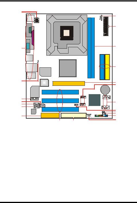
1.5LAYOUT: P4M800-M7 A (REV 1.0)
JKBMS1 |
JATXPWR2 |
JCOM1 |
JPRNT1 |
JVGA1 |
JUSB1 |
JUSBV1 |
|
|
JUSBLAN1 |
|
|
Super |
|
I/O |
JAUDIO |
|
JATXPWR1
JCFAN1
LGA775
CPU1
DIMM1 |
DIMM2 |
P4M800CE |
IDE1 |
IDE2 |
|
|
|
BIOS |
AGP1 |
|
|
|
|
|
||
LAN |
|
|
|
BAT1 |
|
|
|
||
|
PCI1 |
|||
RTL8100C |
|
|
|
|
|
|
|
|
|
JUSB3
JAUDIO1 |
PCI2 |
VT8237R |
JSATA2 |
|
|
||||
JCDIN1 |
|
JUSB4 |
|
|
JSPDIFO1 |
|
|
JSATA1 |
|
JAUX1 |
JUSBV2 |
|
||
(optional) |
|
|
||
(optional) |
PCI3 |
|
|
|
Codec |
|
|
|
|
|
JSFAN1 |
|
JCI1 |
|
|
CNR1 |
JPANEL1 |
JCMOS1 |
|
|
FDD1 |
|
||
|
|
|
||
Note: ■ represents the 1st pin.
6
P4M800-M7 & P4M800-M7 A
1.6COMPONENTS: P4M800-M7 A (REV 1.0)
A |
|
|
V |
LGA775 |
U |
|
|
B |
T |
|
|
P4M800CE |
S |
|
C |
R |
|
|
|
Q |
D |
|
VT8237R |
E |
|
|
|
P |
|
F |
|
|
G |
|
|
|
|
O |
|
|
N |
H |
|
M |
|
L |
|
I |
J |
K |
|
A.JATXPWR2: ATX power connector.
B.Back panel connectors (rear side).
L.JPANEL1: front panel facilities header.
M.JCMOS1: Clear CMOS header.
C.JUSBV1: USB power header for back N. JCI1: Chassis open message header. panel.
D.JAUDIO1: Front panel audio out O. JUSBV2: USB power header for front
header. |
panel. |
E.JSPDIFO1 (optional): Digital audio out P. JSATA1/2: Serial ATA connectors. connector.
F.JCDIN1: CD-ROM audio in connector. Q. JUSB3/4: Front USB headers.
G. |
CNR1: Communication Network Riser |
R. |
AGP1: Accelerated Graphics Port slot. |
H. |
slot. |
S. IDE1/2: Hard disk connectors. |
|
JAUX1: |
|||
I. |
PCI1~3: Peripheral Component |
T. |
DIMM1/2: DDR memory modules. |
|
Interconnect slots. |
|
|
J.FDD1: Floppy disk connector. U. JATXPWR1: ATX power connector.
K. JSFAN1: System fan header. |
V. JCFAN1: CPU fan header. |
7
P4M800-M7 & P4M800-M7 A
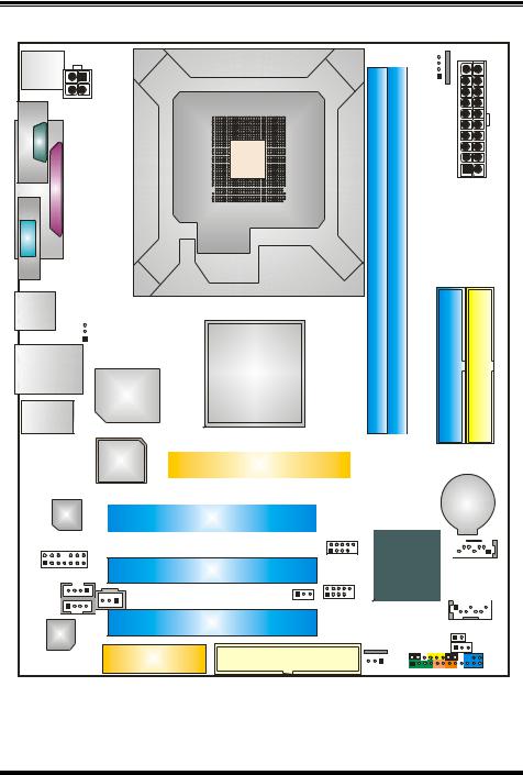
1.7LAYOUT: P4M800-M7 A (REV 7.0)
JKBMS1 |
JATXPWR2 |
JCOM1 |
JPRNT1 |
JVGA1 |
JUSB1 |
JUSBV1 |
|
|
JUSBLAN1 |
|
|
Super |
|
I/O |
JAUDIO |
|
JATXPWR1
JCFAN1
LGA775
CPU1
DIMM1 |
DIMM2 |
P4M800CE |
IDE1 |
IDE2 |
|
|
|
BIOS |
AGP1 |
|
|
|
|
|
||
LAN |
|
|
|
BAT1 |
|
|
|
||
|
PCI1 |
|||
VT6103L |
|
|
|
|
|
|
|
|
|
JUSB3
JAUDIO1 |
PCI2 |
VT8237R |
JSATA2 |
|
|
||||
JCDIN1 |
|
JUSB4 |
|
|
JSPDIFO1 |
|
|
JSATA1 |
|
JAUX1 |
JUSBV2 |
|
||
(optional) |
|
|
||
(optional) |
PCI3 |
|
|
|
Codec |
|
|
|
|
|
JSFAN1 |
|
JCI1 |
|
|
CNR1 |
JPANEL1 |
JCMOS1 |
|
|
FDD1 |
|
||
|
|
|
||
Note: ■ represents the 1st pin.
8
 Loading...