


A780LB

A740G M2L+/A780LB Setup Manual
FCC Information and Copyright
This equipment has been tested and found to comply with the limits of a Class
B digital device, pursuant to Part 15 of the FCC Rules. These limits are designed
to provide reasonable protection against harmful interference in a residential
installation. This equipment generates, uses, and can radiate radio frequency
energy and, if not installed and used in accordance with the instructions, may
cause harmful interference to radio communications. There is no guarantee
that interference will not occur in a particular installation.
The vendor makes no representations or warranties with respect to the
contents here and specially disclaims any implied warranties of merchantability
or fitness for any purpose. Further the vendor reserves the right to revise this
publication and to make changes to the contents here without obligation to
notify any party beforehand.
Duplication of this publication, in part or in whole, is not allowed without first
obtaining the vendor’s approval in writing.
The content of this user’s manual is subject to be changed without notice and
we will not be responsible for any mistakes found in this user’s manual. All the
brand and product names are trademarks of their respective companies.

Table of Contents
Chapter 1: Introduction ............................................................ 1
1.1 Before You Start ................................................................................ 1
1.2 Package Checklist............................................................................. 1
1.3 Motherboard Features...................................................................... 2
1.4 Rear Panel Connectors ..................................................................... 3
1.5 Motherboard Layout......................................................................... 4
Chapter 2: Hardware Installation ............................................. 5
2.1 Installing Central Processing Unit (CPU)....................................... 5
2.2 FAN Headers...................................................................................... 7
2.3 Installing System Memory ................................................................ 8
2.4 Connectors and Slots....................................................................... 10
Chapter 3: Headers & Jumpers Setup .................................. 13
3.1 How to Setup Jumpers .................................................................... 13
3.2 Detail Settings.................................................................................. 13
Chapter 4: RAID Functions ..................................................... 18
4.1 Operating System............................................................................ 18
4.2 Raid Arrays...................................................................................... 18
4.3 How RAID Works............................................................................. 18
Chapter 5: Useful Help ............................................................ 21
5.1 Driver Installation Note.................................................................. 21
5.2 Software............................................................................................ 22
5.3 Extra Information............................................................................ 26
5.4 Troubleshooting............................................................................... 28
Appendix: SPEC In Other Languages ...................................... 29
German.................................................................................................................. 30
French .................................................................................................................... 32
Italian..................................................................................................................... 34
Spanish ................................................................................................................... 36
Portuguese ............................................................................................................ 38
Polish...................................................................................................................... 40
Russian ................................................................................................................... 42
Arabic..................................................................................................................... 44
Japanese ................................................................................................................ 46
A740G M2L+/A780LB
1
CHAPTER 1: INTRODUCTION
1.1 B
EFORE YOU START
Thank you for choosing our product. Before you start installing the
motherboard, please make sure you follow the instructions below:
Prepare a dry and stable working environment with
sufficient lighting.
Always disconnect the computer from power outlet
before operation.
Before you take the motherboard out from anti-static
bag, ground yourself properly by touching any safely
grounded appliance, or use grounded wrist strap to
remove the static charge.
Avoid touching the components on motherboard or the
rear side of the board unless necessary. Hold the board
on the edge, do not try to bend or flex the board.
Do not leave any unfastened small parts inside the
case after installation. Loose parts will cause short
circuits which may damage the equipment.
Keep the computer from dangerous area, such as heat
source, humid air and water.
1.2 PACKAGE CHECKLIST
HDD Cable X 1 (optional)
Serial ATA Cable X 2
Rear I/O Panel for ATX Case X 1
Installation Guide X 1
Fully Setup Driver CD X 1 (full version manual files inside)
FDD Cable X 1 (optional)
USB 2.0 Cable X1 (optional)
S/PDIF out Cable X 1 (optional)
Serial ATA Power Cable X 1 (optional)
Note: The package contents may be different due to area or your motherboard version.
Motherboard Manual
2
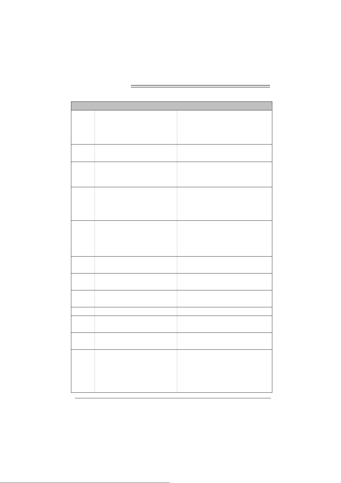
1.3 MOTHERBOARD FEATURES
SPEC
CPU
Socket AM2+
AMD Sempron / Athlon / Athlon II / Phenom
/ Phenom II processors
(Maximum Watt: 95W)
AMD 64 Architecture enables 32 and 64 b it
computing
Supports Hyper Transport 2.0
FSB
Support HyperTransport 2.0
Supports up to 2 GT/s Bandwidth
Chipset
AMD 740G (A740G M2L+)
AMD 780L (A780LB)
AMD SB710
Super I/O
ITE 8718F
Prov ides the mos t co mmonly used legac y
Super I/O functionality
Low Pin Count Interface
En viro nment Cont rol in it iatives
H/W Mon itor
ITE's "S mart Guard ian" funct ion
Main
Memory
DDR2 DIMM Slots x 2
Max Memory Capacity 8GB
Each DIMM supports 256MB/512MB/
1GB/2GB/4GB DDR2
Dual Channe l Mod e DDR2 memory modu le
Supports DDR2 533 / 667 / 800
Supports DDR2 1066 (by AM2+/AM3 CPU)
Register ed DIMM and ECC D IMM is not supported
Graphics Integr ated in AMD 74 0G Chipset
Max S hared V ideo Me mo ry is 5 12MB
Avivo support
IDE Int eg r ated ID E Cont ro ller
Ultra DMA 33 / 66 / 100 / 133 Bus Master Mode
supports PIO Mode 0~4,
SATA II Integrated Serial ATA Controller
Data transfer rates up to 3 Gb/s
SATA Versio n 2.0 s pecif icat ion co mpl ian t
LAN Realtek RTL 8102EL 10 / 100 Mb/s auto negot iation
Sound ALC662
5.1 channels audio out
High Definition Audio
PCI Express X16 slot x1 Supports PCI-E X16 expansion cards
Slots
PCI slot x2 Supports PCI expansion cards
Floppy Connector x1 Each connector supports 2 Floppy drives
IDE Connector x1 Each connector supports 2 IDE device
SATA Connector x4 Each connector supports 1 SATA devices
Front Panel Connector x1 Supports front panel facilities
On Board
Connectors
Front Audio Connector x1 Supports front panel audio function
A740G M2L+/A780LB
3
SPEC
S/PDIF out Connector x1 Supports digital audio out function
CPU Fan Header x1 CPU Fan power supply (with Smart Fan function)
System Fan Header x1 System Fan Power supply
CMOS clear Header x1 Restore CMOS data to factory default
USB Connector x2 Each connect or supports 2 front panel USB po rts
Power Connector (24pin) x1 Connects to Power supply
Power Connector (4pin) x1 Connects to Power supply
Printer Port Connector x1 Each connector supports 1 Printer port
Back Panel
I/O
PS/2 Keyboard x1
PS/2 Mous e x1
VGA port x1
LAN port x1
USB Port x4
Audio Jack x3
Connects to PS/2 Keyboard
Connects to PS/2 Mouse
Connect to D-SUB monitor
Connect to RJ-45 Ethernet cable
Connect t o USB devices
Provide Audio-In/Out and microphone connection
Board Size 182 mm(W) x 235 mm(L)
Special
Features
RAID 0 / 1 / 1+0 support
OS Support Windows XP / Vista 32 / Vista 64 / 7
Biostar reserves the right to add or remove support
for any OS With or without notice.
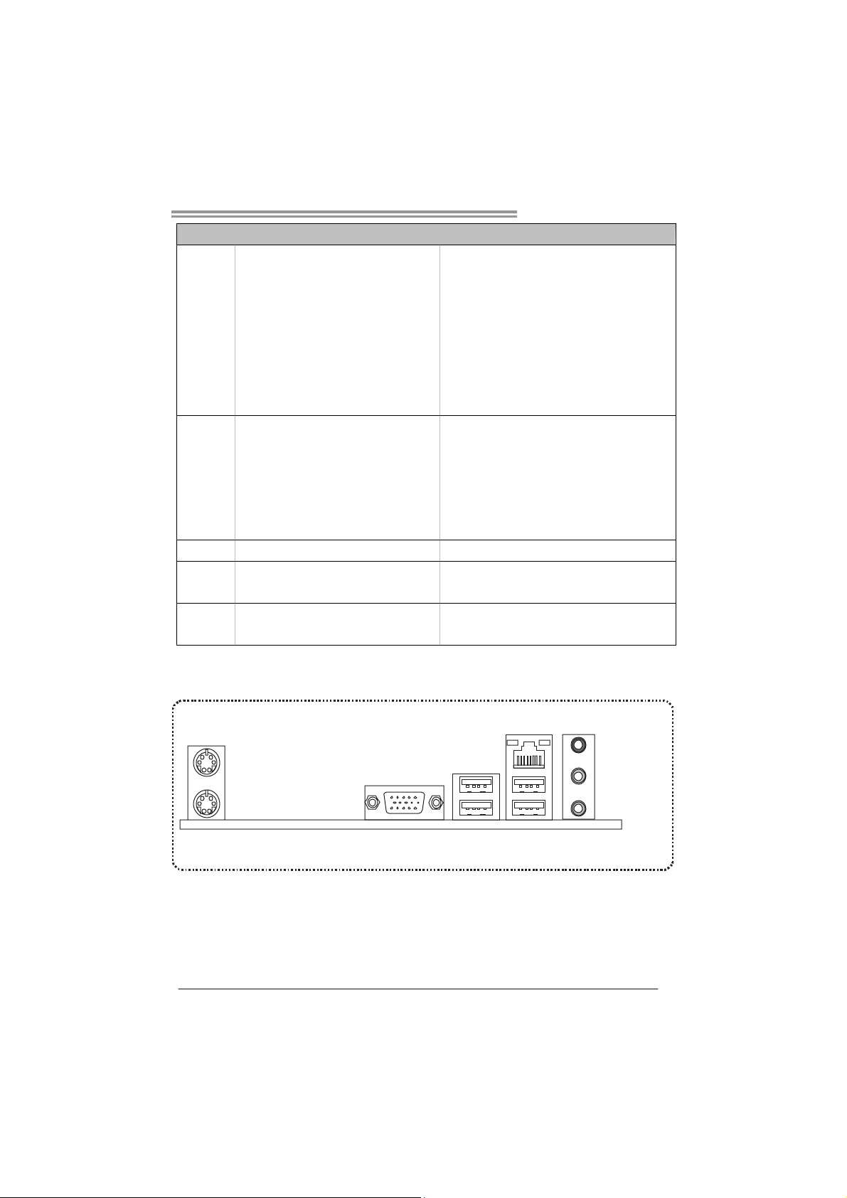
1.4 R
EAR PANEL CONNECTORS
PS/2
Mouse
PS/2
Keyboard
USBX2USBX2
LAN
VGA
Line In/
Surround
Line Out
Mic In 1/
Bass/ Cent er
Motherboard Manual
4
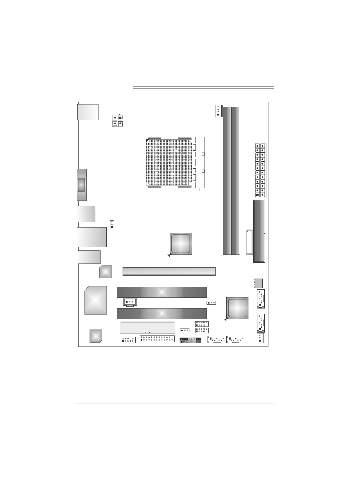
1.5 MOTHERBOARD LAYOUT
KBMS 1
USB1
RJ45USB1
VGA1
AUD IO1
JUSBV1
AT XP W R2
LAN
Super
I/O
Codec
F_AU DIO1
J_PRINT1
PEX16_1
PCI1
PCI2
JCMO S1
JSPD IFOUT1
FD D1
JUSB V2
F_USB2
F_USB1
PANEL 1 SATA1 SATA2
SYS_FAN1
SATA3
SATA4
BI OS
IDE1
BATTERY
AMD
SB710
AMD
740G/
A780L
DIMMA1
DIMMB1
CPU_FAN1
Socket AM2+
ATXPW R1
Note: represents the 1■
st
pin.
A740G M2L+/A780LB
5
CHAPTER 2: HARDWARE INSTALLATION
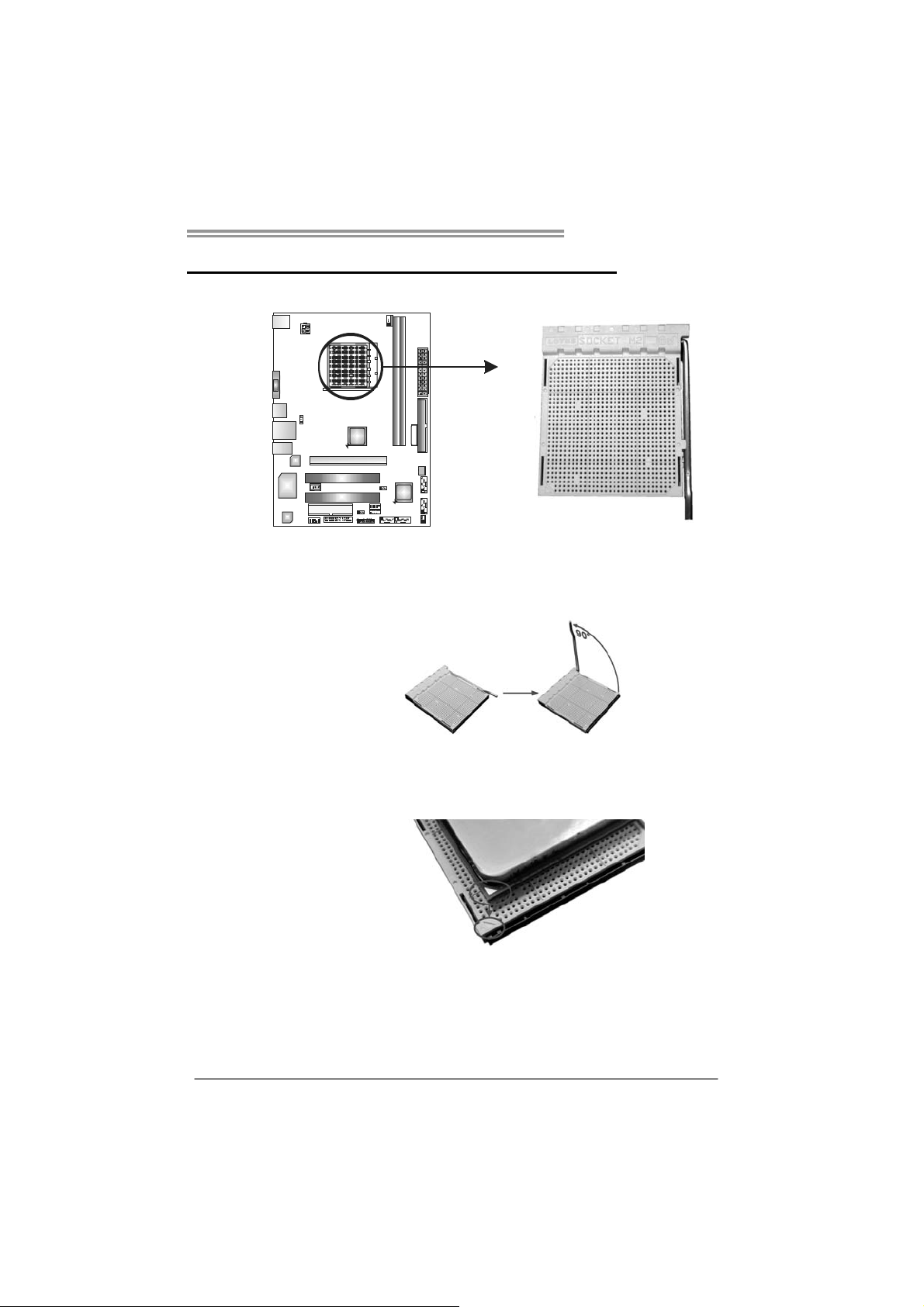
2.1 I
NSTALLING CENTRAL PROCESSING UNIT (CPU)
Step 1: Pull the lever toward direction A from the socket and then raise the
lever up to a 90-degree angle.
Step 2: Look for the white triangle on socket, and the gold triangle on
CPU should point towards this white triangle. The CPU will fit only
in the correct orientation.
Motherboard Manual
6
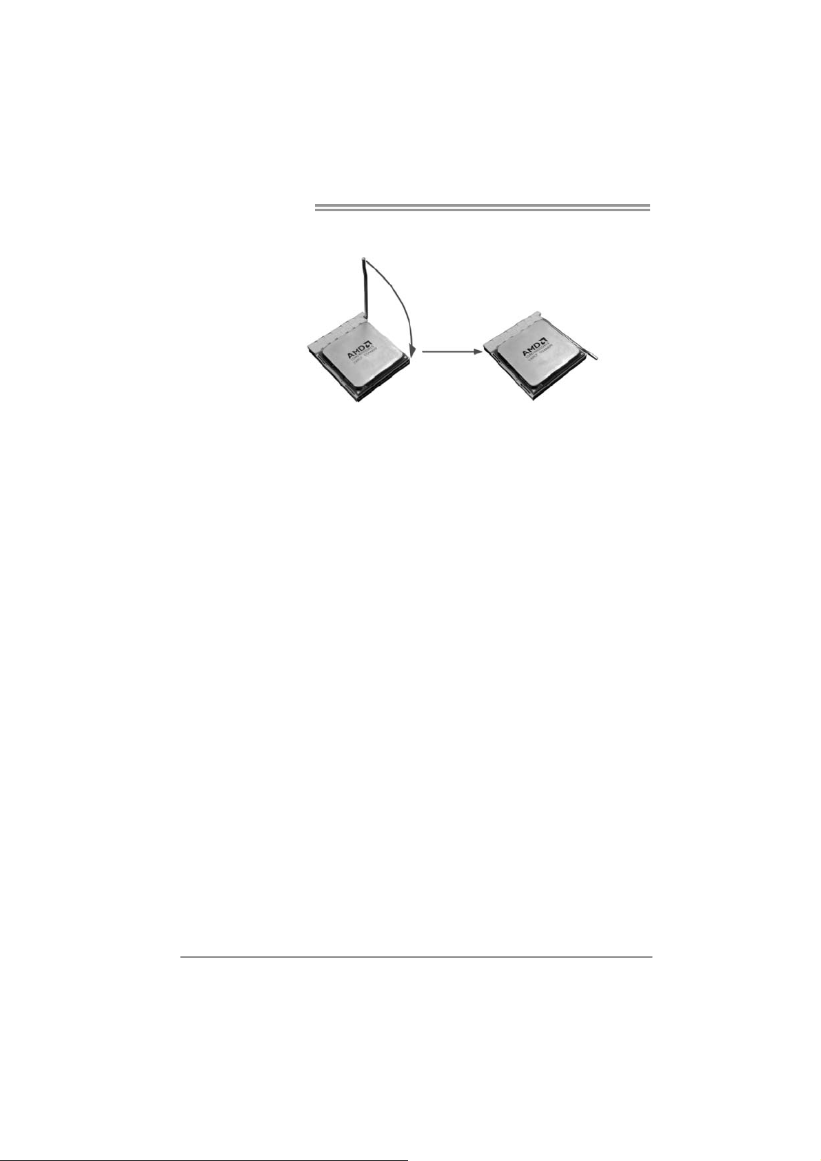
Step 3: Hold the CPU down firmly, and then close the lever toward direct
B to complete the installation.
Step 4: Put the CPU Fan on the CPU and buckle it. Connect the CPU
FAN power cable to the CPU_FAN1. This completes the
installation.
Note: Please update the BIOS to the latest version while using AM2+/AM3 CPUs. Due to the latest
CPU transition, you may encounter the situation that the new system failed to boot while
using new AM2+/AM3 CPUs. In this case, please install one standard AM2 CPU to boot your
system, and update the latest BIOS from our website for AM2+/AM3 CPUs support.
A740G M2L+/A780LB
7
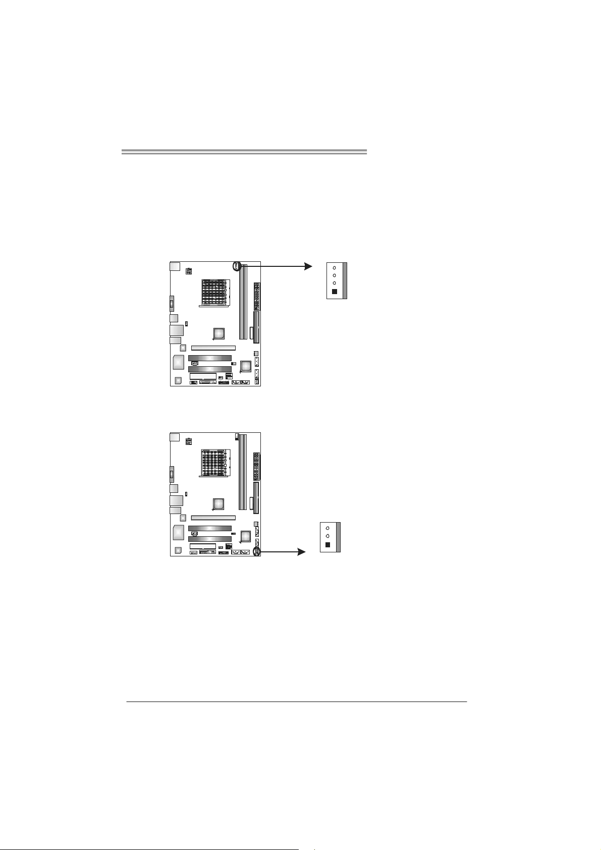
2.2 FAN HEADERS
These fan headers support cooling-fans built in the computer. The fan
cable and connector may be different due to the fan manufacturer.
Connect the fan cable to the connector while matching the black wire to
pin#1.
CPU_FAN1: CPU Fan Header
Pin
Assignment
1 Ground
2 +12V
3
FAN RPM r at e
sense
1
4
4 Smart Fan
Control (By Fan)
SYS_FAN1: System Fan Header
Pin
Assignment
1 Ground
2 +12V
1
3
3 FAN RPM rate
sense
Note:
The CPU_FAN1 supports 4-pin head connector. The SYS_FAN1 supports 3-pin head
connector. When connecting with wires onto connectors, please note that the red wire is
the positive and should be connected to pin#2, and the black wire is Ground and should
be connected to GND.
Motherboard Manual
8
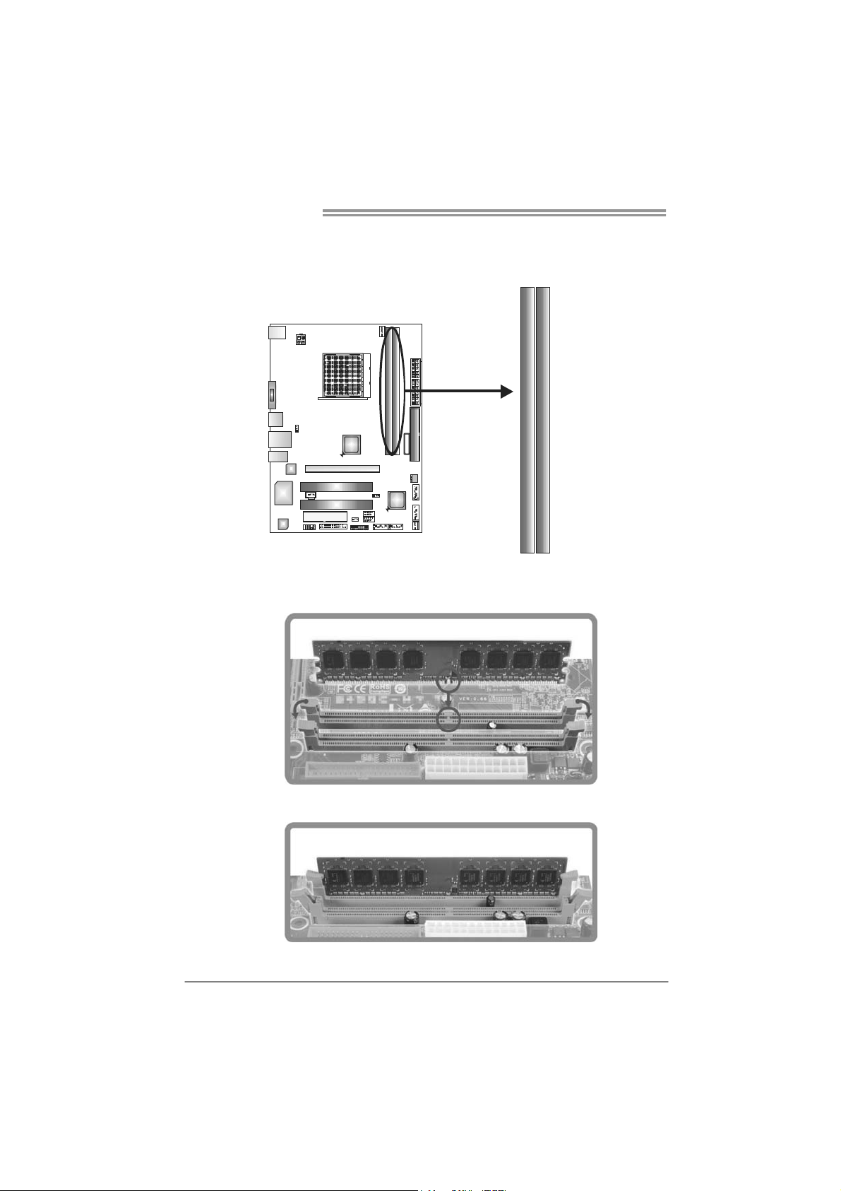
2.3 INSTALLING SYSTEM MEMORY
A. Memory Modules
DIMM B1
DIMM A1
1. Unlock a DIMM slot by pressing the retaining clips outward. Align a
DIMM on the slot such that the notch on the DIMM matches the
break on the Slot.
2. Insert the DIMM vertically and firmly into the slot until the retaining
chip snap back in place and the DIMM is properly seated.
A740G M2L+/A780LB
9
B. Memory Capacity
DIMM Socket
Location
DDR2 Module
Total M emory
Size
DIMMA1 256MB/512MB/1GB/2GB/4GB
DIMMB1 256MB/512MB/1GB/2GB/4GB
Max is 8GB.
C. Dual Channel Memory installation
Please refer to the following requirements to activate Dual Channel function:
Install memory module of the same density in pairs, shown in the table.
Dual Channel Status
DIMMA1
DIMMB1
Disabled O X
Disabled X O
Enabled O O
(O means memory installed, X means memory not installed.)
The DRAM bus width of the memory module must be the same (x8 or
x16)
Motherboard Manual
10
2.4 CONNECTORS AND SLOTS
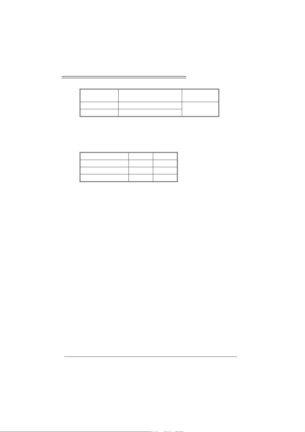
FDD1: Floppy Disk Connector
The motherboard provides a standard floppy disk connector that supports 360K,
720K, 1.2M, 1.44M and 2.88M floppy disk types.
133
234
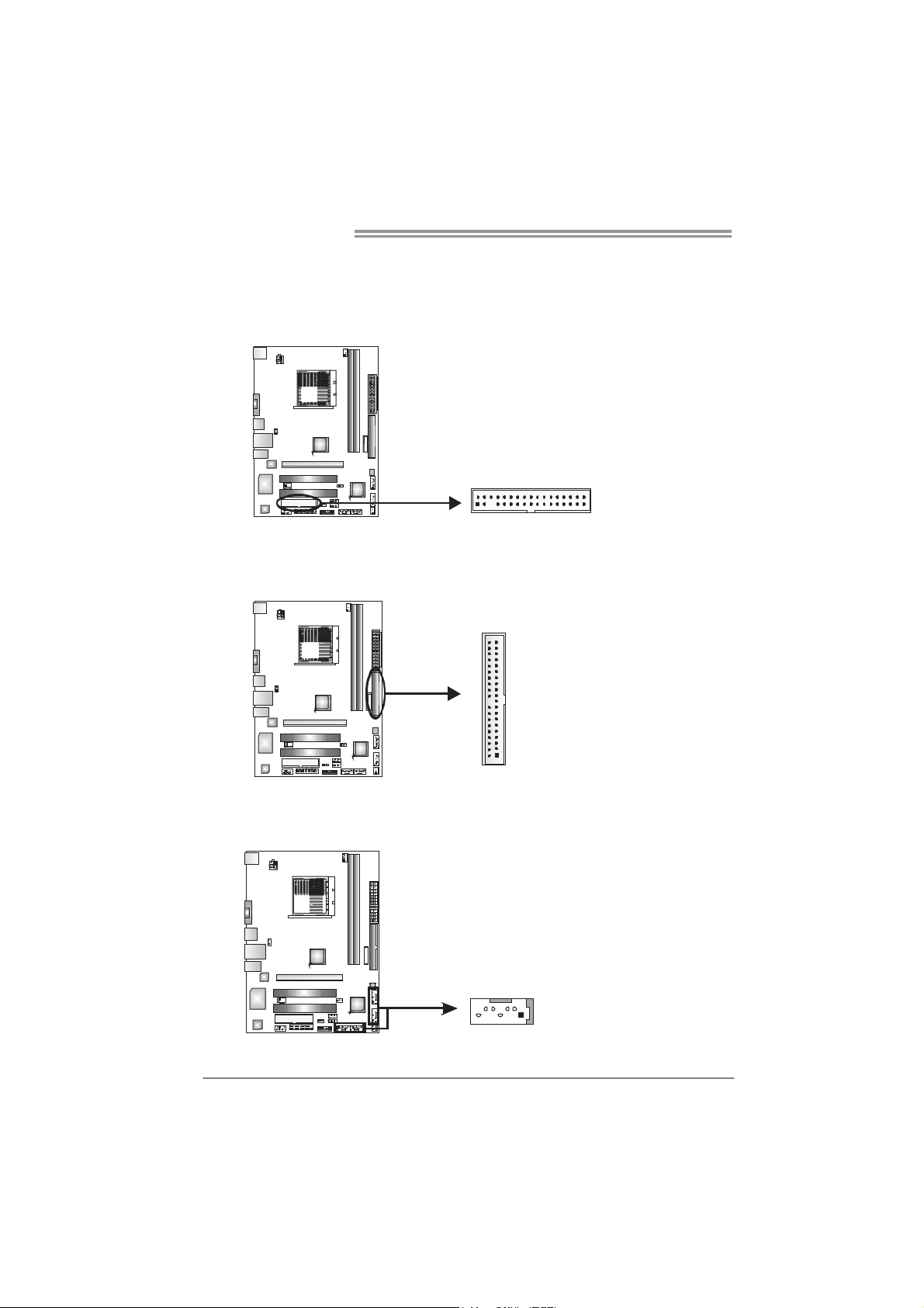
IDE1: Hard Disk Connector
The motherboard has a 32-bit Enhanced PCI IDE Controller that provides PIO
Mode 0~4, Bus Master, and Ultra DMA 33/66/100/133 functionality.
21
3940
SATA1~SATA4: Serial ATA Connectors
The motherboard has a PCI to SATA Controller with 4channels SATA interface, it
satisfies the SATA 2.0 spec and with transfer rate of 3Gb/s.
Pin Assignment
1 Ground
2 TX+
3 TX-
4 Ground
5 RX-
6 RX+
147
SATA1 SATA2
SATA4
SATA3
7 Ground
A740G M2L+/A780LB
11
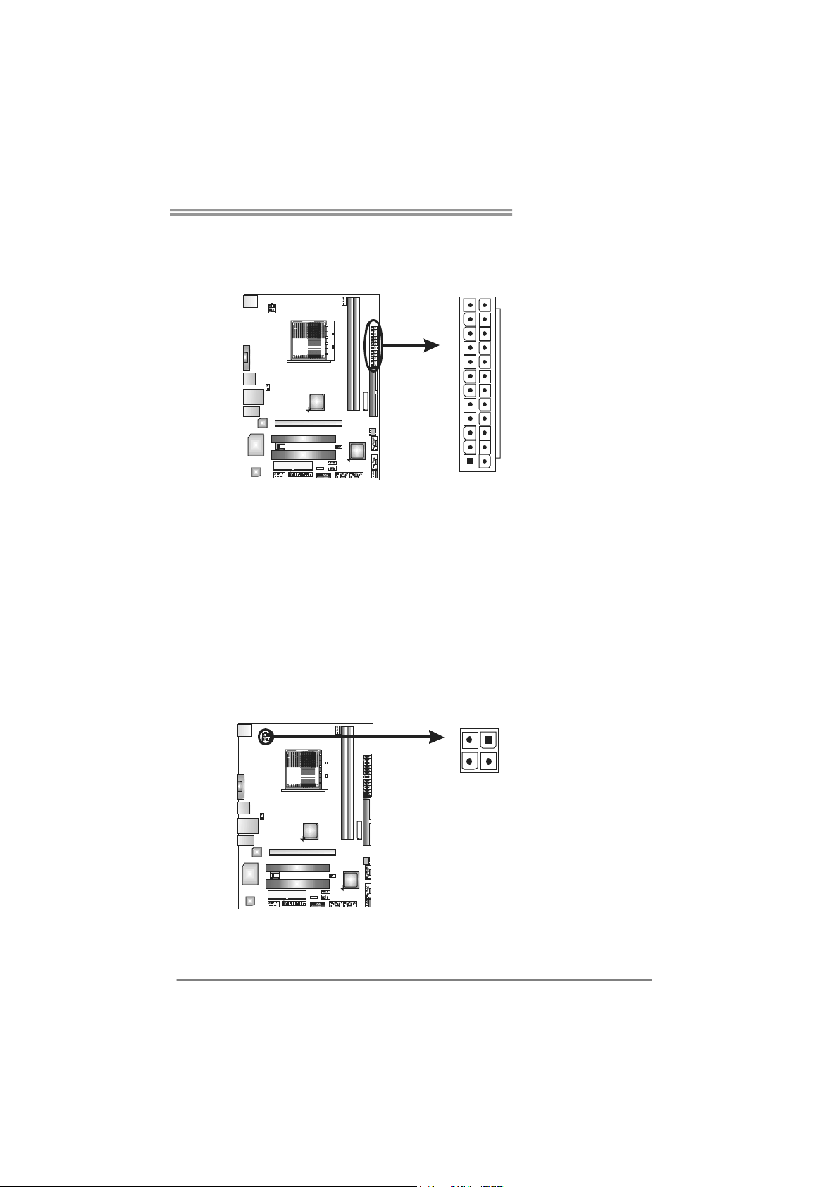
ATXP W R1: AT X Power Source Connector
This connector allows user to connect 24-pin power connector on the ATX
power supply.
1
12
13
24
Pin Assignment Pin Assignment
13 +3.3V 1 +3.3V
14 -12V 2 +3.3V
15 Ground 3 Ground
16 PS_ON 4 +5V
17 Ground 5 Ground
18 Ground 6 +5V
19 Ground 7 Ground
20 NC 8 PW_OK
21 +5V 9 Standby Voltage+5V
22 +5V 10 +12V
23 +5V 11 +12V
24 Ground 12 +3.3V
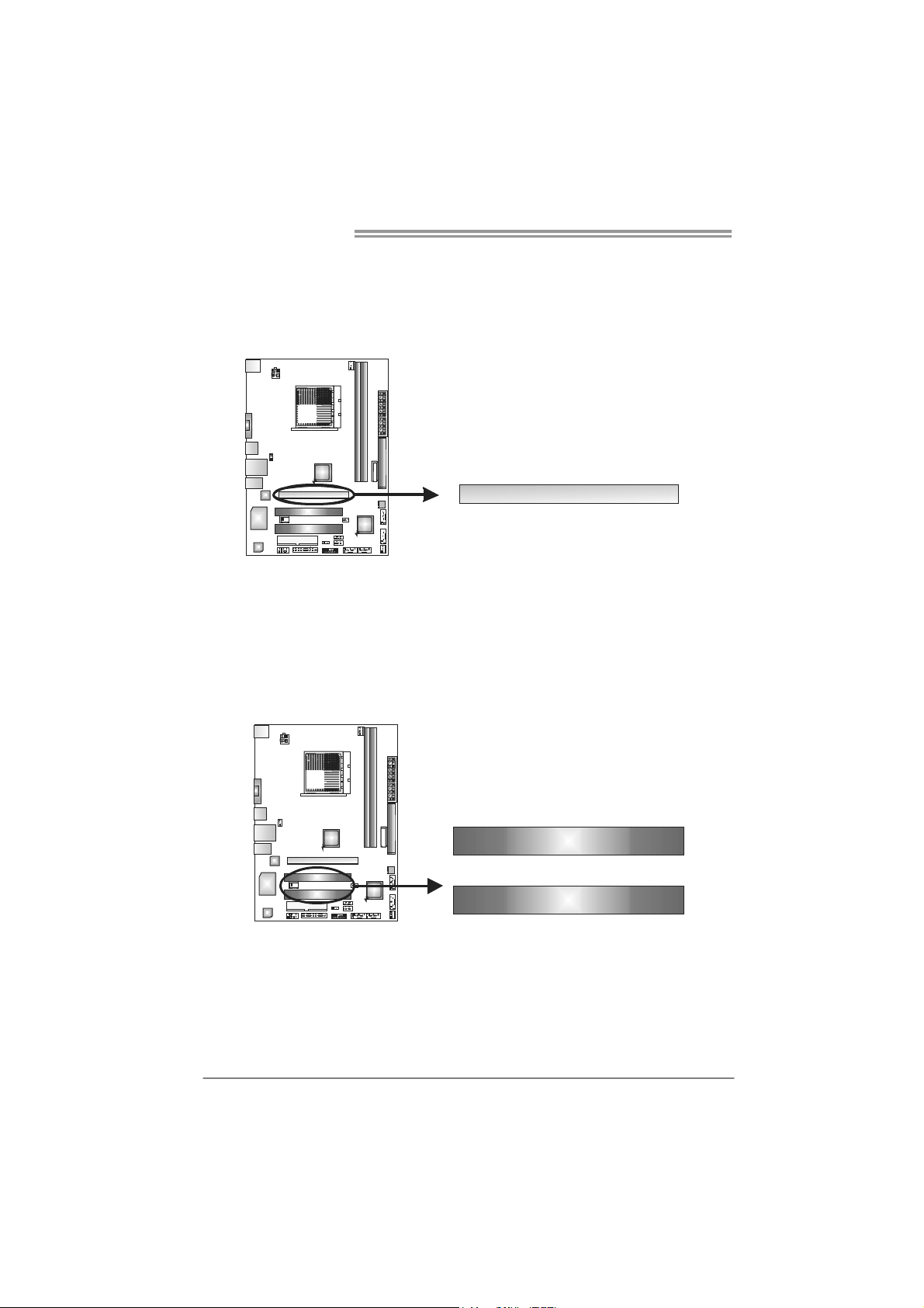
ATXP W R2: AT X Power Source Connector
Connecting this connector provides +12V to CPU power circuit.
Pin
Assignment
1 +12V
2 +12V
3 Ground
34
12
4 Ground
Note:
Before power on the system, please make sure that both ATXPWR1 and ATXPWR2
connectors have been plugged-in.
Motherboard Manual
12
PEX16_1: PCI-Express X16 Slot
- PCI-Express 2.0 compliant.
- Maximum theoretical realized bandwidth of 4GB/s simultaneously per
direction, for an aggregate of 16GB/s totally.
- PCI-Express supports a raw bit-rate of 2.5Gb/s on the data pins.
PEX16_1
PCI1~PCI2: Peripheral Component Interconnect Slots
This motherboard is equipped with 2 standard PCI slots. PCI stands for
Peripheral Component Interconnect, and it is a bus standard for expansion
cards. This PCI slot is designated as 32 bits.
PCI1
PCI2
A740G M2L+/A780LB
13
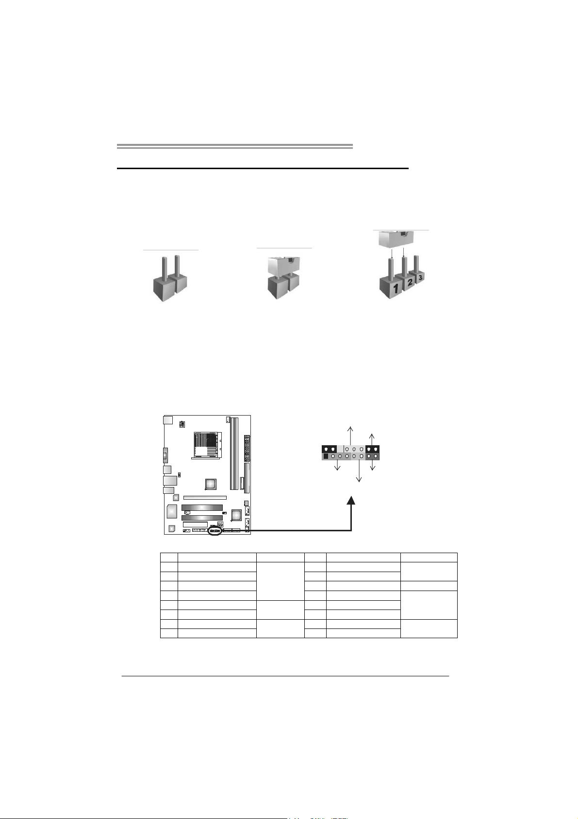
CHAPTER 3: HEADERS & JUMPERS SETUP
3.1 H
OW TO SETUP JUMPERS
The illustration shows how to set up jumpers. When the jumper cap is
placed on pins, the jumper is “close”, if not, that means the jumper is
“open”.
Pin opened Pin closed Pin1-2 closed
3.2 DETAIL SETTINGS
PANEL1: Front Panel Header
This 16-pin connector includes Power-on, Reset, HDD LED, Power LED, and
speaker connection. It allows user to connect the PC case’s front panel switch
functions.
1
8
16
PWR_LED
On/Off
RST
HLED
SPK
++
+
9
-
-
Pin Assignment Function Pin Assignment Function
1 +5V 9 N/A
2 N/A 10 N/A
N/A
3 N/ A 11 N/A N/A
4 Speaker
Speaker
Connector
12 Power LED (+)
5 HDD LED (+) 13 Power LED (+)
6 HDD LED (-)
Hard drive
LED
14 Power LED (-)
Power LED
7 Ground 15 Power button
8 Reset control
Reset button
16 Ground
Power-on button
 Loading...