


P4M890-M7 FE

P4M900-M7 FE/P4M890-M7 FE BIOS Setup
i
BIOS Setup ................................................................................................ 1
1 Main Menu ............................................................................................. 3
2 Standard CMOS Features..................................................................... 6
3 Advanced BIOS Features ...................................................................... 8
4 Advanced Chipset Features................................................................. 16
5 Integrated Peripherals......................................................................... 20
6 Power Management Setup................................................................... 26
7 PnP/PCI Configurations...................................................................... 31
8 PC Health Status .................................................................................. 34
9 Performance Booster Zone.................................................................. 37

P4M900-M7 FE/P4M890-M7 FE
1
BIOS Setup
Introduction
The purpose of this manual is to describe the settings in the Phoenix-Award™
BIOS Setup program on this motherboard. The Setup program allows users to
modify the bas ic system configuration and save these settings to C MOS RAM.
The power of CMOS RAM is supplied by a battery so that it retains the Set up
info rmation when t he power is t urned off.
Basic Input-Output Sys tem ( BIOS) d et ermine s what a computer c an do without
accessing programs from a disk. This system controls most of the input and
outp ut de vices suc h as keyboard, mouse, serial ports and dis k drives. BIOS
activates at the first stage of the booting proc ess, loading and executing the
operating system. Some additional features, s uch as virus and password
protection or chipset fine-tuning options are also included in BIOS.
The rest of this manual will to guide you through the options and settings in
BIOS Setup.
Plug and Play Support
This PHO ENIX-AW ARD BIOS suppo rts t he Plug and Play Version 1. 0A
specification.
EPA Green PC Support
This PHOENIX-AWARD BIOS supports Version 1.03 of the EPA Green PC
specification.
APM Support
This PHOENIX-AWARD BIOS suppo rts Vers ion 1.1& 1. 2 of t he Advanc ed
Power Management (APM) specification. Power management features are
implemented via the System Management Interrupt (SMI). Sleep and Suspend
power management modes are supported. Power to the hard disk drives and
video monito rs can also be managed by this PHOENIX-AWARD BIOS.
ACPI Support
Phoenix-Award ACPI BIOS support Version 1.0b of Advanced Configuration
and Power interface specification (ACPI). It provides ASL code for power
management and device configuration capabilit ies as defined in the ACPI
specification, developed by Microsoft, Intel and Toshiba.

P4M900-M7 FE/P4M890-M7 FE
2
PCI Bus Support
This PHO ENI X-AWARD BIOS a lso s uppo rts Vers ion 2.3 o f the Intel PCI
(Peripheral Component Interconnect) local b us specific atio n.
DRAM Support
DDR2 S DRAM (Double Data Rate S ynchronous DRAM) is supported.
Supported CPUs
This PHOENIX-AWARD BIOS supports the Intel CPU.
Using Setu p
Use the arrow keys to high light items in most of the plac e, press <Enter> to
select, use the <PgUp> and <PgDn> keys to change entries, press <F1> for help
and press <Esc> to quit. The following table p rovides more detail about how to
navigate in t he Setup p rogram by using the keyboard.
Keystroke Function
Up arrow Move to p revio us i tem
Down arrow Move to next i tem
Left arro w Move to the item o n the left (menu bar )
Right arrow Move to t he item o n the ri ght (me nu bar)
Move Enter Move to the item you desired
PgUp key Inc rease the numeric value or make changes
PgDn key Decrease the numeric value or make changes
+ Key Increase the numeric value or make changes
- Key Decrease the numeric value or make c hanges
Esc key Main Menu – Quit and not save changes into CMOS
Status Page Setup Menu and Optio n Page Setup Me nu – Exit
Current page and re turn to Main Menu
F1 key General help o n Setup navigation keys
F5 key Load previous values from CMOS
F7 key Load the optimized defaults
F10 key Save all the CMOS changes and exit
P4M900-M7 FE/P4M890-M7 FE
3
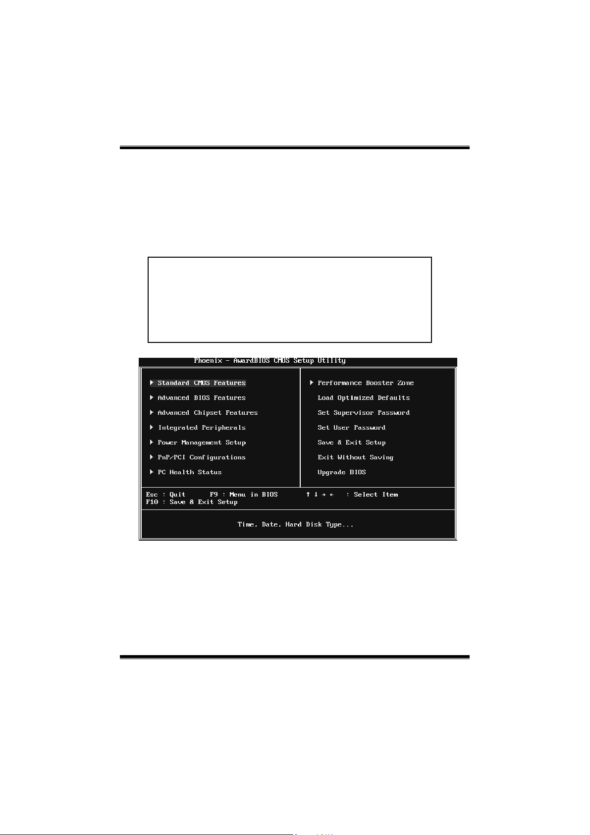
1 Main Menu
Onc e you enter Phoenix-Award BIOS™ CMOS Setup Utility, the Main Menu
will appear o n the screen. The Main Menu allows you to s elect from several
setup functions. Use the arrow keys to select among the items and press <Enter>
to accept and enter the sub-menu.
Figure 1: Main Menu
Stan dar d CMOS Fe atures
This submenu contains industry standard configurable options.
Advanced BIOS Features
This submenu a llows yo u to configure advanced feat ures o f th e BIOS.
!! WARNING !!
For better system performance, the BIOS firmware is being
continuo us ly updated. The BIOS in formatio n describ ed in
this manual (Figure 1, 2, 3, 4, 5, 6, 7, 8, 9) is fo r yo ur
reference only. The actual BIOS information and settings on
board may be slightly different from this manual.

P4M900-M7 FE/P4M890-M7 FE
4
Advanced Chipset Features
This submenu allows you to configure special chipset features.
Integrated Peripherals
This s ub menu allo ws you to configure certain IDE hard d rive optio ns and
Programmed Input/ Output features.
Power Management Setup
This submenu allows you to configure the power management features.
PnP/PCI Configurati ons
This submenu allows you to configure certain “Plug and Play” and PCI options.
PC Health Status
This submenu a llo ws yo u to monitor the hard ware of your syste m.
Performance Booster Zone
This submenu allows you to change CPU Vcore Voltage and CPU/PCI clock.
(However, we suggest you to use the default setting. Changing the voltage and
cloc k imp rop erly may d amage th e CPU or M/B!)
Load Optimized Defaults
This selection allo ws you to reload the BIOS when problem occurs during
system booting sequenc e. These configurations are factory settings optimized
for this system. A confirmation message will be disp layed before defaults are
set.
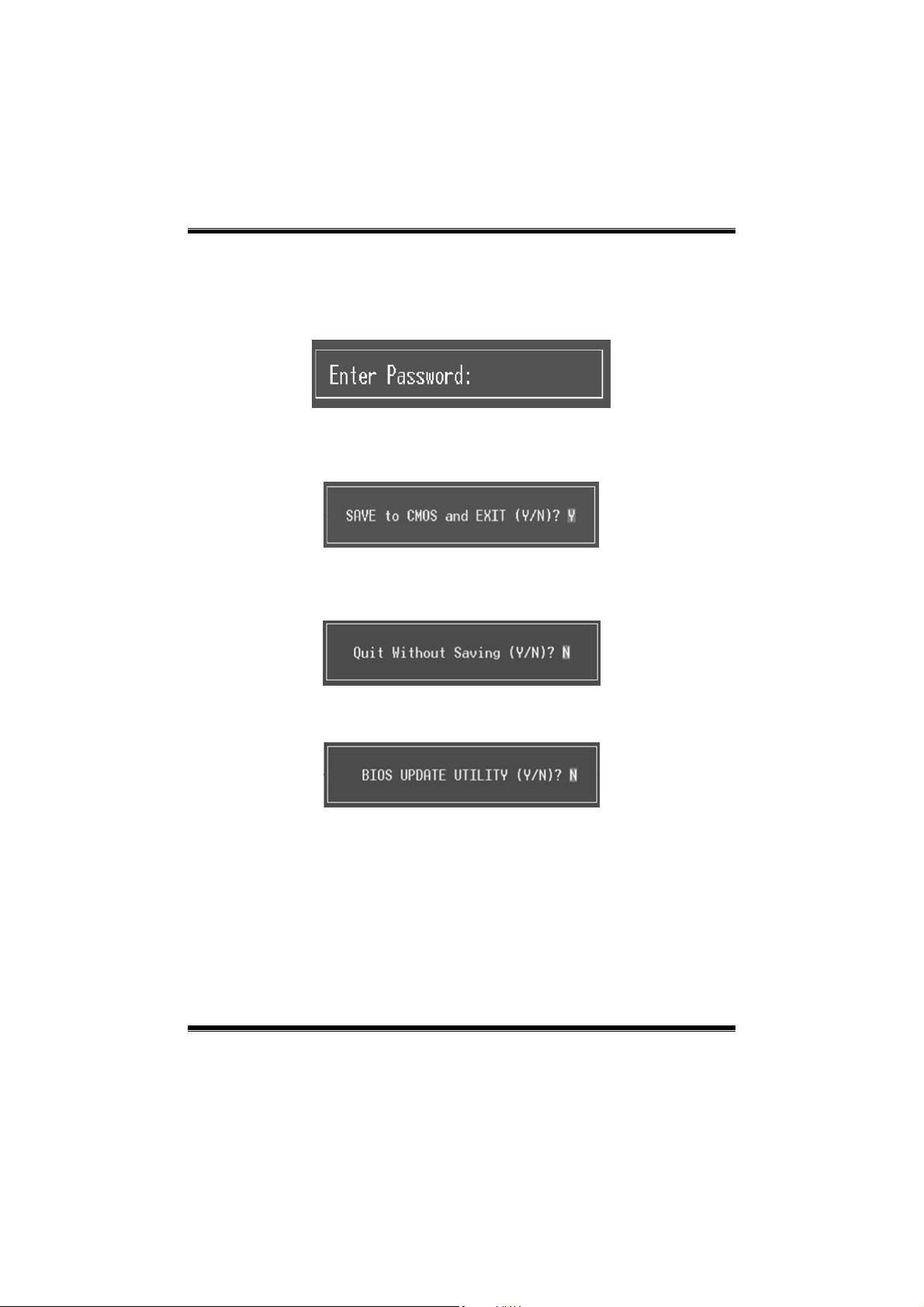
Set Supervisor Password
Setting the sup ervisor password wil l prohibit everyone except the supervisor
from making changes using the CMOS Setup Utility. You will b e prompted with
to ent er a password.
P4M900-M7 FE/P4M890-M7 FE
5
Set User Password
If the Supervisor P ass word is not set, then the User P ass word will function in
the same way as the Supervisor Password. If the Supervisor Password is set and
the User P ass word is set, the “User” wil l o nly be able to view configurations but
will not be able to c hange them.
Save & Exit Setup
Save all configuration c hanges to CMOS (memory) and exit setup. Confirmation
message will be displayed before proceeding.
Exit Without Saving
Abandon all changes made during the current session and exit setup.
Confirmation message will be displayed before proceeding.
Upgrade BIOS
This submenu allows you to upgrade bios.

P4M900-M7 FE/P4M890-M7 FE
6
2 Standard CMOS Features
The items in Standard CMOS Setup Menu are divided into several categories.
Each category includ es no, one or mo re than one set up items. Us e the arrow
keys to highlight the ite m and then use the<P gUp> or <PgDn> keys to se lec t the
value you want in each item.
Figure 2: Standard CMOS Setup
Main Menu Selections
This table shows the items and the available options on the Main Menu.
Item Options Description
Date mm : dd : yy
Set the system date. Note
that the ‘Day’ automatically
changes when you set the
date.
Time hh : mm : ss
Set the system internal
clock.
IDE Channel 0 Master
Options are in its sub
menu.
Press <Enter> to enter the
sub menu of detailed
options
IDE Channel 0 Slave
Options are in its sub
menu.
Press <Enter> to enter the
sub menu of detailed
options.

P4M900-M7 FE/P4M890-M7 FE
7
Item Options Description
IDE Channel 1 Master
Options are in its sub
menu.
Press <Enter> to enter the
sub menu of detailed
options.
IDE Channel 1 Slave
Options are in its sub
menu.
Press <Enter> to enter the
sub menu of detailed
options.
Drive A
Drive B
360K, 5.25 in
1.2M, 5.25 in
720K, 3.5 in
1.44M, 3.5 in
2.88M, 3.5 in
None
Select the type of floppy
disk drive installed in your
system.
Halt On
All Errors
No Errors
All, but Keyboard
All, but Diskette
All, but Disk/ Key
Select the situation in which
you want the BIOS to stop
the POST process and
notify you.
Base Memory N/A
Displays the amount of
conventional memory
detected during boot up.
Extended Memory N/A
Displays the amount of
extended memory detected
during boot up.
Total Memory N/A
Displays the total memory
available in the system.
P4M900-M7 FE/P4M890-M7 FE
8
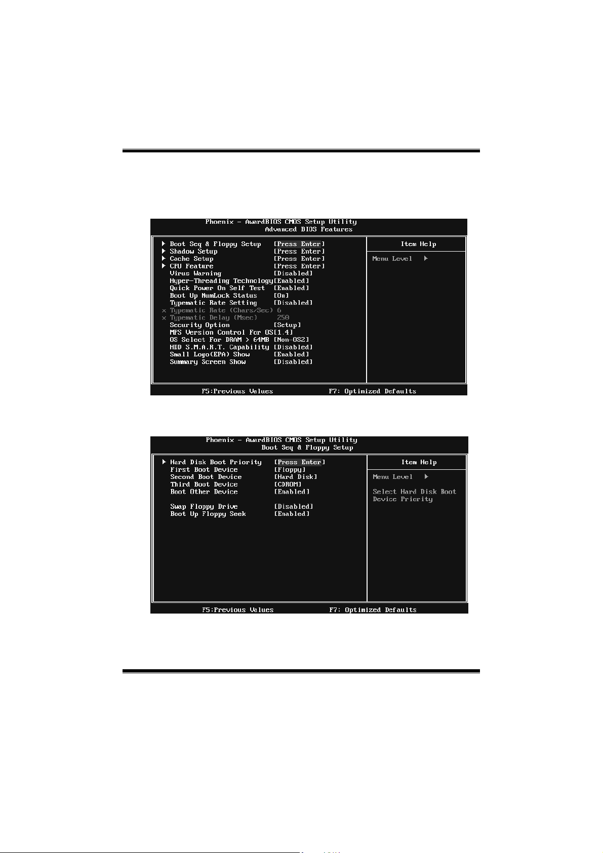
3 Advanced BIOS Features
Figure 3: Advanced BIOS Setup
Boot Seq & Floppy Setup
This item allows you to setup boot sequence & Floppy.
P4M900-M7 FE/P4M890-M7 FE
9
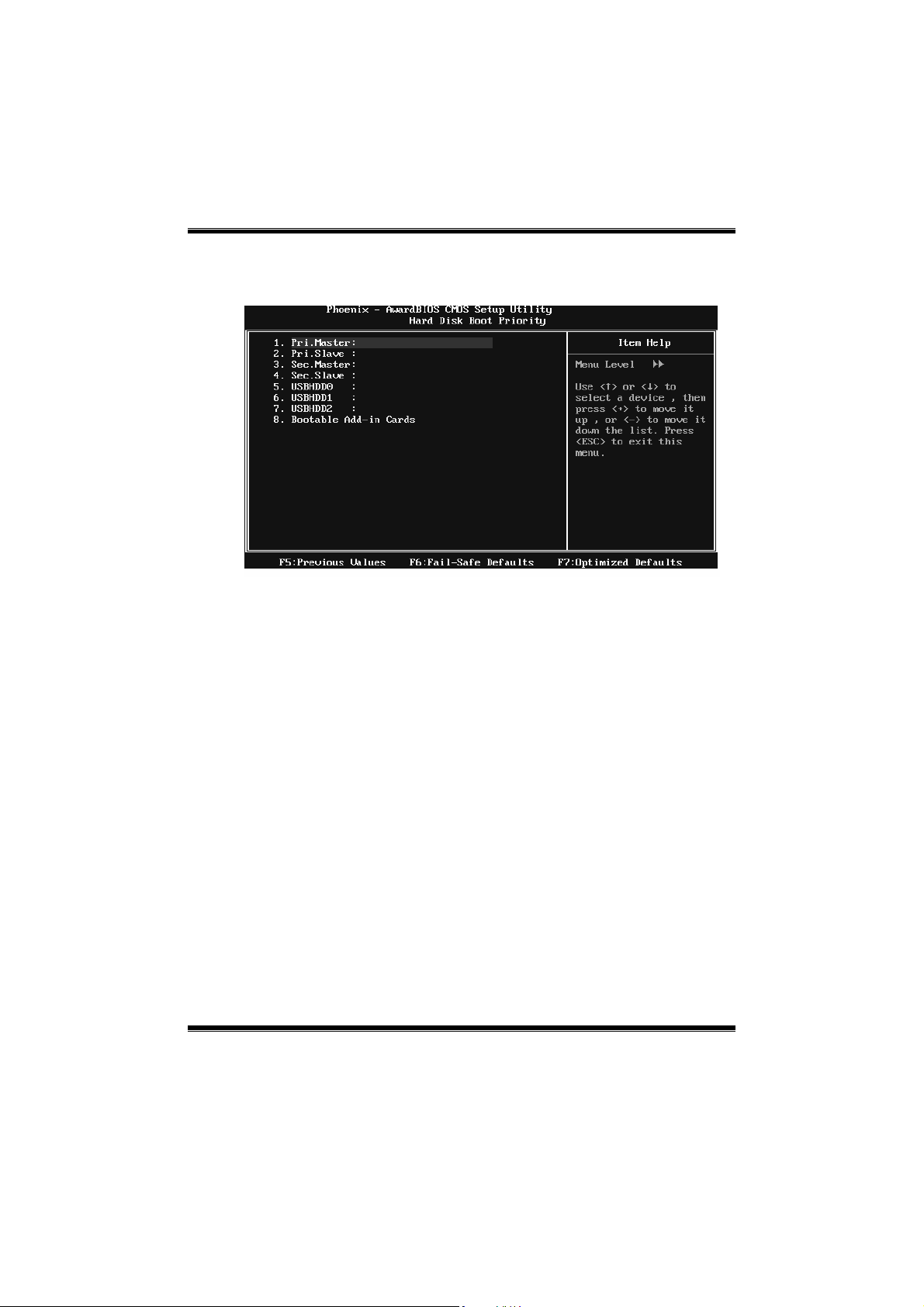
Hard Disk Boot Priority
The BIOS will attempt to arrange the Hard Disk boot sequence automatically.
You can change the Hard Disk booting sequence here.
The Choices: Pri. Master, Pri. Slave, Sec. Master, Sec. Slave, USB HDD0, USB
HDD1, US B HDD2, and Bootable Add-in Cards.
First/Second/Third Boot Device
The BIOS will attempt to load the operating system in this order.
The Choices: Floppy, LS120, Hard Disk, CDROM, ZIP100, USB-FDD,
USB-ZIP, USB-CDROM, LAN, Disabled.
Boot Other Device
When enabled, BIOS will try to load the operating system from other device
when it failed to load from the three devices above.
The Choices: Enabled (default), Disab led
Swap Floppy Drive
For systems with two floppy drives, this option allows you to swap logical
drive assignments.
The Choices: Disabled (default), Enabled.
P4M900-M7 FE/P4M890-M7 FE
10
Boot Up Floppy Seek
When enabled, System will test the floppy drives to determine if they have 40
or 80 tracks during boot up. Disabling this option reduces the time it takes to
boot-up.
The Choices: Enabled (default), Disabled.
Shadow Setup
This item allows you to setup c ac he & s hadow setup.
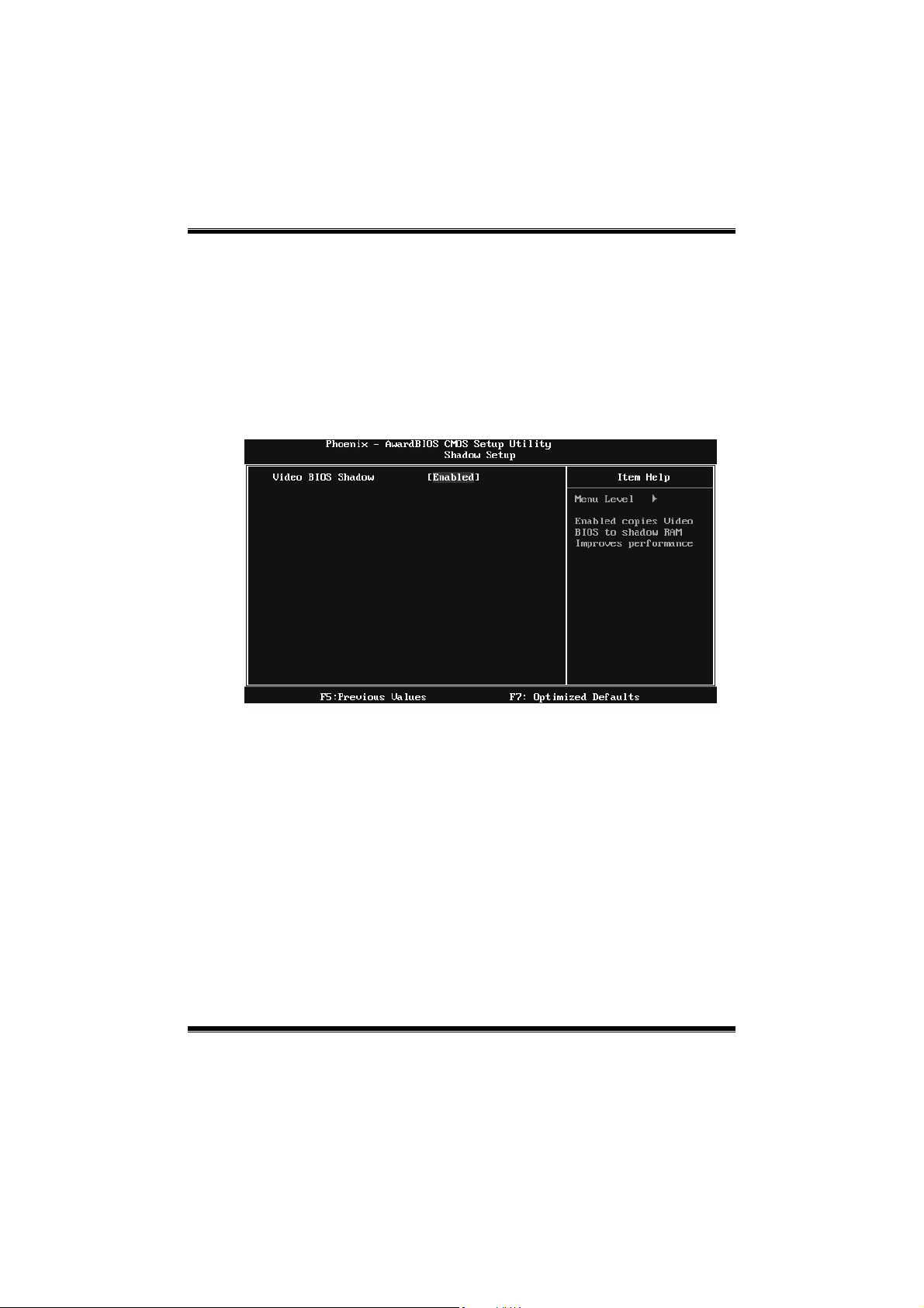
Figure 3.2: Shadow Setup
Video BIOS Shadow
Determines whether video BIOS will be copied to RAM for faster execution or
not.
Enable d (default) Optional ROM is enabled.
Disabled Optional ROM is disabled.
P4M900-M7 FE/P4M890-M7 FE
11
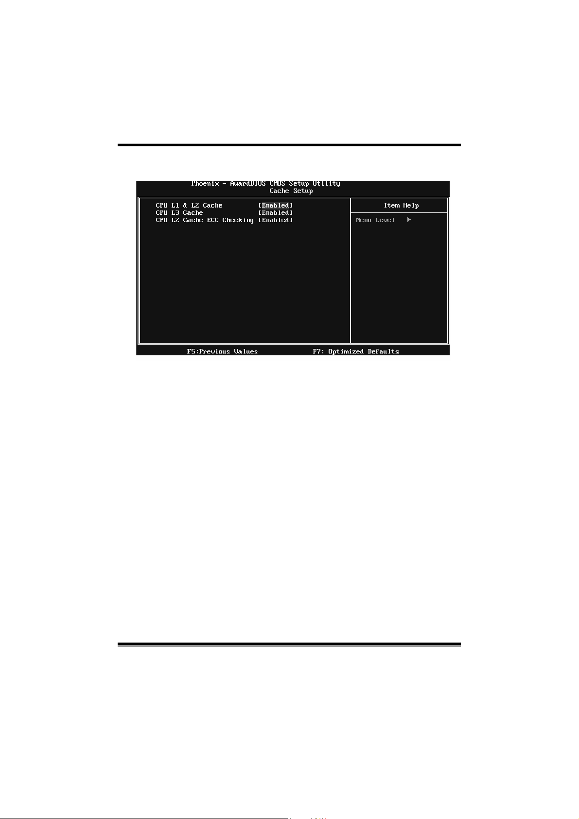
Cache Setup
CPU L1 & L2 Cache
Depending on the CPU/chipset in use, you may be able to increase memory
ac cess tim e with this opt ion .
Enable d (default) Enable cache.
Disabled Disable cache.
CPU L3 Cache
Depending on the CPU/chipset in use, you may be able to increase memory
ac cess tim e with this opt ion .
Enable d (default) Enable cache.
Disabled Disab le cache.
CPU L2 Cache ECC Checking
This item allows you to enable/disable CPU L2 Cache ECC Checking.
The Choices: Enabled (default), Disabled.
P4M900-M7 FE/P4M890-M7 FE
12
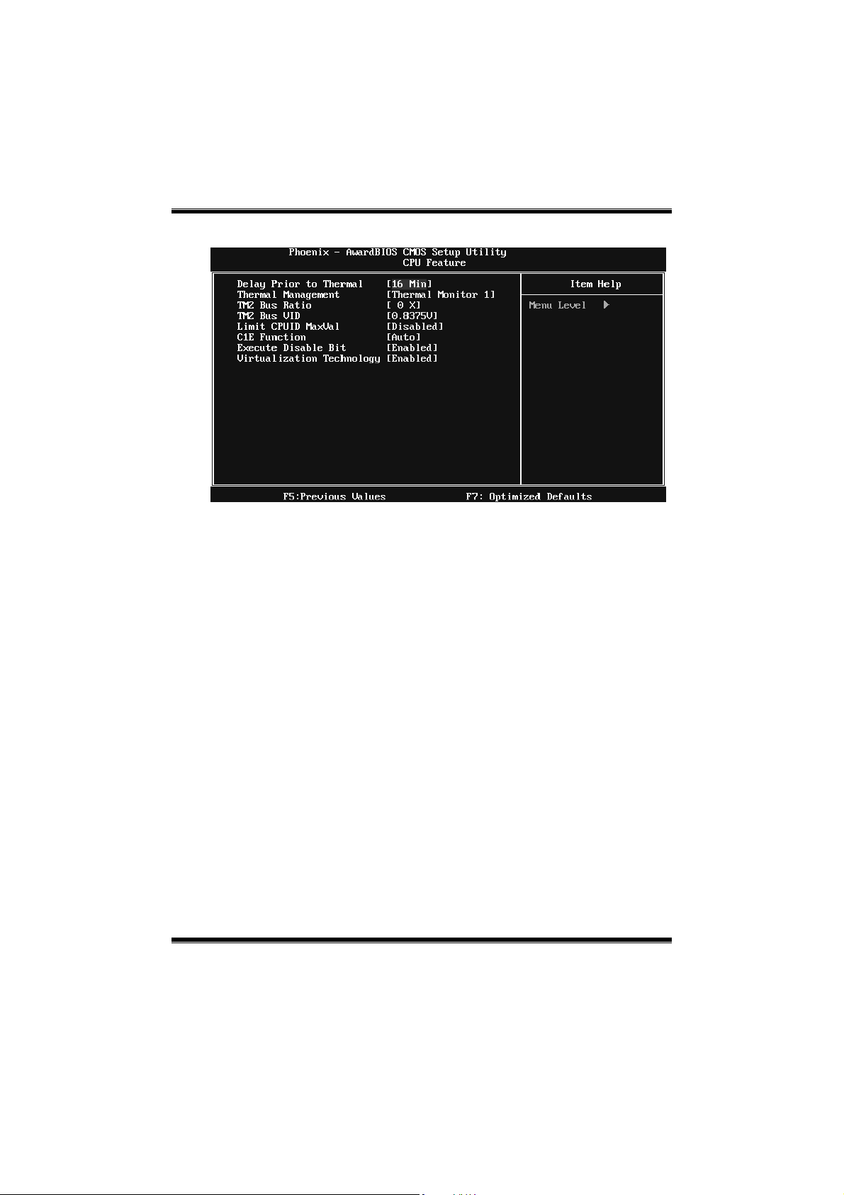
CPU Feature
Delay Prior to Thermal
Set this item to enable the CPU Thermal function to engage after the specified
time.
The Choices: 4 Min, 8 Min, 16Min (default), 32 Min.
Thermal Management
This option allows you to select the way to control the “Thermal Management.”
The Choices: Thermal Monitor 1 (default), Thermal Monitor 2.
TM2 Bus Ratio
This option represents the frequency (bus ratio) of the throttled performance
st ate t hat w ill be init iated whe n the o n-die sensor dete cts temper atu re increa se.
Min= 0, Max= 255 ; Key in a DEC number.
The Choices: 0 X (default)
TM2 Bus VID
This option represents the voltage of the throttled performance state that will be
initia ted when the o n-die sensor detects temp eratur e increase.
The Choices: 0.8375V (default), 0.8375-1.6000.
 Loading...