


 Loading...
P4M80-M4
FCC Information and Copyright
This equipment has been tested and found to comply with the limits of a Class B digital device, pursuant to Part 15 of the FCC Rules. These limits are designed to provide reasonable protection against harmful interference in a residential installation. This equipment generates, uses and can radiate radio frequency energy and, if not installed and used in accordance with the instructions, may cause harmful interference to radio communications. There is no guarantee that interference will not occur in a particular installation.
The vendor makes no representations or warranties with respect to the contents here and specially disclaims any implied warranties of merchantability or fitness for any purpose. Further the vendor reserves the right to revise this publication and to make changes to the contents here without obligation to notify any party beforehand.
Duplication of this publication, in part or in whole, is not allowed without first obtaining the vendor’s approval in writing.
The content of this user’s manual is subject to be changed without notice and we will not be responsible for any mistakes found in this user’s manual. All the brand and product names are trademarks of their respective companies.
i

Table of Contents
Chapter 1: Introduction .......................................................... |
1 |
|
1.1 |
Motherboard Features .......................................................... |
1 |
1.2 |
Package Checklist ................................................................ |
4 |
1.3 |
Layout and Components....................................................... |
5 |
Chapter 2: Hardware Installation ........................................... |
6 |
|
2.1 |
Installing Central Processing Unit (CPU).............................. |
6 |
2.2 |
FAN Headers ........................................................................ |
7 |
2.3 |
Installing System Memory..................................................... |
8 |
2.4 |
Connectors and Slots............................................................ |
9 |
Chapter 3: Headers & Jumpers Setup................................. |
12 |
|
3.1 |
How to Setup Jumpers ....................................................... |
12 |
3.2 |
Detail Settings..................................................................... |
12 |
Chapter 4: Useful Help.......................................................... |
19 |
|
4.1 |
Award BIOS Beep Code ..................................................... |
19 |
4.2 |
Extra Information................................................................. |
19 |
4.3 |
Troubleshooting .................................................................. |
21 |
Chapter 5: WarpSpeeder™................................................... |
22 |
|
5.1 |
Introduction ......................................................................... |
22 |
5.2 |
System Requirement .......................................................... |
22 |
5.3 |
Installation........................................................................... |
23 |
5.4 |
[WarpSpeeder™] includes 1 tray icon and 5 panels........... |
24 |
ii
P4M80-M4
CHAPTER 1: INTRODUCTION
1.1MOTHERBOARD FEATURES
A. Hardware
CPU
Supports Socket 478.
Supports Intel Pentium 4 processor up to 3.4GHz.
Supports Intel Celeron/Celeron D processor.
Supports Intel Pentium 4 Northwood/Prescott CPU.
Do not support Williamate CPU.
Front Side Bus at 400/533/800 MHz.
Chipset
North Bridge: VIA P4M800.
South Bridge: VIA VT8237R.
Dimensions
ATX Form Factor: 20.2cm(W) x 24.4cm (L)
Operating System Supporting
Supports Windows 98SE, Windows NT, Windows 2000, Windows ME, Windows XP, Red-Hat Linux, and UNIX series.
System Memory
Supports up to 2 DDR devices.
Supports 266/333/400MHz DDR devices.
Maximum memory size is up to 2GB. (Following table is only for reference.)
DIMM Socket |
DDR Module |
Total Memory |
|
Location |
Size |
||
|
|||
DIMM1 |
128MB/256MB/512MB/1GB *1 |
Max is 2GB. |
|
DIMM2 |
128MB/256MB/512MB/1GB *1 |
||
|
Serial ATA
Controller integrated in SB VT8237R.
Supports RAID 0 and RAID 1 functions.
Supports 2 Serial ATA (SATA) devices.
-Compliant with SATA Version 1.0 specification.
-Data transfer rate up to 150 MB/s.
1

P4M80-M4
Super I/O
Chip: ITE IT8705AF.
Provides the most commonly used legacy Super I/O functionality.
Environment Control initiatives:
H/W Monitor
Fan Speed Controller
ITE's "Smart Guardian" function
On Board IDE
Two on-board connectors support 4 devices.
Supports PIO Mode 0~4.
Supports Ultra DMA 33/66/100/133 Bus Master Mode.
On Board AC’97 Sound Codec
Chip: REALTEK ALC655.
Support 6 channels.
Supports SPDIF out function.
Compliant with AC’97 Version 2.3 specification.
10/100 LAN
Chip: VIA VT6103L.
Supports 10/100 Mb/s auto-negotiation operation.
Half/Full duplex capability.
Supports ACPI and PCI power management.
Expansion Slots
Three 32bit PCI bus master slots. One AGP 4x/8x compatible slot. One CNR slot.
2

P4M80-M4
Internal On-board I/O Connectors and Headers
1 front panel header supports front panel facilities.
1 CD-in connector supports 1 CD-ROM audio-in device.
1 front audio header supports front panel audio-out function.
1 SPDIF-out connector supports digital audio-out function.
1 chassis open header supports PC case-opened warning function.
1 Floppy port supports 2 FDD with 360K, 720K, 1.2M, 1.44M and 2.88Mbytes.
2 IDE connectors support 4 hard disk devices.
2 Serial ATA connectors support 2 SATA devices.
2 USB headers support 4 USB 2.0 ports at front panel.
Back Panel I/O Connectors
4 USB 2.0 ports.
1 VGA port.
1 Serial port.
1 Printer port.
1 RJ-45 LAN jack.
1 PS/2 Mouse port.
1 PS/2 Keyboard port.
1 vertical audio port including 1 line-in connector, 1 line-out connector, and 1 MIC-in connector.
PS/2 |
Printer port |
Mouse |
VGA1
COM1
PS/2
Keyboard
LAN |
USB x2 |
USB x2 |
Line In/
Surround
Line Out
Mic In 1/
Bass/Center
3
P4M80-M4
B. BIOS & Software
BIOS
Award legal BIOS.
Supports APM1.2.
Supports ACPI
Supports USB Function.
Software
Supports Warpspeeder™, 9th Touch™, WINFLASHER™ and FLASHER™.
1.2PACKAGE CHECKLIST
FDD Cable X 1
HDD Cable X 1
User’s Manual X 1
Fully Setup Driver CD X 1
USB 2.0 Cable X1 (optional)
Serial ATA Cable X 2 (optional)
SPDIF out Cable X 1 (optional)
Rear I/O Panel for ATX Case X 1
4

P4M80-M4
1.3LAYOUT AND COMPONENTS
JKBMS1 |
|
|
|
PU |
JCFAN1 |
|
|
|
|
Socket 478 |
|
JC |
|
|
OM1 |
|
|
|
CPU1 |
|
JPRNT |
|
|
JVGA1 |
DIMM1 |
DIMM2 |
|
JATXPWR2 |
|
JUSB1 |
JUSBV1 |
|
(optional) |
|
|
JUSBLAN1 |
P4M800 |
IDE1 |
|
Super |
|
|
I/O |
|
JAUDIO |
|
|
 JATXPWR1
IDE2
|
BIOS |
|
AGP1 |
|
|
|
|
LAN |
|
PCI1 |
BAT1 |
|
|
|
|
|
JUSB3 |
|
|
JAUDIO1 |
|
PCI2 |
VT8237R |
JSATA2 |
|
|
|
||||
|
JUSB4 |
|
|
||
JCDIN1 |
|
|
|
|
|
JSPDIFO1 |
|
|
|
JSATA1 |
|
JAUX1 |
|
JUSBV2(optional) |
|
||
|
|
|
|||
(optional) |
|
|
|
|
|
|
|
PCI3 |
|
|
|
|
|
|
|
JCMOS1 |
|
Codec |
CNR1 |
|
FDD1 |
JCI1 |
|
|
|
JPANEL1 |
IR (optional) |
||
|
|
|
JSFAN1 |
||
Note: ■ represents the 1st pin.
5
P4M80-M4
CHAPTER 2: HARDWARE INSTALLATION
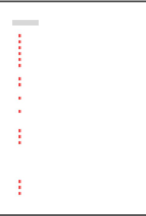
2.1INSTALLING CENTRAL PROCESSING UNIT (CPU)
PU |
Step 1: Pull the lever sideways away from the socket and then raise the lever up to a 90-degree angle.
Step 2: Look for the white dot/cut edge. The white dot/cut edge should point wards the lever pivot. The CPU will fit only in the correct orientation.
Step 3: Hold the CPU down firmly, and then close the lever to complete the installation.
Step 4: Put the CPU Fan on the CPU and buckle it. Connect the CPU FAN power cable to the JCFAN1. This completes the installation.
6

P4M80-M4
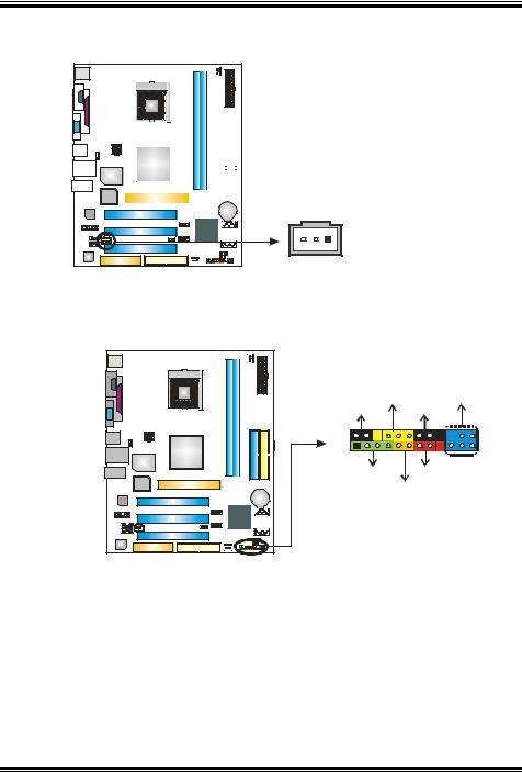
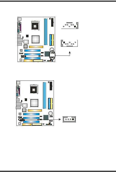
2.2FAN HEADERS
These fan headers support cooling-fans built in the computer. The fan cable and connector may be different according to the fan manufacturer. Connect the fan cable to the connector while matching the black wire to pin#1.
JCFAN1: CPU Fan Header
JSFAN1: System Fan Header
PU |
Note: |
3
1
JCFAN1 Pin Assignment
1Ground
2+12V
3FAN RPM rate sense
JSFAN1
3 |
1 |
The JCFAN1 and JSFAN1 support 3-pin head connector. When connecting with wires onto connectors, please note that the red wire is the positive and should be connected to pin#2, and the black wire is Ground and should be connected to GND.
7
P4M80-M4
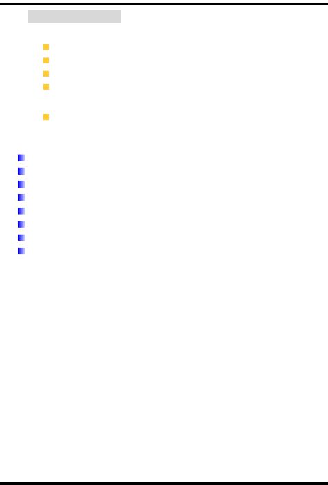
2.3INSTALLING SYSTEM MEMORY
PU
DIMM1DIMM2
1.Unlock a DIMM slot by pressing the retaining clips outward. Align a DIMM on the slot such that the notch on the DIMM matches the break on the Slot.
2.Insert the DIMM vertically and firmly into the slot until the retaining chip snap back in place and the DIMM is properly seated.
8
P4M80-M4
2.4CONNECTORS AND SLOTS
FDD1: Floppy Disk Connector
The motherboard provides a standard floppy disk connector that supports 360K, 720K, 1.2M, 1.44M and 2.88M floppy disk types. This connector supports the provided floppy drive ribbon cables.
PU |
2 |
34 |
1 |
33 |
IDE1/IDE2: Hard Disk Connectors
The motherboard has a 32-bit Enhanced PCI IDE Controller that provides PIO Mode 0~4, Bus Master, and Ultra DMA 33/66/100/133 functionality. It has two HDD connectors IDE1 (primary) and IDE2 (secondary).
The IDE connectors can connect a master and a slave drive, so you can connect up to four hard disk drives. The first hard drive should always be connected to IDE1.
PU |
|
IDE1 |
|
40 |
39 |
2 |
1 |
|
IDE2 |
9 |
|

P4M80-M4
PCI1~PCI3: Peripheral Component Interconnect Slots
This motherboard is equipped with 3 standard PCI slots. PCI stands for Peripheral Component Interconnect, and it is a bus standard for expansion cards. This PCI slot is designated as 32 bits.
PU |
PCI1
PCI2
PCI3
AGP1: Accelerated Graphics Port Slot
Your monitor will attach directly to that video card. This motherboard supports video cards for PCI slots, but it is also equipped with an Accelerated Graphics Port (AGP). An AGP card will take advantage of AGP technology for improved video efficiency and performance, especially with 3D graphics.
PU |
10

P4M80-M4
CNR1: Communication Network Riser Slot
The CNR specification is an open Industry Standard Architecture, and it defines a hardware scalable riser card interface, which supports modem only.
PU |
11

P4M80-M4
CHAPTER 3: HEADERS & JUMPERS SETUP
3.1HOW TO SETUP JUMPERS
The illustration shows how to set up jumpers. When the jumper cap is placed on pins, the jumper is “close”, if not, that means the jumper is “open”.
Pin opened |
Pin closed |
Pin1-2 closed |
3.2DETAIL SETTINGS
JATXPWR1: ATX Power Connector
This connector allows user to connect 20-pin power connector on the ATX power supply.
PU |
|
|
Pin |
Assignment |
|
|
|
1 |
+3.3V |
|
|
|
2 |
+3.3V |
|
|
|
3 |
Ground |
|
|
|
4 |
+5V |
|
12 |
24 |
5 |
Ground |
|
|
|
6 |
+5V |
|
|
|
7 |
Ground |
|
|
|
8 |
PW_OK |
|
|
|
9 |
Standby |
|
|
|
|
Voltage +5V |
|
|
|
10 |
+12V |
|
|
|
11 |
+3.3V |
|
|
|
12 |
-12V |
|
|
|
13 |
Ground |
|
1 |
13 |
14 |
PS_ON |
|
15 |
Ground |
|||
|
|
|||
|
|
16 |
Ground |
|
|
|
17 |
Ground |
|
|
|
18 |
-5V |
|
|
|
19 |
+5V |
|
|
|
20 |
+5V |
12
P4M80-M4
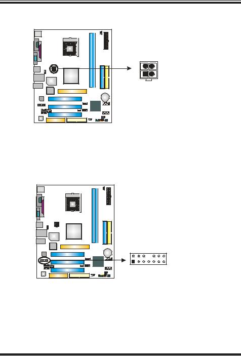
JATXPWR2: ATX Power Connector
By connecting this connector, it will provide +12V to CPU power circuit.
PU |
|
|
Pin |
Assignment |
3 |
4 |
1 |
+12V |
2 |
+12V |
||
1 |
2 |
3 |
Ground |
|
|
4 |
Ground |
JAUDIO1: Front Panel Audio Header
This header allows user to connect the front audio output cable with the PC front panel. It will disable the output on back panel audio connectors.
PU |
|
|
Pin |
Assignment |
|
|
1 |
Mic in/center |
|
|
2 |
Ground |
|
|
3 |
Mic power/Bass |
|
|
4 |
Audio power |
|
|
5 |
Right line |
|
|
|
out/Speaker out |
|
|
|
Right |
|
|
6 |
Right line |
|
|
|
out/Speaker out |
|
|
|
Right |
|
|
7 |
Reserved |
|
|
8 |
Key |
|
|
9 |
Left line |
|
|
|
out/Speaker out |
|
|
|
Left |
2 |
14 |
10 |
Left line |
|
|
|
out/Speaker out |
|
|
|
Left |
1 |
13 |
11 |
Right line in/Rear |
|
|
|
speaker Right |
|
|
12 |
Right line in/Rear |
|
|
|
speaker Right |
|
|
13 |
Left line in/Rear |
|
|
|
speaker Left |
|
|
14 |
Left line in/Rear |
|
|
|
speaker Left |
13
P4M80-M4
JSPDIFO1: Digital Audio-out Connector
This connector allows user to connect the PCI bracket SPDIF output header.
PU
|
|
|
|
|
|
|
|
|
|
|
|
|
Pin |
Assignment |
|
|
|
|
|
|
|
|
|
|
|
|
|
||
|
|
|
|
|
|
|
|
|
|
|
|
|
||
|
|
|
|
|
|
|
|
|
|
|
|
|
||
|
|
|
|
|
|
|
|
|
|
|
|
|||
|
|
|
|
|
|
|
|
|
|
|
|
|
1 |
+5V |
|
|
|
|
|
|
|
|
|
|
|
|
|
||
|
|
|
|
|
|
|
|
|
|
|
||||
|
|
|
|
|
|
|
|
|
|
|
|
|
2 |
SPDIF_OUT |
|
|
|
|
|
|
|
|
|
|
|
||||
|
|
|
|
|
|
|
|
|
|
|
|
|
3 |
Ground |
|
|
|
|
|
|
|
|
|
|
|
|
|
||
|
|
|
|
|
|
|
|
|
|
|
|
|
||
|
|
|
|
|
|
|
|
|
|
|
||||
|
|
|
|
|
|
|
|
|
|
|
|
|
|
|
|
|
|
|
|
|
|
|
|
|
|
|
|
|
|
3 |
1 |
JPANEL1: Front Panel Header
This 24-pin connector includes Power-on, Reset, HDD LED, Power LED, Sleep button, speaker and IrDA Connection. It allows user to connect the PC case’s front panel switch functions.
PU |
|
PWR_LED |
IR(optional) |
|
|
SLP |
On/Off |
|
2 |
+ + - |
24 |
|
|
|
||
1 |
+ |
- |
23 |
|
|
||
|
SPK |
RST |
|
|
HLED |
|
|
Pin |
Assignment |
Function |
Pin |
Assignment |
Function |
|
1 |
+5V |
|
2 |
Sleep control |
Sleep button |
|
3 |
N/A |
Speaker |
4 |
Ground |
||
|
||||||
5 |
N/A |
Connector |
6 |
N/A |
N/A |
|
7 |
Speaker |
|
8 |
Power LED (+) |
|
|
9 |
HDD LED (+) |
Hard drive LED |
10 |
Power LED (+) |
Power LED |
|
11 |
HDD LED (-) |
12 |
Power LED (-) |
|
||
|
|
|||||
13 |
Ground |
Reset button |
14 |
Power button |
Power-on button |
|
15 |
Reset control |
16 |
Ground |
|||
|
|
|||||
17 |
N/A |
|
18 |
Key |
|
|
19 |
N/A |
IrDA Connector |
20 |
Key |
IrDA Connector |
|
21 |
+5V |
22 |
Ground |
|||
(optional) |
(optional) |
|||||
23 |
IRTX |
24 |
IRRX |
|||
|
|
14
P4M80-M4
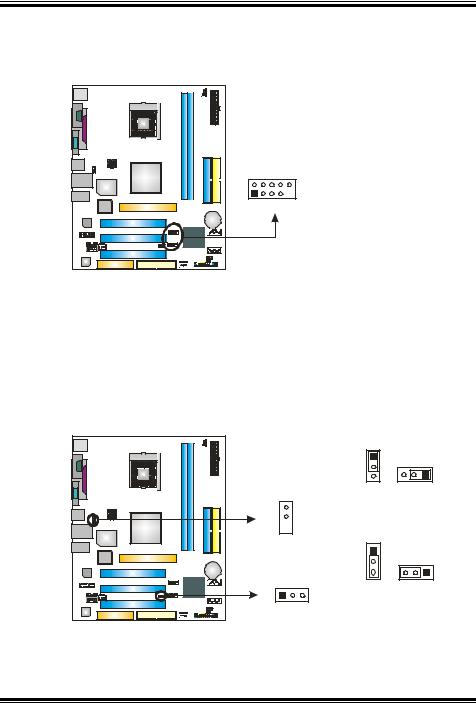
JUSB3/JUSB4: Front USB Headers
This motherboard provides 2 USB 2.0 headers, which allows user to connect additional USB cable on the PC front panel, and also can be connected with internal USB devices, like USB card reader.
PU |
|
|
|
Pin |
Assignment |
|
|
|
|
1 |
+5V (fused) |
|
|
|
|
2 |
+5V (fused) |
|
|
|
|
3 |
USB- |
|
|
|
JUSB3 |
4 |
USB- |
|
2 |
10 |
5 |
USB+ |
||
|
|
|
6 |
USB+ |
|
1 |
9 |
JUSB4 |
7 |
Ground |
|
8 |
Ground |
||||
|
|
|
|||
|
|
|
9 |
Key |
|
|
|
|
10 |
NC |
JUSBV1/JUSBV2: Power Source Headers for USB Ports (optional, Ver. 1.0 only)
Pin 1-2 Close:
JUSBV1: +5V for USB ports at JUSB1 and JUSBLAN1. JUSBV2: +5V for USB ports at front panel (JUSB2/JUSB3).
Pin 2-3 Close:
JUSBV1: USB ports at JUSB1 and JUSBLAN1 are powered by +5V standby voltage.
JUSBV2: USB ports at front panel (JUSB2/JUSB3) are powered by +5V standby voltage.
PU |
|
1 |
|
|
|
3 |
1 |
|
|
3 |
|
|
JUSBV1 |
Pin 1-2 close (Default) |
|
|
3 |
||
|
|
|
|
 1
1
|
|
1 |
|
|
|
3 |
1 |
JUSBV2 |
3 |
|
|
|
|
||
1 |
3 |
Pin 2-3 close |
|
|
|
||
Note:
In order to support this function “Power-On system via USB device,” “JUSBV1/ JUSBV2” jumper cap should be placed on Pin 2-3 individually.
15
P4M80-M4
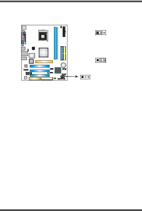
JCMOS1: Clear CMOS Header
By placing the jumper on pin2-3, it allows user to restore the BIOS safe setting and the CMOS data, please carefully follow the procedures to avoid damaging the motherboard.
PU |
|
1 |
3 |
|
|
Pin 1-2 Close: |
|
|
|
Normal Operation (default). |
|
|
|
1 |
3 |
|
|
Pin 2-3 Close: |
|
1 |
3 |
Clear CMOS data. |
|
|
|
||
Clear CMOS Procedures:
1.Remove AC power line.
2.Set the jumper to “Pin 2-3 close”.
3.Wait for five seconds.
4.Set the jumper to “Pin 1-2 close”.
5.Power on the AC.
6.Reset your desired password or clear the CMOS data.
16
P4M80-M4
JSATA1/JSATA2: Serial ATA Connectors
The motherboard has a PCI to SATA Controller with 2 channels SATA interface, it satisfies the SATA 1.0 spec and with transfer rate of 1.5Gb/s.
PU |
JSATA2
7 |
4 |
1 |
Pin |
Assignment |
|
|
|
1 |
Ground |
|
|
|
2 |
TX+ |
1 |
4 |
7 |
3 |
TX- |
|
|
|
4 |
Ground |
|
|
|
5 |
RX- |
|
JSATA1 |
6 |
RX+ |
|
|
7 |
Ground |
||
|
|
|
||
JCDIN1: CD-ROM Audio-in Connector
This connector allows user to connect the audio source from the variety devices, like CD-ROM, DVD-ROM, PCI sound card, PCI TV turner card etc..
PU
4 |
1 |
Pin Assignment
1Left channel input
2Ground
3Ground
4Right channel input
17
P4M80-M4
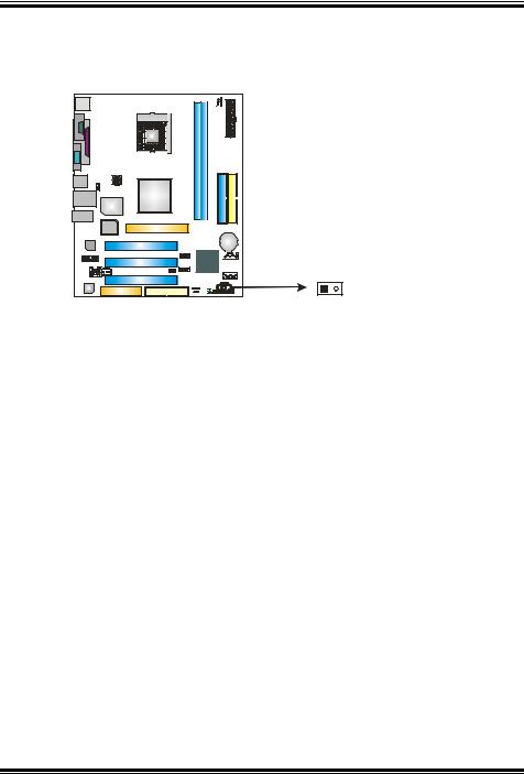
JCI1: Chassis Open Header
This connector allows system to monitor PC case open status. If the signal has been triggered, it will record to the CMOS and show the message on next boot-up.
PU |
|
|
|
Pin |
Assignment |
|
1 |
Case open signal |
|
2 |
Ground |
1 |
2 |
|
18
P4M80-M4
CHAPTER 4: USEFUL HELP
4.1 |
AWARD BIOS BEEP CODE |
|
|
|
|
Beep Sound |
Meaning |
|
One long beep followed by two short |
Video card not found or video card |
|
|
beeps |
memory bad |
|
|
High-low siren sound |
CPU overheated |
|
|
|
|
System will shut down automatically |
|
One Short beep when system boot-up |
No error found during POST |
|
|
Long beeps every other second |
No DRAM detected or install |
|
4.2EXTRA INFORMATION
A. BIOS Update
After you fail to update BIOS or BIOS is invaded by virus, the Boot-Block function will help to restore BIOS. If the following message is shown after boot-up the system, it means the BIOS contents are corrupted.
In this Case, please follow the procedure below to restore the BIOS:
1.Make a bootable floppy disk.
2.Download the Flash Utility “AWDFLASH.exe” from the Biostar website: www.biostar.com.tw
3.Confirm motherboard model and download the respectively BIOS from Biostar website.
4.Copy “AWDFLASH.exe” and respectively BIOS into floppy disk.
5.Insert the bootable disk into floppy drive and press Enter.
6.System will boo-up to DOS prompt.
7.Type “Awdflash xxxx.bf/sn/py/r” in DOS prompt.
8.System will update BIOS automatically and restart.
9.The BIOS has been recovered and will work properly.
19

P4M80-M4
B. CPU Overheated
If the system shutdown automatically after power on system for seconds, that means the CPU protection function has been activated.
When the CPU is over heated, the motherboard will shutdown automatically to avoid a damage of the CPU, and the system may not power on again.
In this case, please double check:
1.The CPU cooler surface is placed evenly with the CPU surface.
2.CPU fan is rotated normally.
3.CPU fan speed is fulfilling with the CPU speed.
After confirmed, please follow steps below to relief the CPU protection function.
1.Remove the power cord from power supply for seconds.
2.Wait for seconds.
3.Plug in the power cord and boot up the system.
Or you can:
1.Clear the CMOS data.
(See “Close CMOS Header: JCMOS1” section)
2.Wait for seconds.
3.Power on the system again.
20

P4M80-M4
4.3TROUBLESHOOTING
|
Probable |
|
Solution |
|
1. |
No power to the system at all |
1. |
Make sure power cable is |
|
|
Power light don’t illuminate, fan |
|
securely plugged in. |
|
|
inside power supply does not turn |
2. |
Replace cable. |
|
|
on. |
3. |
Contact technical support. |
|
2. |
Indicator light on keyboard does |
|||
|
|
|||
|
not turn on. |
|
|
|
System inoperative. Keyboard lights |
Using even pressure on both ends of |
|||
are on, power indicator lights are lit, |
the DIMM, press down firmly until the |
|||
and hard drive is spinning. |
module snaps into place. |
|||
System does not boot from hard disk |
1. |
Check cable running from disk to |
||
drive, can be booted from optical drive. |
|
disk controller board. Make sure |
||
|
|
|
both ends are securely plugged |
|
|
|
|
in; check the drive type in the |
|
|
|
|
standard CMOS setup. |
|
|
|
2. |
Backing up the hard drive is |
|
|
|
|
extremely important. All hard |
|
|
|
|
disks are capable of breaking |
|
|
|
|
down at any time. |
|
System only boots from optical drive. |
1. |
Back up data and applications |
||
Hard disk can be read and applications |
|
files. |
||
can be used but booting from hard disk |
2. |
Reformat the hard drive. |
||
is impossible. |
|
Re-install applications and data |
||
|
|
|
using backup disks. |
|
Screen message says “Invalid |
Review system’s equipment. Make sure |
|||
Configuration” or “CMOS Failure.” |
correct information is in setup. |
|||
Cannot boot system after installing |
1. |
Set master/slave jumpers |
||
second hard drive. |
|
correctly. |
||
|
|
2. |
Run SETUP program and select |
|
|
|
|
correct drive types. Call the drive |
|
|
|
|
manufacturers for compatibility |
|
|
|
|
with other drives. |
|
21
Loading...