


A780G M2+ SE/A780V M2+ SE/A740G M2+ SE
Setup Manual 
FCC Information and Copyright
This equipment has been tested and found to comply with the limits of a Class B digital device, pursuant to Part 15 of the FCC Rules. These limits are designed to provide reasonable protection against harmful interference in a residential installation. This equipment generates, uses, and can radiate radio frequency energy and, if not installed and used in accordance with the instructions, may cause harmful interference to radio communications. There is no guarantee that interference will not occur in a particular installation.
The vendor makes no representations or warranties with respect to the contents here and specially disclaims any implied warranties of merchantability or fitness for any purpose. Further the vendor reserves the right to revise this publication and to make changes to the contents here without obligation to notify any party beforehand.
Duplication of this publication, in part or in whole, is not allowed without first obtaining the vendor’s approval in writing.
The content of this user’s manual is subject to be changed without notice and we will not be responsible for any mistakes found in this user’s manual. All the brand and product names are trademarks of their respective companies.

|
Table of Contents |
|
Chapter 1: Introduction ............................................................ |
1 |
|
1.1 |
Before You Start ................................................................................ |
1 |
1.2 |
Package Checklist............................................................................. |
1 |
1.3 |
Motherboard Features...................................................................... |
2 |
1.4 |
Rear Panel Connectors ..................................................................... |
3 |
1.5 |
Motherboard Layout......................................................................... |
4 |
Chapter 2: Hardware Installation ............................................. |
5 |
|
2.1 |
Installing Central Processing Unit (CPU)....................................... |
5 |
2.2 |
FAN Headers...................................................................................... |
7 |
2.3 |
Installing System Memory................................................................ |
8 |
2.4 |
Connectors and Slots ....................................................................... |
10 |
Chapter 3: Headers & Jumpers Setup..................................... |
13 |
|
3.1 |
How to Setup Jumpers .................................................................... |
13 |
3.2 |
Detail Settings.................................................................................. |
13 |
Chapter 4: Hybrid CrossFireX Function (for A780G M2+ SE/ |
|
|
|
A780V M2+ SE) ..................................................... |
20 |
4.1 |
Hybrid CrossFireX Requirements.................................................. |
20 |
4.2 |
Hybrid CrossFireX Installation....................................................... |
20 |
Chapter 5: RAID Functions ..................................................... |
21 |
|
5.1 |
Operation System............................................................................ |
21 |
5.2 |
Raid Arrays ...................................................................................... |
21 |
5.3 |
How RAID Works............................................................................. |
21 |
Chapter 6: Useful Help ............................................................ |
24 |
|
6.1 |
Driver Installation Note.................................................................. |
24 |
6.2 |
Software............................................................................................ |
25 |
6.3 |
Extra Information............................................................................ |
29 |
6.4 |
AMI BIOS Beep Code....................................................................... |
31 |
6.5 |
Troubleshooting............................................................................... |
32 |
Appendix: SPEC In Other Language........................................ |
34 |
|
German.................................................................................................................. |
|
34 |
France .................................................................................................................... |
|
36 |
Italian..................................................................................................................... |
|
38 |
Spanish ................................................................................................................... |
|
40 |
Portuguese ............................................................................................................ |
42 |
|
Polish...................................................................................................................... |
|
44 |
Russian ................................................................................................................... |
|
46 |
Arabic..................................................................................................................... |
|
48 |
Japanese ................................................................................................................ |
|
50 |

 A780G M2+ SE/A780V M2+ SE/A740G M2+ SE
CHAPTER 1: INTRODUCTION
1.1BEFORE YOU START
Thank you for choosing our product. Before you start installing the motherboard, please make sure you follow the instructions below:
Prepare a dry and stable working environment with sufficient lighting.
Always disconnect the computer from power outlet before operation.
Before you take the motherboard out from anti-static bag, ground yourself properly by touching any safely grounded appliance, or use grounded wrist strap to remove the static charge.
Avoid touching the components on motherboard or the rear side of the board unless necessary. Hold the board on the edge, do not try to bend or flex the board.
Do not leave any unfastened small parts inside the case after installation. Loose parts will cause short circuits which may damage the equipment.
Keep the computer from dangerous area, such as heat source, humid air and water.
1.2PACKAGE CHECKLIST
HDD Cable X 1 Serial ATA Cable X 1
Rear I/O Panel for ATX Case X 1 Installation Guide X 1
Fully Setup Driver CD X 1 (full version manual files inside) FDD Cable X 1 (optional)
USB 2.0 Cable X1 (optional) S/PDIF out Cable X 1 (optional)
Serial ATA Power Cable X 1 (optional)
Note: The package contents may differ by area or your motherboard version.
1

Motherboard Manual 
1.3MOTHERBOARD FEATURES
|
A780G M2+ SE/A780V M2+ SE |
A740G M2+ SE |
|
|
Socket AM2+ / AM2 |
Socket AM2+ / AM2 |
|
|
AMD Athlon 64 / Athlon 64 FX / Athlon 64 x2 / |
AMD Athlon 64 / Athlon 64 FX / Athlon 64 x2 / |
|
|
Sempron / Phenom processors |
Sempron / Phenom processors |
|
CPU |
(95W CPU is recommended) |
(95W CPU is recommended) |
|
|
AMD 64 Architecture enables 32 and 64 bit |
AMD 64 Architecture enables 32 and 64 bit |
|
|
computing |
computing |
|
|
Supports Hyper Transport 3.0 and PowerNow |
Supports Hyper Transport 2.0 and PowerNow |
|
FSB |
Support HyperTransport 3.0 |
Support HyperTransport 2.0 |
|
Supports up to 5.2 GT/s Bandwidth |
Supports up to 2.0 GT/s Bandwidth |
||
|
|||
|
AMD 780G (A780G M2+ SE) |
AMD 740G |
|
Chipset |
AMD 780V (A780V M2+ SE) |
||
AMD SB700 |
|||
|
AMD SB700 |
||
|
|
||
|
ITE 8718F |
ITE 8718F |
|
|
Provides the most commonly used legacy Super |
Provides the most commonly used legacy Super |
|
|
I/O functionality |
I/O functionality |
|
Super I/O |
Low Pin Count Interface |
Low Pin Count Interface |
|
|
Environment Control initiatives |
Environment Control initiatives |
|
|
H/W Monitor |
H/W Monitor |
|
|
ITE's "Smart Guardian" function |
ITE's "Smart Guardian" function |
|
|
DDR2 DIMM Slots x 2 |
DDR2 DIMM Slots x 2 |
|
|
Max Memory Capacity 8GB |
Max Memory Capacity 8GB |
|
|
Each DIMM supports 256MB/512MB/ |
Each DIMM supports 256MB/512MB/ |
|
Main |
1GB/2GB/4GB DDR2 |
1GB/2GB/4GB DDR2 |
|
Dual Channel Mode DDR2 memory module |
Dual Channel Mode DDR2 memory module |
||
Memory |
|||
Supports DDR2 533 / 667 / 800 |
Supports DDR2 533 / 667 / 800 |
||
|
|||
|
Supports DDR2 1066 (for AM2+ CPU only) |
Supports DDR2 1066 (for AM2+ CPU only) |
|
|
Registered DIMM and ECC DIMM is not |
Registered DIMM and ECC DIMM is not |
|
|
supported |
supported |
|
|
ATI Radeon HD 3200 (A780G M2+ SE) |
|
|
|
ATI Radeon HD 3100 (A780V M2+ SE) |
ATI Radeon HD 2100 |
|
|
Max Shared Video Memory is 512MB |
||
Graphics |
Max Shared Video Memory is 512MB |
||
DX10/HDCP support |
|||
|
HDCP support |
||
|
Hybrid CrossFireX support |
||
|
|
||
|
UVD support (for A780G M2+ SE only) |
|
|
|
Integrated IDE Controller |
Integrated IDE Controller |
|
IDE |
Ultra DMA 33 / 66 / 100 / 133 Bus Master Mode |
Ultra DMA 33 / 66 / 100 / 133 Bus Master Mode |
|
|
supports PIO Mode 0~4, |
supports PIO Mode 0~4, |
|
|
Integrated Serial ATA Controller |
Integrated Serial ATA Controller |
|
SATA II |
Data transfer rates up to 3 Gb/s |
Data transfer rates up to 3 Gb/s |
|
|
SATA Version 2.0 specification compliant |
SATA Version 2.0 specification compliant |
|
|
Realtek RTL 8111C (A780G M2+ SE) |
|
|
|
Realtek RTL 8102EL (A780V M2+ SE) |
Realtek RTL 8102EL |
|
|
10 / 100 /1000 Mb/s auto negotiation (A780G |
||
LAN |
10 / 100 Mb/s auto negotiation |
||
M2+ SE) |
|||
|
Half / Full duplex capability |
||
|
10 /100 Mb/s auto negotiation (A780V M2+SE) |
||
|
Half / Full duplex capability |
|
2
 A780G M2+ SE/A780V M2+ SE/A740G M2+ SE
|
A780G M2+ SE/A780V M2+ SE |
A740G M2+ SE |
|
||
|
ALC662 |
|
ALC662 |
|
|
Sound |
5.1 channels audio out |
|
5.1 channels audio out |
|
|
|
High Definition Audio |
|
High Definition Audio |
|
|
|
PCI Express Gen2 x16 slot |
x1 |
PCI Express x16 slot |
x1 |
|
Slots |
PCI Express Gen2 x1 slot |
x1 |
PCI Express x1 slot |
x1 |
|
|
PCI slot |
x2 |
PCI slot |
x2 |
|
|
Floppy connector |
x1 |
Floppy connector |
x1 |
|
|
IDE Connector |
x1 |
IDE Connector |
x1 |
|
|
SATA Connector |
x6 |
SATA Connector |
x6 |
|
|
Front Panel Connector |
x1 |
Front Panel Connector |
x1 |
|
|
Front Audio Connector |
x1 |
Front Audio Connector |
x1 |
|
|
CD-in Connector |
x1 |
CD-in Connector |
x1 |
|
On Board |
S/PDIF out connector |
x1 |
S/PDIF out connector |
x1 |
|
CPU Fan header |
x1 |
CPU Fan header |
x1 |
||
Connector |
|||||
System Fan header |
x1 |
System Fan header |
x1 |
||
|
|||||
|
CMOS clear header |
x1 |
CMOS clear header |
x1 |
|
|
USB connector |
x3 |
USB connector |
x3 |
|
|
Power Connector (24pin) |
x1 |
Power Connector (24pin) |
x1 |
|
|
Power Connector (4pin) |
x1 |
Power Connector (4pin) |
x1 |
|
|
Printer Port Connector |
x1 |
Printer Port Connector |
x1 |
|
|
Serial port Connector |
x1 |
Serial port Connector |
x1 |
|
|
PS/2 Keyboard |
x1 |
PS/2 Keyboard |
x1 |
|
|
PS/2 Mouse |
x1 |
PS/2 Mouse |
x1 |
|
Back Panel |
DVI port |
x1 |
DVI port |
x1 |
|
I/O |
VGA port |
x1 |
VGA port |
x1 |
|
LAN port |
x1 |
LAN port |
x1 |
||
|
|||||
|
USB Port |
x4 |
USB Port |
x4 |
|
|
Audio Jack |
x3 |
Audio Jack |
x3 |
|
Board Size |
200 mm(W) x 244 mm(L) |
|
200 mm(W) x 244 mm(L) |
|
|
Special |
RAID 0 / 1 / 1+0 support |
|
RAID 0 / 1 / 1+0 support |
|
|
Features |
|
|
|||
|
|
|
|
||
|
Windows XP / VISTA |
|
Windows XP / VISTA |
|
|
OS Support |
Biostar Reserves the right to add or remove |
Biostar Reserves the right to add or remove |
|||
|
support for any OS With or without notice. |
support for any OS With or without notice. |
|||
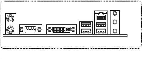
1.4REAR PANEL CONNECTORS
PS/2 |
|
|
LAN |
Mouse |
|
|
Line In/ |
|
|
|
Surround |
|
|
|
Line Out |
|
|
|
Mic In 1/ |
|
|
|
|
|
|
|
Bass/ Center |
PS/2 |
VGA |
DVI-D |
USBX2 USBX2 |
Keyboard |
|
|
|
3

Motherboard Manual 
1.5MOTHERBOARD LAYOUT
JKBMS1
JATXPWR2
JKBV1
VGA
DVI |
|
|
JUSB1 |
|
|
JUSBV1 |
|
|
JUSBLAN1 |
|
|
JAUDIO1 |
|
|
JAUDIOF1 |
|
|
JSPDIF_OUT1 |
|
|
JCDIN1 |
PEX1_1 |
|
LAN |
||
|
AM2+ Socket


AMD |
780G/ |
780V/ |
740G |
JCFAN1
JATXPWR1
DIMMA1 |
DIMMB1 |
BAT1 |
IDE1 |
|
SATA6
SATA5
SATA4
PEX16_1
BIOS
Super I/O
JCMOS1
|
PCI1 |
AMD |
|
|
|
|
SB700 |
SATA3 |
|
|
|
|
|
|
|
PCI2 |
|
SATA2 |
|
Codec |
JUSBV2 |
|
||
|
|
|||
JPRNT1 |
JCOM1 |
JSFAN1 |
SATA1 |
|
FDD1 |
|
JUSB4 JUSB3 JUSB2 |
JPANEL1 |
Note: ■ represents the 1st pin.
4
 A780G M2+ SE/A780V M2+ SE/A740G M2+ SE
CHAPTER 2: HARDWARE INSTALLATION
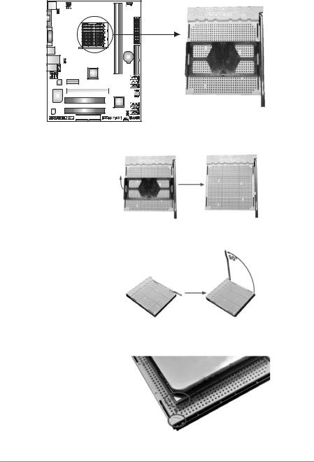
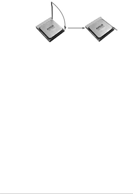
2.1INSTALLING CENTRAL PROCESSING UNIT (CPU)
Step 1: Remove the socket protection cap.
Step 2: Pull the lever toward direction A from the socket and then raise the lever up to a 90-degree angle.
Step 3: Look for the white triangle on socket, and the gold triangle on CPU should point towards this white triangle. The CPU will fit only in the correct orientation.
5
Motherboard Manual 
Step 4: Hold the CPU down firmly, and then close the lever toward direct B to complete the installation.
Step 5: Put the CPU Fan on the CPU and buckle it. Connect the CPU FAN power cable to the JCFAN1. This completes the installation.
Note: Please update the BIOS to the latest version while using AM2+ CPUs. Due to the latest CPU transition, you may encounter the situation that the new system failed to boot while using new AM2+ CPUs. In this case, please install one standard AM2 CPU to boot your system, and update the latest BIOS from our website for AM2+ CPUs support.
6
 A780G M2+ SE/A780V M2+ SE/A740G M2+ SE
2.2FAN HEADERS
These fan headers support cooling-fans built in the computer. The fan cable and connector may be different according to the fan manufacturer. Connect the fan cable to the connector while matching the black wire to pin#1.
JCFAN1: CPU Fan Header
4 |
1 |
JSFAN1: System Fan Header
Pin Assignment
1Ground
2+12V
3FAN RPM rate sense
4Smart Fan Control (By Fan)
1 |
3 |
Note: |
|
Pin Assignment
1Ground
2+12V
3FAN RPM rate sense
The JCFAN1 supports 4-pin head connector. The JSFAN1 supports 3-pin head connector. When connecting with wires onto connectors, please note that the red wire is the positive and should be connected to pin#2, and the black wire is Ground and should be connected to GND.
7
Motherboard Manual 
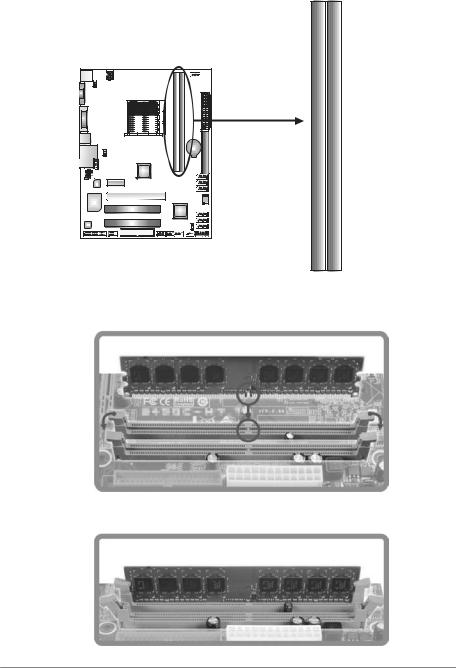
2.3INSTALLING SYSTEM MEMORY
A. Memory Modules
DIMMB1
DIMMA1
1.Unlock a DIMM slot by pressing the retaining clips outward. Align a DIMM on the slot such that the notch on the DIMM matches the break on the Slot.
2.Insert the DIMM vertically and firmly into the slot until the retaining chip snap back in place and the DIMM is properly seated.
8
 A780G M2+ SE/A780V M2+ SE/A740G M2+ SE
B. Memory Capacity
DIMM Socket |
DDR2 Module |
Total Memory |
|
Location |
Size |
||
|
|||
DIMMA1 |
256MB/512MB/1GB/2GB/4GB |
Max is 8GB. |
|
DIMMB1 |
256MB/512MB/1GB/2GB/4GB |
||
|
|||
|
|
|
C. Dual Channel Memory installation
To trigger the Dual Channel function of the motherboard, the memory module must meet the following requirements:
Install memory module of the same density in pairs, shown in the following table.
Dual Channel Status |
DIMMA1 |
DIMMB1 |
Disabled |
X |
O |
Disabled |
O |
X |
Enabled |
O |
O |
(O means memory installed, X means memory not installed.)
The DRAM bus width of the memory module must be the same (x8 or x16)
9
Motherboard Manual 
2.4CONNECTORS AND SLOTS
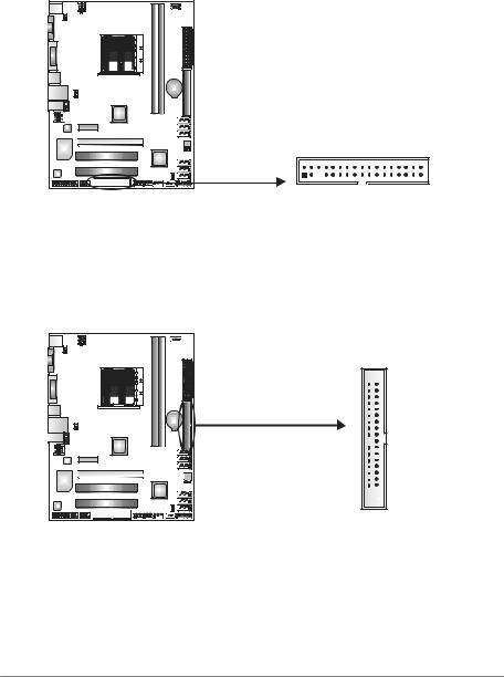
FDD1: Floppy Disk Connector
The motherboard provides a standard floppy disk connector that supports 360K, 720K, 1.2M, 1.44M and 2.88M floppy disk types. This connector supports the provided floppy drive ribbon cable.
2 34
1 33
IDE1: IDE/ATAPI Connector
The motherboard has a 32-bit Enhanced PCI IDE Controller that provides PIO Mode 0~4, Bus Master, and Ultra DMA 33/66/100/133 functionality.
The IDE connector can connect a master and a slave drive, so you can connect up to two drives.
40 
 39
39
2 
 1
1
10
 A780G M2+ SE/A780V M2+ SE/A740G M2+ SE
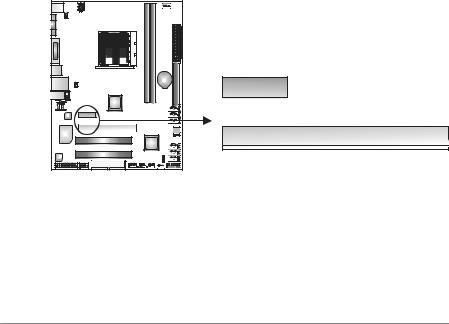
PEX16_1: PCI-Express Gen2 x16 Slot (for A780G M2+ SE/A780V M2+ SE)
-PCI-Express 2.0 compliant.
-Maximum theoretical realized bandwidth of 8GB/s simultaneously per direction, for an aggregate of 16GB/s totally.
PEX1_1: PCI-Express Gen2 x1 Slot (for A780G M2+ SE/A780V M2+
SE)
-PCI-Express 2.0 compliant.
-Data transfer bandwidth up to 500MB/s per direction; 1GB/s in total.
-PCI-Express supports a raw bit-rate of 5.0Gb/s on the data pins.
-2X bandwidth over the PCI-Express 1.1 architecture.
PEX16_1: PCI-Express x16 Slot (for A740G M2+ SE)
-PCI-Express 1.1 compliant.
-Maximum theoretical realized bandwidth of 4GB/s simultaneously per direction, for an aggregate of 8GB/s totally.
PEX1_1: PCI-Express x1 Slot (for A740G M2+ SE)
-PCI-Express 1.1 compliant.
-Data transfer bandwidth up to 250MB/s per direction; 500MB/s in total.
-PCI-Express supports a raw bit-rate of 2.5GB/s on the data pins.
-2X bandwidth over the traditional PCI architecture.
PEX1_1
PEX16_1
11
Motherboard Manual 
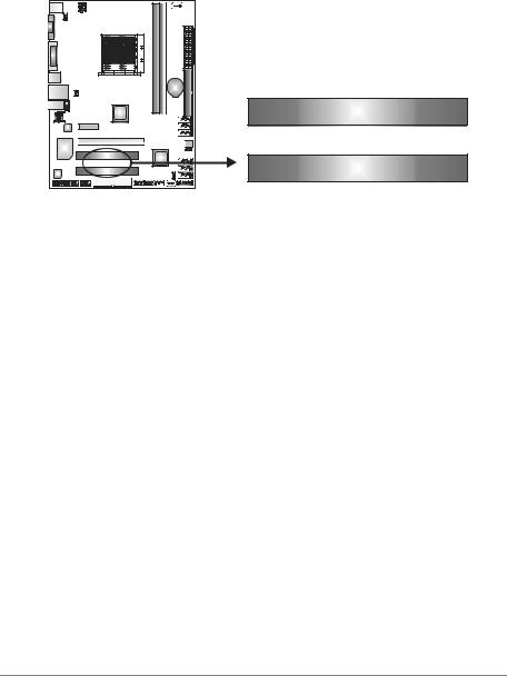
PCI1~PCI2: Peripheral Component Interconnect Slots
This motherboard is equipped with 2 standard PCI slots. PCI stands for Peripheral Component Interconnect, and it is a bus standard for expansion cards. This PCI slot is designated as 32 bits.
PCI1
PCI2
12
 A780G M2+ SE/A780V M2+ SE/A740G M2+ SE
CHAPTER 3: HEADERS & JUMPERS SETUP
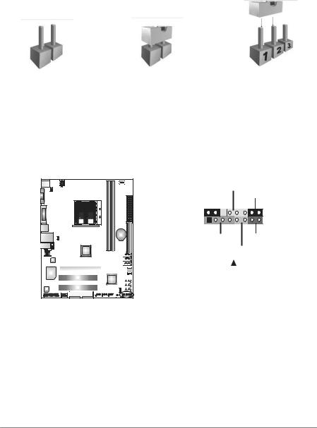
3.1HOW TO SETUP JUMPERS
The illustration shows how to set up jumpers. When the jumper cap is placed on pins, the jumper is “close”, if not, that means the jumper is “open”.
Pin opened |
Pin closed |
Pin1-2 closed |
3.2DETAIL SETTINGS
JPANEL1: Front Panel Header
This 16-pin connector includes Power-on, Reset, HDD LED, Power LED, and speaker connection. It allows user to connect the PC case’s front panel switch functions.
PWR_LED
On/Off
9 |
+ + - |
16 |
|
||
1 |
+ - |
8 |
|
|
|
SPK |
RST |
|
|
HLED |
|
|
|
|
|
|
|
|
|
|
|
|
|
|
|
|
|
|
|
|
|
|
|
|
|
|
|
|
|
|
|
|
|
|
|
|
|
|
|
|
|
|
|
|
|
|
|
|
|
|
|
|
|
|
|
|
|
|
|
|
|
|
|
|
|
|
|
|
|
|
|
|
|
|
|
|
|
|
|
|
|
|
|
|
|
|
|
|
|
|
|
|
|
|
|
|
|
|
|
|
|
|
|
|
|
|
|
|
|
|
|
|
|
|
|
|
|
|
|
|
|
|
|
|
|
|
|
|
|
|
|
|
|
|
|
|
|
|
|
|
|
|
|
|
|
|
|
|
|
|
|
|
|
|
|
|
|
|
|
|
|
|
|
|
|
|
|
|
|
|
|
|
|
|
|
|
|
|
|
|
|
|
|
|
|
|
|
|
|
|
|
|
|
|
|
|
|
|
|
|
|
|
|
|
|
|
|
|
|
|
|
|
|
|
|
|
|
|
|
|
|
|
|
|
|
|
|
|
|
|
|
|
|
|
|
|
|
|
|
|
|
|
|
|
|
|
|
|
|
|
|
|
|
|
Pin |
|
|
|
Assignment |
|
|
|
|
Function |
Pin |
Assignment |
Function |
||||||||||
1 |
|
+5V |
|
|
|
|
|
9 |
N/A |
N/A |
||||||||||||
2 |
|
N/A |
|
|
|
|
Speaker |
10 |
N/A |
|||||||||||||
|
|
|
|
|
|
|||||||||||||||||
3 |
|
N/A |
|
|
|
|
Connector |
11 |
N/A |
N/A |
||||||||||||
4 |
|
Speaker |
|
|
|
|
|
12 |
Power LED (+) |
Power LED |
||||||||||||
5 |
|
HDD LED (+) |
|
|
|
|
Hard drive |
13 |
Power LED (+) |
|||||||||||||
6 |
|
HDD LED (-) |
|
|
|
|
LED |
14 |
Power LED (-) |
|
||||||||||||
7 |
|
Ground |
|
|
|
|
Reset button |
15 |
Power button |
Power-on button |
||||||||||||
8 |
|
Reset control |
|
|
|
|
16 |
Ground |
||||||||||||||
|
|
|
|
|
|
|
||||||||||||||||
13
Motherboard Manual 
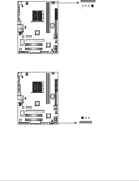
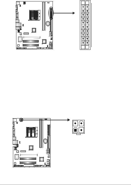
JATXPWR1: ATX Power Source Connector
This connector allows user to connect 24-pin power connector on the ATX power supply.
Pin |
Assignment |
13+3.3V
14-12V
15Ground
16PS_ON
17Ground
18Ground
19Ground
20NC
21+5V
22+5V
23+5V
24Ground
12 

 24
24
1 

 13
13
Pin Assignment
1+3.3V
2+3.3V
3Ground
4+5V
5Ground
6+5V
7Ground
8PW_OK
9Standby Voltage+5V
10+12V
11+12V
12+3.3V
JATXPWR2: ATX Power Source Connector
By connecting this connector, it will provide +12V to CPU power circuit.
Note: |
4 |
3 |
|
|
|
|
Pin |
Assignment |
1 |
2 |
1 |
+12V |
|
|
2 |
+12V |
|
|
3 |
Ground |
|
|
4 |
Ground |
Before power on the system, please make sure that both JATXPWR1 and JATXPWR2 connectors have been plugged-in.
14
 Loading...