


865GV Micro 478
FCC Information and Copyright
This equipment has been tested and found to comply with the limits of a Class B digital device, pursuant to Part 15 of the FCC Rules. These limits are designed to provide reasonable protection against harmful interference in a residential installation. This equipment generates, uses and can radiate radio frequency energy and, if not installed and used in accordance with the instructions, may cause harmful interference to radio communications. There is no guarantee that interference will not occur in a particular installation.
The vendor makes no representations or warranties with respect to the contents here and specially disclaims any implied warranties of merchantability or fitness for any purpose. Further the vendor reserves the right to revise this publication and to make changes to the contents here without obligation to notify any party beforehand.
Duplication of this publication, in part or in whole, is not allowed without first obtaining the vendor’s approval in writing.
The content of this user’s manual is subject to be changed without notice and we will not be responsible for any mistakes found in this user’s manual. All the brand and product names are trademarks of their respective companies.
i

Table of Contents
Chapter 1: Introduction .......................................................... |
1 |
|
1.1 |
Motherboard Features .......................................................... |
1 |
1.2 |
Package Checklist ................................................................ |
4 |
1.3 |
Layout and Components....................................................... |
5 |
Chapter 2: Hardware Installation ........................................... |
6 |
|
2.1 |
Installing Central Processing Unit (CPU).............................. |
6 |
2.2 |
FAN Headers ........................................................................ |
7 |
2.3 |
Installing System Memory..................................................... |
8 |
2.4 |
Connectors and Slots............................................................ |
9 |
Chapter 3: Headers & Jumpers Setup................................. |
12 |
|
3.1 |
How to Setup Jumpers ....................................................... |
12 |
3.2 |
Detail Settings..................................................................... |
12 |
Chapter 4: Useful Help.......................................................... |
19 |
|
4.1 |
Driver Installation Note........................................................ |
19 |
4.2 |
Award BIOS Beep Code ..................................................... |
20 |
4.3 |
Extra Information................................................................. |
21 |
4.4 |
Troubleshooting .................................................................. |
23 |
Chapter 5: WarpSpeeder™................................................... |
24 |
|
5.1 |
Introduction ......................................................................... |
24 |
5.2 |
System Requirement .......................................................... |
24 |
5.3 |
Installation........................................................................... |
25 |
5.4 |
[WarpSpeeder™] includes 1 tray icon and 5 panels........... |
26 |
ii

865GV Micro 478
CHAPTER 1: INTRODUCTION
1.1MOTHERBOARD FEATURES
CPU
Support Socket 478
Support Northwood and Prescott CPU up to 3.4GHz. (Does not support Willamette CPU.)
Front Side Bus at 400/533/800MHz. Supports Intel Hyper-Threading Technology.
WARNING!
Warranty will be void if the pin protection cap is not in place to protect the CPU socket pin when sending this mainboard for service.
Chipset
North Bridge: Intel 865GV.
South Bridge: Intel ICH5.
Dimensions
Micro ATX Form Factor: 21.5cm (W) x 23.5cm (L)
Operating System Supporting
Supports Windows 2000, and Windows XP.
System Memory
Supports dual channel DDR up to 4 banks.
Supports DDR 400 (200MHz) for a theoretical maximum bandwidth of 6.4GB/s.
Available bandwidth up to 3.2GB/s (DDR400) for single channel mode and 6.4GB/s (DDR400) for dual channel mode
Supports 256MB, 512MB, or 1GB DDR.
Supports non-ECC DIMMs.
Registered memory are not supported. Maximum DRAM capacity up to 2 GB.
DIMM Socket |
DDR Module |
Total Memory Size |
|
Location |
|||
|
|
||
DDRA1 |
256MB/512MB/1GB *1 |
Max is 2GB. |
|
DDRB1 |
256MB/512MB/1GB *1 |
||
|
1

865GV Micro 478
Super I/O
Chip: ITE IT8712F.
Provides the most commonly used legacy Super I/O functionality.
Environment Control initiatives,
H/W Monitor
ITE's "Smart Guardian" function
On Board IDE
One on-board connector supports 4 devices.
Supports PIO Mode 0~4.
Supports Ultra DMA 33/66/100 Bus Master Mode.
10/100 LAN
Chip: RTL8100C
Supports 10 Mb/s and 100 Mb/s auto-negotiation.
Half/Full duplex capability.
Supports ACPI power management.
Serial ATA
Controller integrated in ICH5.
Compliant with SATA Version 1.0 Specification.
Data transfer rate up to 150MB/s. Supports 2 Serial ATA (SATA) devices.
-Intel Advanced Host Controller (AHCI).
Onboard AC’97 Sound Codec
Chip: ALC655 / ALC658
Supports 6 channels.
Supports S/PDIF out function.
Compliant with AC’97 Version 2.3 specification.
Expansion Slots
Three PCI slots.
One XGP Slot
2
865GV Micro 478
Internal On-board I/O Connectors and Headers
2 IDE connector supports 4 hard disk devices.
1 front panel header supports front panel facilities.
1 CD-in connector supports 1 CD-ROM audio-in device.
1 front audio header supports front panel audio-out function.
1 S/PDIF-out connector supports digital audio-out function.
1 S/PDIF-in connector supports digital audio-in function. (optional)
1 chassis open header supports PC case-opened warning function.
1 Floppy port supports 2 FDD with 360K, 720K, 1.2M, 1.44M and 2.88Mbytes.
2 USB headers support 4 USB 2.0 ports.
2 Serial ATA connectors support 2 SATA devices.
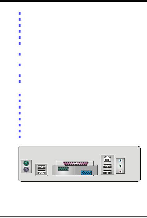
Back Panel I/O Connectors
1 Serial port.
1 Printer port.
1 VGA Port
1 PS/2 Mouse port.
1 PS/2 Keyboard port.
1 RJ-45 LAN jack.
4 USB 2.0 ports.
1 vertical audio port including 1 line-in connector, 1 line-out connector, and 1 MIC-in connector
PS/2
Mouse
PS/2 |
|
Keyboard |
USB x2 |
|
Parallel |
COM1 |
VGA1 |
|
|
JCOM1 |
JVGA1 |
LAN |
USB x2
Line In/
Surround
Line Out
Mic In 1/
Base/Center
3

865GV Micro 478
1.2PACKAGE CHECKLIST
FDD Cable X 1
HDD Cable X 1 User’s Manual X 1
Serial ATA Cable X 1 (optional) Fully Setup Driver CD X 1
Rear I/O Panel for ATX Case X 1 USB 2.0 Cable X1 (optional) S/PDIF Cable X 1 (optional)
Serial ATA Power Switch Cable X 1 (optional)
4

865GV Micro 478
1.3LAYOUT AND COMPONENTS
JKBMS1 |
JCFAN1 |
|
|
JKB USBV1 |
|
|
|
JATXPWR1 |
|
|
|
|
|
PU |
|
||
|
|
|
|
|
|
|
|
JUSB1 |
|
|
Socket 478 |
|
|
|
|
O |
|
|
|
CPU1 |
|
FDD1 |
|
JCOM1 |
|
|
|
|
|
|
|
M |
|
|
|
|
|
|
|
1 |
|
|
|
|
|
|
|
JPRNT1 |
|
|
|
|
|
DDRA1 |
|
JVGA1 |
|
JATXPWR2 |
|
|
|
|
|
|
|
|
|
|
|
|
|
|
|
JUSBV2 |
|
Intel |
|
IDE2 |
IDE1 |
|
|
|
|
|
|||
|
|
|
|
865GV |
|
||
JUSBLAN1 |
|
|
|
|
|
|
|
|
|
|
|
|
|
|
|
JAUDIO1 |
|
|
|
|
|
|
|
JAUDIO2 |
PCI |
XGP1 |
|
|
|
||
LAN |
|
|
|
||||
|
|
|
|
|
|
|
|
|
|
|
|
|
|
BAT1 |
|
Codec |
(Optional) |
PCI1 |
|
|
|
|
|
|
|
|
|
SATA2 |
|
||
|
|
JSPDIF_IN1 |
|
|
|
|
|
|
|
|
JSPDIF_OUT1 |
JUSB2 |
JUSB3 |
ICH5 |
|
|
|
JCDIN1 |
|
SATA1 |
|
||
|
|
|
|
|
|
||
PCI2
JUSBV3_4
JCI1
JSFAN1 JCMOS1
PCI3 |
BIOS |
|
JPANEL1 |
IR (optional) |
Note: ■ represents the 1st pin.
5

865GV Micro 478
CHAPTER 2: HARDWARE INSTALLATION
2.1INSTALLING CENTRAL PROCESSING UNIT (CPU)
Step 1: Pull the lever sideways away from the socket and then raise the lever up to a 90-degree angle.
Step 2: Look for the white dot/cut edge. The white dot/cut edge should point wards the lever pivot. The CPU will fit only in the correct orientation.
Step 3: Hold the CPU down firmly, and then close the lever to complete the installation.
Step 4: Put the CPU Fan on the CPU and buckle it. Connect the CPU FAN power cable to the JCFAN1. This completes the installation.
6

865GV Micro 478
2.2FAN HEADERS
These fan headers support cooling-fans built in the computer. The fan cable and connector may be different according to the fan manufacturer. Connect the fan cable to the connector while matching the black wire to pin#1.
JCFAN1: CPU Fan Header
JCFAN1 |
Pin |
Assignment |
||
1 |
3 |
1 |
Ground |
|
2 |
Power |
|||
|
|
|||
|
|
3 |
FAN RPM rate |
|
|
|
|
sense |
|
JSFAN1: System Fan Header
|
|
|
|
|
|
|
|
|
|
|
|
|
|
|
|
|
Pin |
Assignment |
|
|
|
|
|
|
|
|
|
|
|
|
|
|
|
|
|
||
|
|
|
|
|
|
|
|
|
|
|
|
|
|
|
|
|
||
|
|
|
|
|
|
|
|
|
|
|
|
|
|
|
|
|
||
|
|
|
|
|
|
|
|
|
|
|
|
|
|
|
|
|
||
|
|
|
|
|
|
|
|
|
|
|
|
|
|
|
|
|
||
|
|
|
|
|
|
|
|
|
|
|
|
|
|
|
|
|
||
|
|
|
|
|
|
|
|
|
|
|
|
|
|
|
|
|
||
|
|
|
|
|
|
|
|
|
|
|
|
|
|
|
|
|
1 |
Ground |
|
|
|
|
|
|
|
|
|
|
|
|
|
|
|
2 |
Power |
||
|
|
|
|
|
|
|
|
|
|
|
|
|
|
|
|
|
||
|
|
|
|
|
|
|
|
|
|
|
|
|
|
|
3 |
FAN RPM rate |
||
|
|
|
|
|
|
|
|
|
|
|
|
|
|
|
|
|
|
sense |
|
|
|
|
|
|
|
|
|
|
|
|
|
|
|
|
|
|
|
|
|
|
|
|
|
|
|
|
|
|
|
|
|
|
|
|
|
|
|
|
|
|
|
|
|
|
|
|
|
|
|
|
|
|
|
|
|
JSFAN1
1 3
7
865GV Micro 478
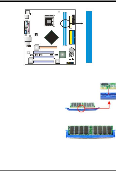
2.3INSTALLING SYSTEM MEMORY
DDRB1
DDRA1
1.Unlock a DIMM slot by pressing the retaining clips outward. Align a DIMM on the slot such that the notch on the DIMM matches the break on the Slot.
2.Insert the DIMM vertically and firmly into the slot until the retaining chip snap back in place and the DIMM is properly seated.
8
865GV Micro 478
2.4CONNECTORS AND SLOTS
FDD1: Floppy Disk Connector
The motherboard provides a standard floppy disk connector that supports 360K, 720K, 1.2M, 1.44M and 2.88M floppy disk types. This connector supports the provided floppy drive ribbon cables.
34 |
33 |
2 |
1 |
IDE1: Hard Disk Connector
The motherboard has a 32-bit Enhanced PCI IDE Controller that provides PIO Mode 0~4, Bus Master, and Ultra DMA 33/66/100 functionality.
The IDE connectors can connect a master and a slave drive, so you can connect up to two hard disk drives. The first hard drive should always be connected to IDE1.
IDE2 IDE1
40 |
39 |
2 |
1 |
9
865GV Micro 478
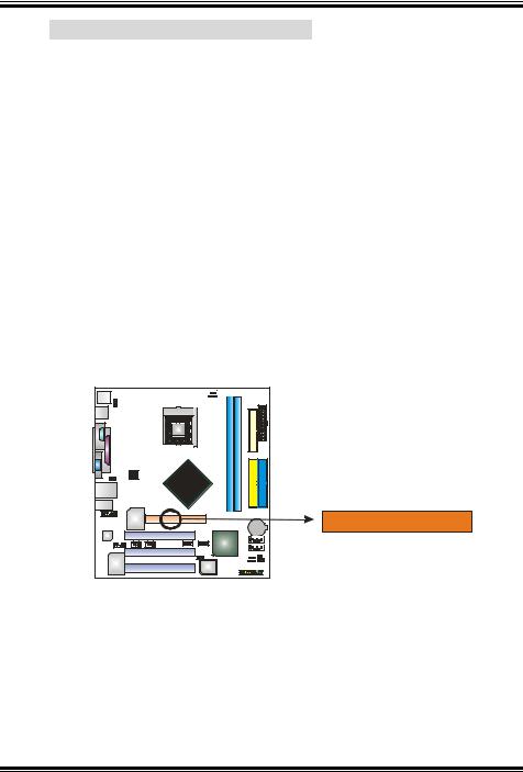
XGP1: Xtreme Graphics Port Slot
This XGP (Extreme Graphics Port) slot is a special design that only supports compatible AGP VGA cards.
To install the system with an add-on AGP VGA card, please make sure to install the driver of add-on AGP VGA card before onboard VGA driver installation. If the onboard VGA driver has already been installed before you install the add-on AGP VGA card, the system will automatically set the onboard VGA as the primary graphics adapter.
For the onboard VGA driver can’t be removed completely, and to solve this problem, please follow the steps below,
1.Disable onboard VGA utility under the operating system, and reboot PC. After PC restarts, the system will automatically set the AGP VGA card as the graphics adapter.
2.Or, re-install your operating system to ensure the AGP VGA card function can be used.
Note:
Please go to “http://www.biostar.com.tw” for more detailed information about XGP compatible AGP cards.
10
865GV Micro 478
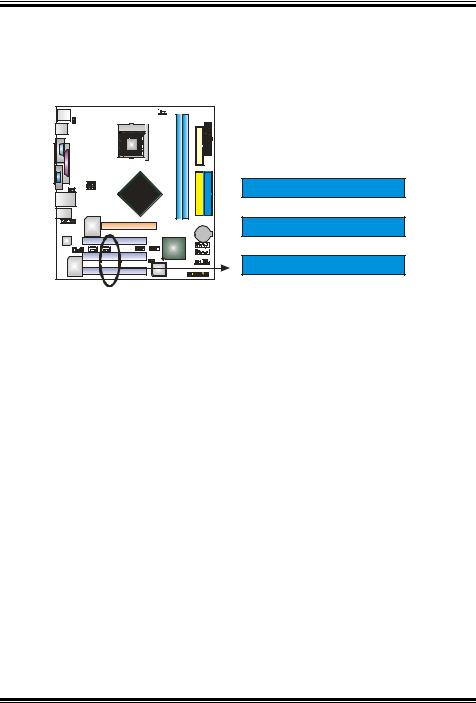
PCI1~PCI2: Peripheral Component Interconnect Slots
This motherboard is equipped with 2 standard PCI slots. PCI stands for Peripheral Component Interconnect, and it is a bus standard for expansion cards. This PCI slot is designated as 32 bits.
PCI1
PCI2
PCI3
11

865GV Micro 478
CHAPTER 3: HEADERS & JUMPERS SETUP
3.1HOW TO SETUP JUMPERS
The illustration shows how to set up jumpers. When the jumper cap is placed on pins, the jumper is “close”, if not, that means the jumper is “open”.
Pin opened |
Pin closed |
Pin1-2 closed |
3.2DETAIL SETTINGS
JATXPWR1: ATX Power Connector
This connector allows user to connect 24-pin power connector on the ATX power supply.
|
|
Pin |
Assignment |
|
|
|
1 |
+3.3V |
|
|
|
2 |
+3.3V |
|
|
|
3 |
Ground |
|
11 |
20 |
4 |
+5V |
|
5 |
Ground |
|||
|
|
6 |
+5V |
|
|
|
7 |
Ground |
|
|
|
8 |
PW_OK |
|
|
|
9 |
Standby |
|
|
|
|
Voltage +5V |
|
|
|
10 |
+12V |
|
|
|
11 |
+3.3V |
|
|
|
12 |
-12V |
|
|
|
13 |
Ground |
|
1 |
10 |
14 |
PS_ON |
|
15 |
Ground |
|||
|
|
|||
|
|
16 |
Ground |
|
|
|
17 |
Ground |
|
|
|
18 |
-5V |
|
|
|
19 |
+5V |
|
|
|
20 |
+5V |
12

865GV Micro 478
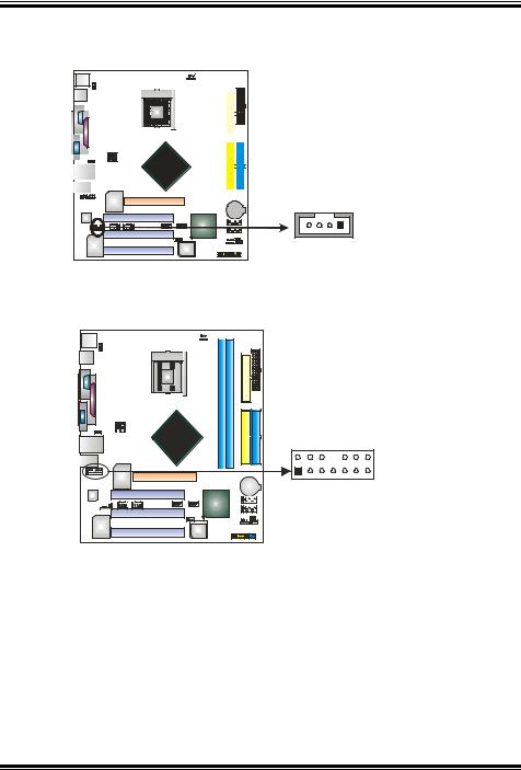
JATXPWR2: ATX Power Connector
By connecting this connector, it will provide +12V to CPU power circuit.
1 |
3 |
2 |
4 |
Pin Assignment
1+12V
2+12V
3Ground
4Ground
JSPDIF_OUT1: Digital Audio-out Connector
This connector allows user to connect the PCI bracket SPDIF output header.
|
|
|
|
|
|
|
|
|
|
|
|
|
|
|
|
|
Pin |
Assignment |
|
|
|
|
|
|
|
|
|
|
|
|
|
|
|
|
|
||
|
|
|
|
|
|
|
|
|
|
|
|
|
|
|
|
|
||
|
|
|
|
|
|
|
|
|
|
|
|
|
|
|
|
|
||
|
|
|
|
|
|
|
|
|
|
|
|
|
|
|
|
|
||
|
|
|
|
|
|
|
|
|
|
|
|
|
|
|
|
|
||
|
|
|
|
|
|
|
|
|
|
|
|
|
|
|
|
|
||
|
|
|
|
|
|
|
|
|
|
|
|
|
|
|
|
|
||
|
|
|
|
|
|
|
|
|
|
|
|
|
|
|
|
|
||
|
|
|
|
|
|
|
|
|
|
|
|
|
|
|
1 |
+5V |
||
|
|
|
|
|
|
|
|
|
|
|
|
|
|
|
|
|
||
|
|
|
|
|
|
|
|
|
|
|
|
|
|
|
2 |
SPDIF_OUT |
||
|
|
|
|
|
|
|
|
|
|
|
|
|
|
|
|
|
||
|
|
|
|
|
|
|
|
|
|
|
|
|
|
|
3 |
Ground |
||
|
|
|
|
|
|
|
|
|
|
|
|
|
|
|
|
|
||
|
|
|
|
|
|
|
|
|
|
|
|
|
|
|
|
|
|
|
3 1
JSPDIF_IN1 (optional): Digital Audio-in Connector
This connector allows user to connect the PCI bracket SPDIF input header.
|
|
|
|
|
|
|
|
|
|
|
|
|
|
|
|
|
|
|
|
|
|
|
|
|
Pin |
Assignment |
|
|
|
|
|
|
|
|
|
|
|
|
|
|
|
|
|
|
|
|
|
|
|
|
|
||
|
|
|
|
|
|
|
|
|
|
|
|
|
|
|
|
|
|
|
|
|
|
|
|
|
||
|
|
|
|
|
|
|
|
|
|
|
|
|
|
|
|
|
|
|
|
|
|
|
|
|
||
|
|
|
|
|
|
|
|
|
|
|
|
|
|
|
|
|
|
|
|
|
|
|
|
|
||
|
|
|
|
|
|
|
|
|
|
|
|
|
|
|
|
|
|
|
|
|
|
|
|
|
1 |
+5V |
|
|
|
|
|
|
|
|
|
|
|
|
|
|
|
|
|
|
|
|
|
|
|
|
|
||
|
|
|
|
|
|
|
|
|
|
|
|
|
|
|
|
|
|
|
|
|
|
|
|
|
2 |
SPDIF_IN |
|
|
|
|
|
|
|
|
|
|
|
|
|
|
|
|
|
|
|
|
|
|
|
|
|
||
|
|
|
|
|
|
|
|
|
|
|
|
|
|
|
|
|
|
|
|
|
|
|
|
|
||
|
|
|
|
|
|
|
|
|
|
|
|
|
|
|
|
|
|
|
|
3 |
1 |
|
3 |
Ground |
||
|
|
|
|
|
|
|
|
|
|
|
|
|
|
|
|
|
|
|
|
|
||||||
|
|
|
|
|
|
|
|
|
|
|
|
|
|
|
|
|
|
|
|
|
|
|
|
|
|
|
|
|
|
|
|
|
|
|
|
|
|
|
|
|
|
|
|
|
|
|
|
|
|
|
|
|
|
|
|
|
|
|
|
|
|
|
|
|
|
|
|
|
|
|
|
|
|
|
|
|
|
|
|
|
|
|
|
|
|
|
|
|
|
|
|
|
|
|
|
|
|
|
|
|
|
|
|
|
|
|
|
|
|
|
|
|
|
|
|
|
|
|
|
|
|
|
|
|
|
|
|
|
|
|
|
|
|
|
|
|
|
|
|
|
|
|
|
|
|
|
|
|
|
|
|
|
|
|
|
|
|
|
|
|
|
|
|
|
|
|
|
|
|
|
|
|
|
|
|
|
|
|
|
|
|
|
|
|
|
|
|
|
|
|
|
|
|
|
|
|
|
|
|
|
|
|
|
|
|
|
|
|
|
|
|
|
|
|
|
|
|
|
|
|
|
|
|
|
|
|
|
|
|
|
|
|
|
|
|
|
|
|
|
|
|
|
|
|
|
|
|
|
|
|
|
|
|
|
|
|
|
|
|
|
|
|
|
|
|
|
|
|
|
|
|
|
|
|
|
|
|
|
|
|
|
|
|
|
|
|
|
|
|
|
|
|
|
|
|
|
13
865GV Micro 478
JCDIN1: CD-ROM Audio-in Connector
This connector allows user to connect the audio source from the variety devices, like CD-ROM, DVD-ROM, PCI sound card, PCI TV turner card etc..
|
|
|
|
|
|
|
|
|
|
|
|
|
|
|
|
|
|
Pin |
Assignment |
|
|
|
|
|
|
|
|
|
|
|
|
|
|
|
|
|
|
||
|
|
|
|
|
|
|
|
|
|
|
|
|
|
|
|
|
|
||
|
|
|
|
|
|
|
|
|
|
|
|
|
|
|
|
|
|
||
|
|
|
|
|
|
|
|
|
|
|
|
|
|
|
|
|
|
||
|
|
|
|
|
|
|
|
|
|
|
|
|
|
|
|
|
|
1 |
Left channel input |
|
|
|
|
|
|
|
|
|
|
|
|
|
|
|
|
2 |
Ground |
||
|
|
|
|
|
|
|
|
|
|
|
|
|
|
|
|
|
|
||
|
|
|
|
|
|
|
|
|
|
|
|
|
|
|
|
3 |
Ground |
||
|
|
|
|
|
|
|
|
|
|
|
|
|
|
|
|
|
|||
|
|
|
|
|
|
|
|
|
|
|
|
|
|
|
|
|
|
||
|
|
|
|
|
|
|
|
|
|
|
|
|
|
|
|
4 |
Right channel input |
||
|
|
|
|
|
|
|
|
|
|
|
|
|
|
|
|
|
|
||
|
|
|
|
|
|
|
|
|
|
|
|
|
|
|
|
|
|
|
|
|
|
|
|
|
|
|
|
|
|
|
|
|
|
|
|
|
|
|
|
4 1
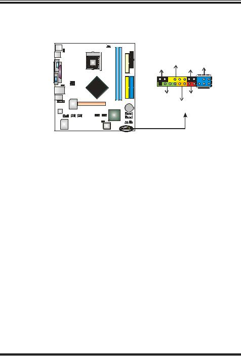
JAUDIO1: Front Panel Audio Header
This header allows user to connect the front audio output cable with the PC front panel. It will disable the output on back panel audio connectors.
|
|
Pin |
Assignment |
|
|
|
1 |
Mic (L) |
|
|
|
2 |
Ground |
|
|
|
3 |
Mic (R) |
|
|
|
4 |
PRESENCE |
|
|
|
5 |
Headphone (R) |
|
|
|
6 |
Jack 1 SENSE |
|
|
|
7 |
Jack Detection |
|
2 |
14 |
8 |
Connector Key |
|
9 |
Headphone (L) |
|||
|
|
|||
|
|
10 |
Jack 2 SENSE |
|
1 |
13 |
11 |
Right line-in |
|
12 |
Right line-in |
|||
|
|
|||
|
|
13 |
Left line-in |
|
|
|
14 |
Left line-in |
14
865GV Micro 478
JPANEL1: Front Panel Header
This 24-pin connector includes Power-on, Reset, HDD LED, Power LED, Sleep button, speaker and IrDA Connection. It allows user to connect the PC case’s front panel switch functions.
|
PWR_LED |
IR (optional) |
|
|
SLP |
On/Off |
|
12 |
+ + - |
22 |
|
|
|
||
1 |
+ |
- |
11 |
|
|
||
|
SPK |
RST |
|
|
HLED |
|
|
|
|
|
|
|
|
|
|
|
|
|
|
|
|
|
|
|
|
|
|
|
|
|
|
|
|
|
|
|
|
|
|
|
|
|
|
|
|
|
|
|
|
|
|
|
|
|
|
|
|
|
|
|
|
|
|
|
|
|
|
|
|
|
|
|
|
|
|
|
|
|
|
|
|
|
|
|
|
|
|
|
|
|
|
|
|
|
|
|
|
|
|
|
|
|
|
|
|
|
|
|
|
|
|
|
|
|
|
|
|
|
|
|
|
|
|
|
|
|
|
|
|
|
|
|
|
|
|
|
|
|
|
|
|
|
|
|
|
|
|
Pin |
Assignment |
|
|
|
|
Function |
|
|
Pin |
Assignment |
Function |
||||||||||||||||
1 |
+5V |
|
|
|
|
|
|
|
|
|
|
12 |
Sleep control |
Sleep button |
|||||||||||||
2 |
N/A |
|
Speaker |
|
|
13 |
Ground |
||||||||||||||||||||
|
|
|
|||||||||||||||||||||||||
3 |
N/A |
|
Connector |
|
14 |
N/A |
N/A |
||||||||||||||||||||
4 |
Speaker |
|
|
|
|
|
|
|
|
|
|
15 |
Power LED (+) |
|
|||||||||||||
5 |
HDD LED (+) |
|
Hard drive |
|
16 |
Power LED (+) |
Power LED |
||||||||||||||||||||
6 |
HDD LED (-) |
|
LED |
|
17 |
Power LED (-) |
|
||||||||||||||||||||
7 |
Ground |
|
Reset button |
|
18 |
Power button |
Power-on button |
||||||||||||||||||||
8 |
Reset control |
|
|
|
19 |
Ground |
|||||||||||||||||||||
|
|
|
|
|
|
|
|
|
|
|
|||||||||||||||||
9 |
N/A |
|
IrDA |
|
20 |
Key |
IrDA Connector |
||||||||||||||||||||
10 |
+5V |
|
Connector |
|
|
21 |
Ground |
||||||||||||||||||||
|
|
(optional) |
|||||||||||||||||||||||||
11 |
IRTX |
|
(optional) |
|
|
22 |
IRRX |
||||||||||||||||||||
|
|
|
|||||||||||||||||||||||||
15

865GV Micro 478
JUSB2/JUSB3: Front USB Headers
This motherboard provides 2 USB 2.0 headers, which allows user to connect additional USB cable on the PC front panel, and also can be connected with internal USB devices, like USB card reader.
|
|
Pin |
Assignment |
|
|
|
1 |
+5V (fused) |
|
|
|
2 |
+5V (fused) |
|
|
|
3 |
USB- |
|
|
|
4 |
USB- |
|
|
|
5 |
USB+ |
|
|
|
6 |
USB+ |
|
JUSB2 |
JUSB3 |
7 |
Ground |
|
2 |
10 |
8 |
Ground |
|
9 |
Key |
|||
|
|
|||
1 |
9 |
10 |
NC |
|
|
|
JKB_USBV1/JUSBV2/JUSBV3_4: Power Source Headers for PS/2 and USB Ports
Pin 1-2 Close:
JKB_USBV1: +5V for PS/2 ports and USB ports at JKBMS1 and JUSB1. JUSBV2: +5V USB ports at JUSB2 (JUSB2).
JUSBV3_4: +5V for USB ports at front panel (JUSB3/JUSB4).
Pin 2-3 Close:
JKB_USBV1: PS/2 ports and USB ports at JKBMS1 and JUSB1 are powered by +5V standby voltage.
JUSBV2: USB ports at and JUSB2 are powered by +5V standby voltage.
JUSBv3_4: USB ports at front panel (JUSB3/JUSB4) are powered by +5V standby voltage.
 JKB_USBV1
3
1
JUSBV2
1 3
JUSBV3_4
1 3
1
3 1
3
Pin 1-2 close (Default)
1 |
|
3 |
1 |
3 |
|
Pin 2-3 close
Note:
In order to support this function “Power-On system via USB device,” “JKB_USBV1/JUSBV2/ JUSBV3_4” jumper cap should be placed on Pin 2-3 individually.
16

865GV Micro 478
SATA1~SATA2: Serial ATA Connectors
The motherboard has a PCI to SATA Controller with 2 channels SATA interface, it satisfies the SATA 1.0 spec and with transfer rate of 1.5Gb/s.
Pin Assignment
|
SATA2 |
|
1 |
4 |
7 |
|
SATA1 |
|
1Ground
2TX+
3TX-
4Ground
5RX-
6RX+
7Ground
JCMOS1: Clear CMOS Header
By placing the jumper on pin2-3, it allows user to restore the BIOS safe setting and the CMOS data, please carefully follow the procedures to avoid damaging the motherboard.
1 3
Pin 1-2 Close:
Normal Operation (Default).
1 3
Pin 2-3 Close:
1 3 Clear CMOS data.
Clear CMOS Procedures:
1.Remove AC power line.
2.Set the jumper to “Pin 2-3 close”.
3.Wait for five seconds.
4.Set the jumper to “Pin 1-2 close”.
5.Power on the AC.
6.Reset your desired password or clear the CMOS data.
17

865GV Micro 478
JCI1: Chassis Open Header (optional)
This connector allows system to monitor PC case open status. If the signal has been triggered, it will record to the CMOS and show the message on next boot-up.
|
|
|
|
|
|
|
|
|
|
|
|
|
Pin |
Assignment |
|
|
|
|
|
|
|
|
|
|
|
|
|
||
|
|
|
|
|
|
|
|
|
|
|
|
|
||
|
|
|
|
|
|
|
|
|
|
|
|
|
||
|
|
|
|
|
|
|
|
|
|
|
|
|
||
|
|
|
|
|
|
|
|
|
|
|
|
|
||
|
|
|
|
|
|
|
|
|
|
|
1 |
Case open signal |
||
|
|
|
|
|
|
|
|
|
|
|
|
|
||
|
|
|
|
|
|
|
|
|
|
|
2 |
Ground |
||
|
|
|||||||||||||
|
|
|
|
|
|
|
|
|
|
|
|
|
||
|
|
|
|
|
|
|
|
|
|
|
|
|
|
|
|
|
|
|
|
|
|
|
|
|
|
|
|
|
|
|
|
|
|
|
|
|
|
|
|
|
|
|
|
|
|
|
|
|
|
|
|
|
|
|
|
|
|
|
|
|
|
|
|
|
|
|
|
|
|
|
|
|
|
|
1 2
18
865GV Micro 478
CHAPTER 4: USEFUL HELP
4.1DRIVER INSTALLATION NOTE
After you installed your operating system, please insert the Fully Setup Driver CD into your optical drive and install the driver for better system performance.
You will see the following window after you insert the CD
The setup guide will auto detect your motherboard and operating system.
Note:
If this window didn’t show up after you insert the Driver CD, please use file browser to locate and execute the file SETUP.EXE under your optical drive.
A. Driver Installation
To install the driver, please click on the Driver icon. The setup guide will list the compatible driver for your motherboard and operating system. Click on each device driver to launch the installation program.
B. Software Installation
To install the software, please click on the Software icon. The setup guide will list the software available for your system, click on each software title to launch the installation program.
19
 Loading...