


M6VLQ Pro
FCC Information and Copyright
This equipment has been tested and found to c omply with the limits of a Class B digital device, pursuant to Part 15 of the FCC Rules . T hese limits
are designed to provide reasonable protection agains t harmful
interference in a residential installation. This equipment generates , uses and can radiate radio frequency energy and, if not ins talled and used in
accordance with the instructions, may c ause harmful interference to radio
communications .There is no guarantee that interference will not occur in a partic ular installation.
The vendor makes no representations or warranties with respec t to the contents here of and specially disclaims any implied warranties of
merchantability or fitness for any purpose. Further the vendor reserves the right to revise this publication and to make changes to the c ontents
here of without obligation to notify any party beforehand.
Duplication of this publication, in part or in whole, is not allowed without firs t obtaining the vendor’s approval in writing.
The c ontent of this user’s manual is subject to be changed without notice and we will not be responsible for any mistakes found in this us er’s
manual. All the brand and product names are trademarks of their respective c ompanies .
i

Content |
|
LAYOUT OF M6VLQ PRO..................................................................... |
1 |
COMPONENT INDEX............................................................................. |
2 |
ENGLISH................................................................................................... |
3 |
M6VLQ Pro Features .................................................................................. |
3 |
Package contents....................................................................................... |
4 |
How to setup Jumper ................................................................................. |
5 |
CPU Installation......................................................................................... |
5 |
DIMM Modules: DIMM1/ DIMM2 .................................................................... |
6 |
Jumpers, Headers, Connectors & Slots......................................................... |
7 |
ESPAÑOL ................................................................................................ |
12 |
Características del M6VLQ Pro.................................................................. |
12 |
Contenido del Paquete ............................................................................. |
13 |
Cómo instalar un Puente........................................................................... |
14 |
Instalación de la CPU................................................................................ |
14 |
Módulos DIMM: DIMM1/ DIMM2.................................................................. |
15 |
Puentes, Cabezales, Conectores y Ranuras ................................................ |
16 |
STUDIOFUN!TM...................................................................................... |
21 |
Introduction............................................................................................. |
21 |
Hardware Requirements............................................................................ |
21 |
Installation Procedure............................................................................... |
21 |
Booting to StudioFun!.............................................................................. |
23 |
Media control.......................................................................................... |
24 |
Control Panel.......................................................................................... |
25 |
Software Details....................................................................................... |
26 |
Select Region.......................................................................................... |
29 |
Screensaver............................................................................................ |
30 |
Display Settings....................................................................................... |
31 |
File Manager............................................................................................ |
31 |
WATCHDOG TECHNOLOGY ............................................................. |
33 |
WARPSPEEDER..................................................................................... |
34 |
Introduction............................................................................................. |
34 |
System Requirement................................................................................ |
34 |
Installation .............................................................................................. |
35 |
Usage..................................................................................................... |
36 |
TROUBLE SHOOTING......................................................................... |
44 |
SOLUCIÓN DE PROBLEMAS ............................................................. |
45 |
ii

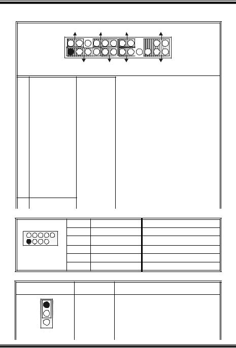
Layout of M6VLQ Pro
NOTE: ●represents the f irst pin.
1

Component Index
A.Power Source Selection for Keyboard and mouse (JKBV1)
B.Power Source Selection for USB (JUSBV1)
C.Back Panel Connector
D.ATX Po wer Connector (JATXPWR1)
E.Front Audio Head er (JAUDIO1)
F.CD Audio-In Header (JCDIN2)
G.CD Audio-In Header (JCDIN1)
H.Power Source Selection for USB (JUSBV2)
I.Digital Audio Connector (JSPDIF1)
J. Front USB Header (JUSB 2)
K.Front USB Header (JUSB 1)
L.PCI BUS Slots (PCI1-3)
M.Communication Net work Riser Slot (CNR1)
N.System Fan Header ( JSF AN1)
O.FloppyDisk Connector (FDD1)
P.Front Panel Connector (JPANEL1)
Q.Clear CMOS Function (JCMOS1)
R.Case Open Connector (JCI1)
S.IDE Connectors (IDE1-2)
T.DIMM Modules (DIMM1-2)
U.CPU Fan Head er(JCFAN 1)
V.W ake On LAN Header ( JWOL1)
2

English
M6VLQ Pro Features
A. Hardware
CPU
 Prov ides Socket 370.
 Supports Celeron™ processor PPGA (FC-PGA & FC-PGA2) and the Pentium® III Micro-Processor (FC-PGA & FC-PGA2) and VIA C3 Ezra and Ezra-T Samuel 2 for
high-end workstations and serv ers.  Front Side Bus at 66/100/133 MHz.
Chipset
 North Bridge: VIA CLE266.
 South Bridge:VIA VT8235.
Main Memory
 Supports up to 2 DDR devices.
 Supports 200/266 MHz (without ECC) DDR devices.
 Maximum memory size of 2GB.
Lan Chip (optional)
 Chip: VIA VT6103.
 Supports 10 Mb/s and 100 Mb/s auto-negotiation
 Half / Full duplex capability.
Slots
 Three 32-bit PCI bus master slots.
 One CNR slot.
On Board IDE
 Supports four IDE disk drives.
 Supports PIO Mode 4, Bride Mode and Ultra DMA 33/66/100/133 Bus Master Mode.
Super I/O
 Chip: ITE IT8705.
 Prov ides the most commonly used legacy Super I/O functionality.
  Env ironment Control initiatives
-H/W Monitor
-Fan Speed Controller
-ITE's "Smart Guardian" f unction
On Board AC’97 Sound Codec
 Chip: VIA VT1612A.
 AC’97 2.2 S/PDIF extension compliant codec.
  18-bit stereo full duplex.
3

On Board Peripherals a.Rearside
 1 serial port.
 1 VGA port.
 1 parallel port. (SPP/EPP/ECP mode)
 1 audio port in horizontal position.
 1 LAN jack.
 PS/2 mouse and PS/2 keyboard.
  2 USB2.0 ports.
b.FrontSide
1 floppy port supports 2 FDDs with 360K, 720K, 1.2M, 1.44Mand 2.88Mbytes.
4 USB2.0 ports.
 1 S/PDIF Out Connector.
Dimensions
 Micro ATX Form Factor: 19 X 24.4cm (W X L)
B. BIOS & Software
BIOS
 Award legal Bios.
 Supports APM1.2.
 Supports ACPI.
 Supports USB Function.
Software
 Supports WatchdogTM, 9th TouchTM, FLASHER™, StudioFun! TM (optional), WarpspeederTM.
 Off ers the highest performance for Windows 98 SE, Windows 2000, Windows Me, Windows XP, SCO UNIX etc.
Package contents
 HDD Cable X1
 FDD Cable X1
 User’s Manual X1
 USB Cable X1 (optional)
 Rear I/O Panel f or ATX Case X1 (optional)
 Fully Setup Driv er CD X1
 S/PDIF Cable X1 (optional)
 StudioFun! Application CD X1 (optional)
4
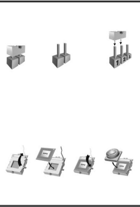
How to setup Jumper
The illustration shows how jumpers are setup. When the Jumper cap is placed on pins, the jumper is “close”. If no jumper cap is placed on the pins, the jumper is ”open”. The
illustration shows a 3-pin jumper whose pin 1and 2 are “close” when jumper cap is placed on these 2 pins.
Jumper close |
Jumper open |
Pin1-2 close |
CPU Installation
Step1: Pull the lever sideway s away from the socket and then raise the lever up to a 90-degree angle.
Step2: Look for the white dot/cut edge. The white dot/cut edge should point towards the lev er piv ot. The CPU will f it only in the correct orientation.
Step3: Hold the CPU down f irmly, and then close the lever.
Step4: Put the CPU f an on the CPU and buckle it. Connect the CPU fan power cable to the JCFAN1. This completes the installation.
Step1 |
Step2 |
Step3 |
Step4 |
5

CPU Fan Header: JCFAN1 |
|
||
|
Pin No. |
Assignment |
|
1 |
1 |
Ground |
|
2 |
+12V |
||
JCFAN1 |
|||
3 |
FAN rpm Rate Sense |
||
|
|||
System Fan Header: JSFAN1
|
|
|
|
|
|
|
|
3 |
|
1 |
Pin No. |
Assignment |
|
|
|
|
||||
|
|
1 |
Ground |
|
||
|
|
|
|
|
||
|
JSFAN1 |
|
|
|||
|
|
2 |
+12V |
|
||
|
|
|
|
3 |
FAN rpm Rate Sense |
|
|
|
|
|
|
|
|
DIMM Modules: DIMM1/ DIMM2
DRAM Access Time: 2.5V Unbuffered DDR 200/266 MHz Type required. DRAM Type: 64MB/ 128MB/ 256MB/ 512MB/ 1GB DIMM Module (184 pin)
Total Memory Size with Unbuffered DIMMs
|
|
|
|
|
|
DIMM Socket |
DDR Module |
Total Memory |
|
|
Location |
|
Size (MB) |
|
|
DIMMB1 |
64MB/128MB/256MB/512MB/1GB |
|
|
|
|
*1 |
Max is |
|
|
DIMMB2 |
64MB/128MB/256MB/512MB/1GB |
2GB |
|
|
|
*1 |
|
|
|
|
|
|
|
|
|
***Only for reference*** |
|
|
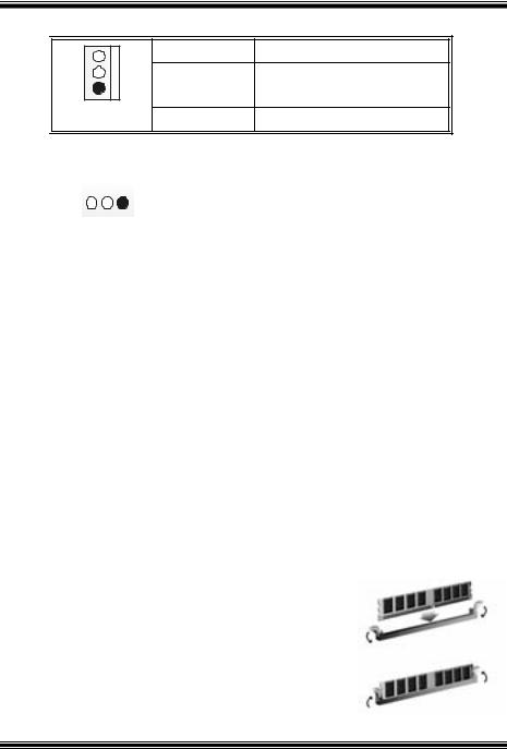
InstallingDDR Module
1.Unlock a DIMM slot by pressing the retaining clips outward. Align a DIMM on the slot such that the notch on the DIMM matches the break on the slot.
2. Insert the DIMM f irmly and vertically into the slot until the retaining chip snap back in place and the Dimm is properly seated.
6

Jumpers, Headers, Connectors & Slots
Floppy Disk Connector: FDD1
The motherboard provides a standard f loppy disk connector that supports 360K, 720K, 1.2M, 1.44M and 2.88M floppy disk types. This connector supports the
prov ided f loppy drive ribbon cables.
Hard Disk Connectors: IDE1/ IDE2
The motherboard has a 32-bit Enhanced PCI IDE Controller that provides PIO Mode 0~4, Bus Master, and Ultra DMA 33/ 66/ 100/ 133 functionality. It has two
HDD connectors IDE1 (primary) and IDE2 (secondary).
The IDE connectors can connect a master and a slave driv e, so you can connect up to f our hard disk driv es. The f irst hard drive should alway s be connected to IDE1.
Peripheral Component Interconnect Slots: PCI 1-3
This motherboard is equipped with 3 standard PCI slots. PCI stands f or Peripheral Component Interconnect, and it is a bus standard for expansion cards. This PCI
slot is designated as 32 bits.
Communication Network Riser Slot:CNR1
The CNR specification is an open Industry Standard Architecture, and it defines a hardware scalable riser card interf ace, which supports modem only.
Power Connectors: JATXPWR1
10 |
20 |
1  11
11
JATXPWR1
PIN |
Assignment |
PIN |
Assignment |
1 |
+3.3V |
11 |
+3.3V |
2 |
+3.3V |
12 |
-12V |
3 |
Ground |
13 |
Ground |
4 |
+5V |
14 |
PS_ON |
5 |
Ground |
15 |
Ground |
6 |
+5V |
16 |
Ground |
7 |
Ground |
17 |
Ground |
8 |
PW_OK |
18 |
-5V |
9 |
Standby Voltage |
19 |
+5V |
|
+5V |
|
|
10 |
+12V |
20 |
+5V |
7
Front Panel Connector: JPANEL1
|
SLP |
PWR_LED |
ON/ OFF |
IR |
|
|
(+) (+) (-) |
|
|
JPANEL1 |
2 |
|
|
24 |
1 |
|
|
2 3 |
|
|
|
|
||
|
|
(+) (-) |
|
|
|
SPK |
HLED |
R ST |
IR |
Pin |
Assignment |
Function |
1 |
+5V |
|
3 |
NA |
Speaker |
5 |
NA |
Connector |
7 |
Speaker |
|
9 |
HDD LED (+) |
Hard Drive |
11 |
HDD LED (-) |
LED |
13 |
Ground |
Reset |
15 |
Reset Control |
Button |
17 |
NA |
|
19 |
NA |
IrDA |
21 |
+5V |
Connector |
|
23 IRTX
Front USB Header: JUSB1/2
Pin |
Assignment |
Function |
2 |
Sleep Control |
Sleep |
4 |
Ground |
Button |
6 |
NA |
NA |
8 |
Power LED (+) |
POWER |
10 |
Power LED (+) |
LED |
12 |
Power LED (-) |
|
14 |
Power Button |
Power-on |
16 |
Ground |
Button |
18 |
KEY |
|
20 |
KEY |
IrDA |
22 |
Ground |
Connector |
|
||
24 |
IRRX |
|
2 |
10 |
Pin |
Assignment |
Pin |
Assignment |
|
1 |
+5V(f used) |
2 |
+5V(fused) |
|||
1 |
9 |
3 |
USBP4- |
4 |
USBP5- |
|
5 |
USBP4+ |
6 |
USBP5+ |
|||
|
|
|||||
JUSB1/2 |
|
7 |
Ground |
8 |
Ground |
|
|
|
9 |
KEY |
10 |
NA |
Power Source Selection for Keyboard/ Mouse: JKBV1
JKBV1 |
Assignment |
Description |
1 |
+5V for key board and mouse |
3 |
+5V |
Pin 1-2 close |
|
8
1 |
|
PS/2 Mouse and PS/2 Keyboard are |
|
+5V Standby |
powered with +5V standby v oltage |
3 |
|
|
Voltage |
|
Pin 2-3 close
Note: In order to support this function “Power-on the system via keyboard and mouse”, “JKBV1” jumper cap should be placed on pin 2-3.
Power Source Selection for USB: JUSBV1/ JUSBV2
|
|
|
|
|
|
|
|
|
|
|
|
JUSBV1/JUSBV2 |
Assignment |
Description |
|
|
|||
|
|
1 |
|
|
3 |
+5V |
JUSBV1: 5V for USB connectors |
|
|
|
|
|
|
|
|
||||
|
|
|
|
|
|
|
located at the JUSBLAN1 connector |
|
|
|
|
Pin 1-2 close |
|
|
|
||||
|
|
|
port |
|
|
||||
|
|
|
|
|
|
|
|
|
|
|
|
|
|
|
|
|
JUSBV2: 5V for USB connectors |
|
|
|
|
|
|
|
|
|
located at the JUSB1/2 connector ports |
|
|
|
|
1 |
|
|
3 |
+5V Standby |
JUSBV1: JUSBLAN1 port powered with |
|
|
|
|
|
|
|
|
||||
|
|
|
|
|
|
Voltage |
standby v oltage of 5V |
|
|
|
|
|
|
|
|
|
|
||
|
|
Pin 2-3 close |
|
|
|||||
|
|
|
|
|
|||||
|
|
|
JUSBV2: JUSB1/2 ports powered with |
|
|
||||
|
|
|
|
|
|
|
|
|
|
|
|
|
|
|
|
|
standby v oltage of 5V |
|
|
|
|
|
|
|
|
|
|
|
|
Note: In order to support this function “Power-on the system via USB devices”, “JUSBV1/ JUSBV2” jumper cap should be placed on pin 2-3 respectively.
Clear CMOS Jumper: JCMOS1
JCMOS1 |
Assignment |
3 |
|
1 |
Normal Operation (default) |
Pin 1-2 Close |
|
3 |
|
1 |
Clear CMOS Data |
Pin 2-3 Close |
|
9

The following procedures are for resetting the BIOS password. It is important to follow these instructions closely.
Clear CMOS Procedures:
1.Remov e AC power line.
2.Set the jumper to “Pin 2-3 Close”.
3.Wait for fiv e seconds.
4.Set the jumper to “Pin 1-2 Close”.
5.Power on the AC.
6.Reset y our desired password or clear the CMOS data.
Case Open Connector: JCI1
|
Pin |
Assignment |
1 |
1 |
Case Open Signal |
|
||
JCI1 |
2 |
Ground |
|
|
CD-ROM Audio-In Header: JCDIN1/ JCDIN2
4 |
Pin |
Assignment |
|
1 |
Left Channel Input |
1 |
2 |
Ground |
|
3 |
Ground |
JCDIN1/2 |
4 |
Right Channel Input |
Front Panel Audio Header: JAUDIO1
2 10 1
10 1

 9
9
JAUDIO1
Pin |
Assignment |
1 |
Mic In |
3 |
Mic Power |
5 |
Right Line Out/ Speaker |
|
Out Right |
7 |
Reserv ed |
9 |
Left Line Out/ Speaker |
|
Out Left |
Pin |
Assignment |
|
2 |
Ground |
|
4 |
Audio Power |
|
6 |
Right Line Out/ Speaker |
|
|
Out Right |
|
8 |
Key |
|
10 |
Left Line Out/ Speaker |
|
|
Out Left |
|
10

Digital Audio Connector: JSPDIF1
3 |
1 |
Pin |
Assignment |
1 |
+5V |
||
|
JSPDIF1 |
2 |
SPDIF_OUT |
|
|
3 |
Ground |
Wake On LAN Header: JWO L1
|
|
|
|
|
|
|
|
|
|
1 |
|
|
|
3 |
Pin |
Assignment |
|
|
|
|
|
|
||||
|
|
|
|
1 |
+5V Standby |
|
||
|
|
|
|
|
|
|
||
|
|
JWOL1 |
|
|
||||
|
|
|
2 |
Ground |
|
|||
|
|
|
|
|
|
3 |
Wake up |
|
|
|
|
|
|
|
|
|
|
Back Panel Connectors
JUSBLAN1 |
|
|
|
|
|
PS/2 |
LAN |
JPRNT1 |
JGAME1 |
||
(Optional) |
|||||
Mouse |
|
Parallel Port |
Game Port |
||
PS/2 |
USB |
COM1 |
VGA1 |
Speaker |
Mic |
Keyboard |
|
JCOM1 |
JVGA1 |
Out |
In |
JKBMS1 |
|
Line In |
|||
|
|
|
|
|
|
11

Español
Características del M6VLQ Pro
A. Hardware
CPU
 Proporciona Socket 370.
 Soporta procesador Celeron™ PPGA (FC-PGA & FC-PGA2) y Pentium® III Micro-Procesador (FC-PGA & FC-PGA2) y VIA C3 Ezra and Ezra –T Samuel 2
para estaciones de trabajo y serv idores de alta capacidad.  Front Side Bus a 66/100/133 MHz.
Chipset
 North Bridge: VIA CLE266.
 South Bridge:VIA VT8235.
Memoria Principal
 Soporta hasta 2 dispositivos DDR.
 Soporta dispositivos DDR 200/266 MHz (sin ECC).
 Tamaño máxima de memoria 2GB.
Lan Chip (opcional)
 Chip: VIA VT6103.
 Soporta 10 Mb/s y 100 Mb/s auto-negociación
 Half / Full duplex.
Ranuras
 Tres ranuras 32-bit PCI bus master.
 Una ranura CNR.
IDE Onboard
 Soporta cuatro IDE disk drives.
 Soporta Modo PIO 4, Modo Bride y Ultra DMA 33/66/100/133 Modo Bus Master.
Super I/O
 Chip: ITE IT8705.
 Proporciona el más alto f uncionamiento de uso común para Super I/O.
  Env ironment Control initiatives
-Monitor H/W
-Controlador de Velocidad del Ventilador
-Función ITE "Smart Guardian"
AC’97 Sound Codec Onboard
 Chip: VIA VT1612A.
 AC’97 2.2 S/PDIF extensión del codec.
  18-bit estéreo full duplex.
12

Periféricos Onboard a.ParteTrasera
 1 puerto en serie.
 1 puerto VGA.
 1 puerto paralelo. (modos SPP/EPP/ECP)
 1 puerto de audio enposición horizontal.
 1 LAN jack.
 Ratón PS/2 y teclado PS/2.
  2 puertos USB2.0.
b.ParteDelantera
1 puerto para disquetera soportando 2 FDDs de 360K, 720K, 1.2M, 1.44M y 2.88Mbytes.
4 puertos USB2.0.
 1 Conector S/PDIF Out.
Dimensiones
 Forma de Factor Micro ATX: 19 X 24.4cm (W X L)
B. BIOS & Software
BIOS
 Award legal Bios.
 APM1.2.
 ACPI.
ACPI.
 Función USB.
Software TM TM TM
Soporta Watchdog , 9th Touch , FLASHER™, StudioFun! (opcional), WarpspeederTM.
 Of rece el más alto funcionamiento para Windows 98 SE, Windows 2000, Windows Me, Windows XP, SCO UNIX etc.
Contenido del Paquete
 Cable HDD X1
 Cable FDD X1
 Manual del Usuario X1
 Cable USB X1 (opcional)
 Panel trasero I/O para carcasa ATX X1 (opcional)
 Conf iguración completa del CD X1
 Cable S/PDIF X1 (opcional)
 Aplicación del CD StudioFun! X1 (opcional)
13

Cómo instalar un Puente
La ilustración muestra cómo instalar un puente. Cuando el Jumper Cap está ubicado en los contactos, el puente está en “close”. Si no hay Jumper Cap ubicado en los contactos,
el puente está en ”open”. La siguiente ilustración muestra un contacto 3 en el que los contactos 1 y 2 están “close” cuando el Jumper Cap está ubicado en los dos contactos.
|
|
|
|
|
Puente open |
Puente close |
Contacto 1-2 close |
||
Instalación de la CPU
Paso 1: Empuje la palanca hacia afuera del socket y levante la palanca hasta un ángulo de 90 grados.
Paso 2: Fíjese por el punto blanco o márgen cortado. El punto blanco o márgen cortado debería apuntar hacia el piv ote de la palanca. La CPU solamente se f ijará en una sola correcta orientación.
Paso |
3: Tome el CPU f irmemente hacia abajo, y cierre la palanca para completar |
la |
|
|
instalación. |
|
|
Paso |
4: Ponga el ventilador de la CPU en el CPU y |
asegúrelo. Conecte el cable |
de |
|
corriente del v entilador de la CPU al JCFAN1. |
Ésto completa la instalación. |
|
paso1 |
paso 2 |
paso 3 |
paso4 |
14
Cabezal del Sistema de Ventilación del CPU: JCFAN1
|
Conrtacto No. |
Asignación |
|
1 |
1 |
T ierra |
|
2 |
+12V |
||
JCFAN1 |
|||
3 |
FAN rpm Rate Sense |
||
|
Cabezal del Sistema de Ventilación: JSFAN1
|
|
|
|
|
|
|
|
3 |
|
1 |
Contacto No. |
Asignación |
|
|
|
|
||||
|
|
1 |
T ierra |
|
||
|
|
|
|
|
||
|
JSFAN1 |
|
|
|||
|
|
2 |
+12V |
|
||
|
|
|
|
3 |
FAN rpm Rate Sense |
|
|
|
|
|
|
|
|
Módulos DIMM: DIMM1/ DIMM2
DRAM Tiempo de Acceso: 2.5V UnbufferedDDR 200/266 MHz Tipo requerido. DRAM Tipo: 64MB/ 128MB/ 256MB/ 512MB/ 1GB Módulo DIMM(184 contactos)
Total del Tamaño de Memoria Unbuffered DIMMs
|
|
|
|
|
|
Localización |
Módulo DDR |
Total del Tamaño |
|
|
del Socket |
|
de Memoria (MB) |
|
|
DIMM |
|
|
|
|
DIMMB1 |
64MB/128MB/256MB/512MB/1GB |
|
|
|
|
*1 |
Máximo |
|
|
DIMMB2 |
64MB/128MB/256MB/512MB/1GB |
2GB |
|
|
|
*1 |
|
|
|
|
|
|
|
|
|
***Solamente para referencia*** |
|
|
Instalación del Módulo DDR
1.Abra una ranura de DIMM presionando el clip de retención hacia af uera. Aliñe el DIMM en la ranura tales que la muesca en el DIMM encaje en la cumbrera de la ranura.
2.Inserte el DIMM v erticalmente y firmemente en
la ranura hasta que el clip de retención v uelva a su posición original y el DIMM esté correctamente colocado.
15

Puentes, Cabezales, Conectores y Ranuras
Conector de Disquetera: FDD1
La placa madre proporciona un conector estándar para disquete que soporta disquetera de 360K, 720K, 1.2M, 1.44M y 2.88M. Éste conector utiliza cables
proporcionados por el disquete.
Conector del Disco Duro: IDE1/ IDE2
La placa madre tiene un controlador de 32-bit PCI IDE que proporciona Modo PIO 0~5, Bus Master, y funcionalidad Ultra DMA 33/ 66/ 100. Tiene dos conectores
HDD: IDE1 (primario) y IDE2 (secundario).
Los conectores IDE puede conectar a un disco master y uno esclavo, así puede conectar hasta cuatro discos duros. El primer disco duro debe estar siempre conectado al IDE1.
Ranuras de Interconexión del Componente Periférico: PCI1-3
Ésta placa madre está equipada con 3 ranuras estándar PCI. PCI es la sigla para Interconexión del Componente Perif érico, y es un bus estándar para tarjetas de expansión. Ésta ranura PCI está diseñado con 32 bits.
Ranura de Banda de Suspensión de Comunicación y Red: CNR1
La especificación CNR es una abierta Industria de Arquitectura Estándar, que def ine una tarjeta de interf ace escalable del hardware en el que soporta solamente modem.
Conectores de Corriente: JATXPWR1 |
|
||||
|
|
Contactos |
Asignación |
Contactos |
Asignación |
10 |
20 |
1 |
+3.3V |
11 |
+3.3V |
|
|
2 |
+3.3V |
12 |
-12V |
|
|
3 |
Tierra |
13 |
Tierra |
|
|
4 |
+5V |
14 |
PS_ON |
|
|
5 |
Tierra |
15 |
Tierra |
|
|
6 |
+5V |
16 |
Tierra |
1 |
11 |
7 |
Tierra |
17 |
Tierra |
|
|
8 |
PW_OK |
18 |
-5V |
JATXPWR1 |
9 |
Voltaje Standby |
19 |
+5V |
|
|
+5V |
|
|
|
10 |
+12V |
20 |
+5V |
16

Conector del Panel Frontal: JPANEL1
|
|
|
SLP |
PWR_LED |
ON/ OFF |
IR |
|
||
|
|
|
|
(+) |
(+) |
(-) |
|
|
|
JPANEL1 |
2 |
|
|
|
|
|
24 |
|
|
1 |
|
|
|
|
|
2 3 |
|
||
|
|
|
|
|
|
|
|
||
|
|
|
|
|
(+) (-) |
|
|
|
|
|
|
|
SPK |
HLED |
R ST |
IR |
|
||
Contacto |
Asignación |
Función |
Contacto |
Asignación |
Función |
||||
1 |
|
+5V |
|
|
|
|
2 |
Control de |
Botón |
|
|
|
Conector |
|
|
Suspension |
de Suspension |
||
3 |
|
NA |
|
4 |
Tierra |
||||
|
del Altav oz |
|
|
||||||
5 |
|
NA |
|
|
|
|
6 |
NA |
NA |
7 |
|
Altav oz |
|
|
|
|
8 |
Corriente LED (+) |
Corriente |
9 |
HDD LED (+) |
|
LED |
|
|
10 |
Corriente LED (+) |
LED |
|
11 |
HDD LED (-) |
del Disco Duro |
|
12 |
Corriente LED (-) |
|
|||
13 |
|
Tierra |
|
Botón |
|
|
14 |
Botón de |
Botón de |
|
|
|
de Reinicio |
|
|
Encendido |
Encendido |
||
15 |
Control de |
|
16 |
Tierra |
|||||
|
|
|
|
|
|||||
|
|
Reinicio |
|
|
|
|
|
|
|
17 |
|
NA |
|
|
|
|
18 |
KEY |
|
19 |
|
NA |
|
|
|
|
20 |
KEY |
|
21 |
|
+5V |
Conector IrDA |
|
22 |
Tierra |
Conector IrDA |
||
23 |
|
IRTX |
|
|
|
|
24 |
IRRX |
|
Cabezal Frontal USB: JUSB1/2
2 |
10 |
1 |
9 |
JUSB1/2
Contactos |
Asignación |
1 |
+5V (f used) |
3 |
USBP4- |
5 |
USBP4+ |
7 |
Tierra |
9 |
KEY |
Contactos |
Asignación |
2 |
+5V (f used) |
4 |
USBP5- |
6 |
USBP5+ |
8 |
Tierra |
10 |
NA |
17

Fuente de Corriente Selección para Teclado/ Ratón: JKBV1
JKBV1 |
Asignación |
Descripción |
|
1 |
|
+5V para teclado y ratón |
|
3 |
+5V |
|
|
Contacto 1-2 close |
|
|
|
1 |
|
Ratón PS/2 y Teclado PS/2 son |
|
|
Voltaje |
encendidos con un v oltaje standby de |
|
3 |
+5V |
||
Standby +5V |
|||
|
Contacto 2-3 close
Nota: Para soportar la función “Encendiendo el sistema por medio del teclado y ratón”, el jumper cap del “JKBV1” debe ser ubicado en el contacto 2-3.
Fuente de Corriente Selección para USB: JUSBV1/ JUSBV2
|
|
|
|
|
|
|
|
|
|
|
|
JUSBV1/JUSBV2 |
Asignación |
Descripción |
|
|
|||
|
|
1 |
|
|
3 |
+5V |
JUSBV1: 5V para conectores USB |
|
|
|
|
|
|
|
|
||||
|
|
|
|
|
|
|
ubicados en el puerto JUSBLAN1 |
|
|
|
|
Contacto 1-2 close |
|
|
|
||||
|
|
|
|
|
|
||||
|
|
|
|
|
|
|
JUSBV2: 5V para conectores USB |
|
|
|
|
|
|
|
|
|
ubicado el el puerto JUSB1/2 |
|
|
|
|
1 |
|
|
3 |
Voltaje |
JUSBV1: puerto JUSBLAN1 |
|
|
|
|
|
|
|
|
||||
|
|
|
|
|
|
Standby +5V |
encendidos con voltaje standby de 5V |
|
|
|
|
|
|
|
|
|
|
||
|
|
Contacto 2-3 close |
|
|
|||||
|
|
|
JUSBV2: puertos JUSB1/2 encendidos |
|
|
||||
|
|
|
|
|
|
|
|
|
|
|
|
|
|
|
|
|
con v oltaje standby de 5V |
|
|
|
|
|
|
|
|
|
|
|
|
Nota: Para soportar la función “Encendiendo el sistema por medio del dispositivo USB”, el jumper cap del “JUSBV1/ JUSBV2” debe ser ubicado en el contacto 2-3 respectivamente.
18
Puente de Borrar CMOS: JCMOS1
JCMOS1 |
Asignación |
3 |
|
1 |
Operación Normal (default) |
Contacto 1-2 Close |
|
3 |
|
1 |
Borra datos del CMOS |
Contacto 2-3 Close |
|
Los siguientes procesos son para reiniciar la
~
contrasena del BIOS. Es importante que siga los s i g u i e n t e s p a s os c ui d a do s a m e n t e .
Procedimientos para Borrar CMOS:
1.Quite el cable de corriente del AC.
2.Fijar el puente en el “contacto 2-3 close”.
3.Espere 5 segundos.
4.Fijar el Puente en el “contacto 1-2 close”.
5.Encienda AC.
6.Reconf igure la contraseña deseada o borre datos CMOS.
Conector de la Carcasa Abierta: JCI1
|
Contactos |
Asignación |
1 |
1 |
Señal de la Carcasa Abierta |
|
||
JCI1 |
2 |
Tierra |
|
|
Cabezal de Entrada de Audio CD-ROM: JCDIN1/ JCDIN2
4 |
Contactos |
Asignación |
|
1 |
Entrada del Canal Izquierdo |
1 |
2 |
Tierra |
|
3 |
Tierra |
JCDIN1/2 |
4 |
Entrada del Canal Derecho |
19

Cabezal de Audio del Panel Frontal: JAUDIO1
2 10 1
10 1 


 9
9
JAUDIO1
Contactos |
Asignación |
1 |
Entrada del Mic |
3 |
Corriente del Mic |
5 |
Salida de Línea Derecho/ |
|
Salida del Altavoz Derecho |
7 |
Reserv ado |
9 |
Salida de Línea Izquierdo/ |
|
Salida del Altavoz Izquierdo |
Contactos |
Asignación |
|
2 |
Tierra |
|
4 |
Corriente de Audio |
|
6 |
Salida de Línea Derecho/ Salida |
|
|
del Altav oz Derecho |
|
8 |
Key |
|
10 |
Salida de Línea Izquierdo/ Salida |
|
|
del Altav oz Izquierdo |
|
Conector Digital de Audio: JSPDIF1
3 |
1 |
Contactos |
Asignación |
1 |
+5V |
||
|
JSPDIF1 |
2 |
SPDIF_OUT |
|
|
3 |
Tierra |
Conectores del Panel Trasero
|
JUSBLAN1 |
|
|
|
|
|
LAN |
JPRNT1 |
JGAME1 |
||
Raton |
(Opcional) |
||||
PS/2 |
|
Puerto Paralelo |
Puerto de Juego |
||
Teclado |
USB |
COM1 |
VGA1 |
Salida del |
Entrada |
PS/2 |
|
J COM1 |
JVGA1 |
Altavoz |
del Mic |
J KBMS1 |
|
Entrada de |
|||
|
|
|
|
Linea |
|
|
|
|
|
|
|
20

StudioFun!TM
Introduction
StudioFun!TM is a media-player based on optimized GNU/Linux distribution to bring a “Room Theater” experience into life. It plays DVD, VCD, MP3, Audio CD and other multimedia. Furthermore, Users can take snapshots of v ideo and customize the sav ed images as screensavers or photo slideshows. Of course, the images can be stored in USB mass storage devices like flash disks and USB floppy disks.
Hardware Requirements
The supported hardware list of StudioFun! updates regularly. So please check the “hwreq.txt” located in the root of StudioFun! Application Pack CD to get the latest supporting information.
Installation Procedure
Insert the “StudioFun! Application Pack CD” in a CD/DVD ROM drive and let the system boot through the CD. The disk will boot and bring up the grub boot loader installation menu. Two options are specified: “StudioFun Install” and “StudioFun Recover”.
21

StudioFun! Install
This option will do the basic installation of the distribution. The installation works on pre-installed windows or GNU/Linux distribution.
On selecting the “StudioFun Install” option the installer boots and displays a dialog box indicating the space required and waits f or a conf irmation. Selecting “Ok” will continue the installation while selecting “Cancel” will terminate the installation and reboot the machine.
If Windows or GNU/Linux is the only OS installed on the hard disk with no f ree space, it will resize the partition, either NTFS or FAT32 or ext2, and install StudioFun!. If the hard
disk has a 128MB of free space available, the installation will use the free space.
After installing the base system you will be prompted to select the resolution from the f ollowing choices
1.1024x768 (recommended)
2.800x600
3.640x480
Select the desired resolution. The default is 1024x768 f or high-end graphics.
Next y ou will be prompted to choose the DVD area/region selection code. Choose this based on the ty pe of DVDs y ou will be playing.
The installation procedure will then probe f or the ty pe of mouse installed. The distribution currently supports PS/2, USB and Serial mice. In case of serial mouse you will hav e to mov e the mouse when prompted. The other two are probed and installed automatically.
The installation procedure will now finish, the CD is ejected and a dialog box prompting to reboot the machine is display ed. Press “OK” button and enjoy StudioFun!.
3.1.1Error Messages
1.Media corrupted!! Please check the media! The CD-ROM is corrupted.
2. Extraction of base system failed!! Please try again later!! The CD-ROM is corrupted.
3.Unsupported hardware found, Aborting... If you try to install StudioFun! on an unsupported and undocumented hardware the abov e error message is popped.
4. No device found! This error message is given if there is no hard disk in the system.
22
 Loading...