


NF520-A2 SE

NF520-A2 SE /NF520-A2 Se tu p Ma nua l
FCC Inf or m at ion and Copyright
This equipment has been tes ted and found to comply with the limits of a Class
B digital device, pursuant to Part 15 of the FCC Rules. T hese limits are designed
to provide reasonable protec tion ag ai nst harmful interference in a resi dential
installation. T his equipment generates, uses , and can radiate radio frequency
energy and, if not ins talled and used in accordance with the instructions, may
cause harmful interference to radio communications. There is no guarantee
that i nte rference wil l not occur in a pa r ticula r ins ta llatio n.
The ve ndor makes no re prese n ta tio ns o r warranties wi th respec t t o t h e
contents here and specially disclaims any implied warranties of merchantability
o r fi tnes s fo r a ny p urp os e . Fu rthe r t he ve nd o r res e rves the ri g ht to rev is e t his
publication and to make changes to the c ontents here without obligation to
notify any party beforehand.
D uplic a tion o f this publicatio n, in pa rt o r in wh ol e, is no t allowed wit ho ut first
obtaining the vendor’s approval in writing.
The content of this user’s manual is subject to be c hanged without notice and
we will not be responsible for any mis takes found in this user’s manual. All the
brand and produc t names are trademarks of their respective companies .

Table of Contents
Chapter 1: Introduction .............................................1
1.1 Before You Start...................................................................1
1.2 Package Checklist................................................................ 1
1.3 Motherboard Features..........................................................2
1.4 Rea r Pa nel Co n necto rs (for Ve r 6.x) ....................................... 4
1.5 Rear Pa nel Co n necto rs (for Ve r 5 .x).......................................4
1.6 Mo t he r boa rd Layou t (NF520-A2 SE )......................................5
1.7 Mot he r boa r d La yo u t (NF520-A2).......................................... 6
Chapter 2: Hardware Installation ..............................7
2.1 Installing Ce ntral Proce ssing Unit (CPU) ................................ 7
2.2 FAN He ade rs........................................................................9
2.3 Installing Sy stem Memory.....................................................10
2.4 Con nectors a nd Slo ts............................................................12
Chapter 3: Headers & Jumpers Setup......................14
3.1 How to Se t u p Ju mper s..........................................................14
3.2 Det ail Settin gs.....................................................................14
Chapter 4: RAID Functions.......................................21
4.1 Operation Syste m................................................................21
4.2 Raid Arrays.........................................................................21
4.3 How RA I D Wor k s.................................................................21
Chapter 5: Useful Help ..............................................24
5.1 Driver Instal latio n Note.......................................................24
5.2 Award B IOS Beep Code ........................................................25
5.3 Extra Informati on ................................................................25
5.4 Troubleshooting...................................................................26
Chapter 6: WarpSpeeder™ III .................................27
6.1 Introduction........................................................................27
6.2 System Requirement............................................................27
6.3 Installation.........................................................................28
6.4 WarpSpeeder™ III................................................................29
Appendencies: SPEC In Other Language ................34
German................................................................................................34
France..................................................................................................36
Italian..................................................................................................38
Spanish................................................................................................40
Portuguese ...........................................................................................42
Polish...................................................................................................44
Russian................................................................................................46
Arabic..................................................................................................48
Japanese..............................................................................................50

NF520-A2 SE/NF520-A2
CHAPTER 1: INTRODUCTION
1.1 BEFORE YOU START
Tha nk you for choosing ou r product. Be fo re you start ins talling the
mo therboa rd , plea se make sure you fo llo w the ins tru ctio ns be lo w:
Prepare a dry and stable working environment with
s uf ficie nt ligh ting .
Always disconnect the computer from power outlet
be fo re ope ration.
Befo re yo u take the m o the rboa rd o u t from a n ti -s ta t ic
bag, ground yourself properly by touching any safely
grounded applian ce, o r use grounded wris t s trap to
remove the static charge.
Avo id tou ch ing the com pone nts o n mo the rboa rd or the
rea r side of the boa rd un les s necessa ry. Ho ld the boa rd
on the edge , do not try to be nd or flex the boa rd.
Do no t lea ve any unfas tened sma ll pa rts inside the
case after installation. Loose parts will cause short
circuits which ma y damage the equ ipment.
Keep the computer from dangerous area, such as heat
sou rce , humid air and water.
1.2 PACKAGE CHECKLIST
HDD Cable X 1
Se ria l ATA Cab le X 1
Rear I/O Panel for ATX Case X 1
Use r’s Ma nua l X 1
Fully Setup Driver CD X 1
FDD Cable X 1 (optional)
USB 2.0 Cable X1 (optional)
S/P DI F ou t C a ble X 1 (op tiona l)
Se ria l ATA Po we r Cab le X 1 (o pt io nal)
Note: The package contents may differ by area or your motherboard version.
1
Motherboard Manual
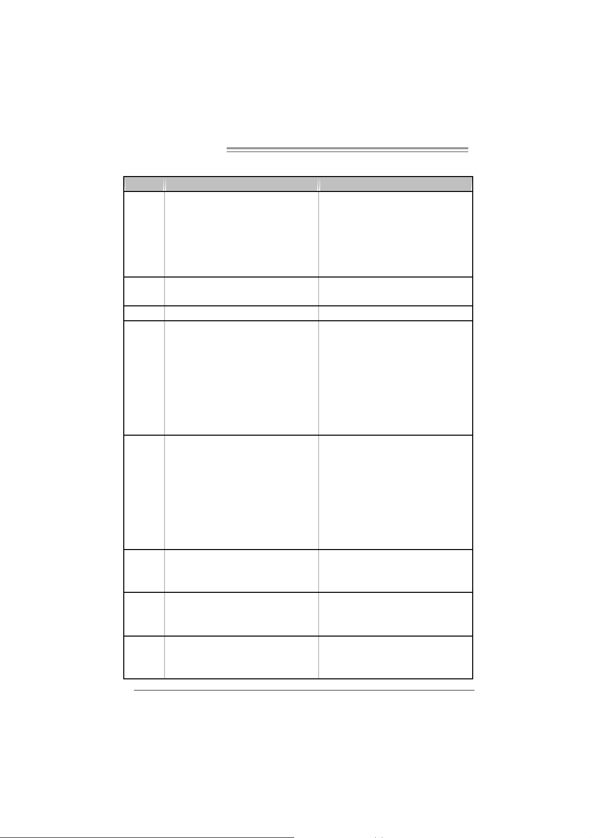
1.3 MOTHERBOARD FEATURES
NF520-A2 SE NF520-A2
Socket AM2
AM D Athlon 64 / At hl on 64 FX / Althl on 64 X 2 /
CPU
FSB
Chi pset nForce 520 nForce 520LE
Super I/O
Main
Memory
IDE
SA TA
LAN
Sempron process ors
AM D 64 Architec t ure enables 32 and 64 bit
computing
Supports Hyper Trans port and Cool=n=Quiet
Support HyperTransport
Supports up to 1GHz B andwidt h
ITE 8716F
Provides the mos t commonly used legacy Super
I/O functionality.
Low Pin Count Interfac e
Environment Control initiatives,
H/W Monitor
Fan Speed Controller
ITE's "Smart Guardian" function
DDR2 DIMM Slot x 4
Eac h DIMM s upports 256/512/1024/2048 MB
DDR2
Max Memory Capicity 8G
Dual Channel Mode DDR2 memory module
Supports DDR2 533/667/800
Registered DIMM and ECC DIMM is not
supported
Integrated IDE Controller
Ultra DMA 33 / 66 / 100 / 133 Bus M ast er Mode
supports PIO Mode 0~ 4,
Integrated Serial ATA Controller
Data transfer rates up to 3.0 Gb/s.
SATA Version 2.0 specificat ion compliant.
Realtek RTL8201CL PHY
10/100 Mb/s auto negotiat i on
Half / Full duplex capability
2
Socket AM2
AM D Athlon 64 / At hl on 64 FX / Althl on 64 X 2 /
Sempron process ors
AM D 64 Architec t ure enables 32 and 64 bit
computing
Supports Hyper Trans port and Cool=n=Quiet
Support HyperTransport
Supports up to 1GHz B andwidt h
ITE 8716F
Provides the mos t commonly used legacy Super
I/O functionality.
Low Pin Count Interfac e
Environment Control initiatives,
H/W Monitor
Fan Speed Controller
ITE's "Smart Guardian" function
DDR2 DIMM Slot x 4
Eac h DIMM s upports 256/512/1024/2048 MB
DDR2
Max Memory Capicity 8G
Dual Channel Mode DDR2 memory module
Supports DDR2 533/667/800
Registered DIMM and ECC DIMM is not
supported
Integrated IDE Controller
Ultra DMA 33 / 66 / 100 / 133 Bus M ast er Mode
supports PIO Mode 0~ 4,
Integrated Serial ATA Controller
Data transfer rates up to 3.0 Gb/s.
SATA Version 2.0 specificat ion compliant.
Realtek RTL8201CL PHY
10/100 Mb/s auto negotiat i on
Half / Full duplex capability
NF520-A2 SE/NF520-A2
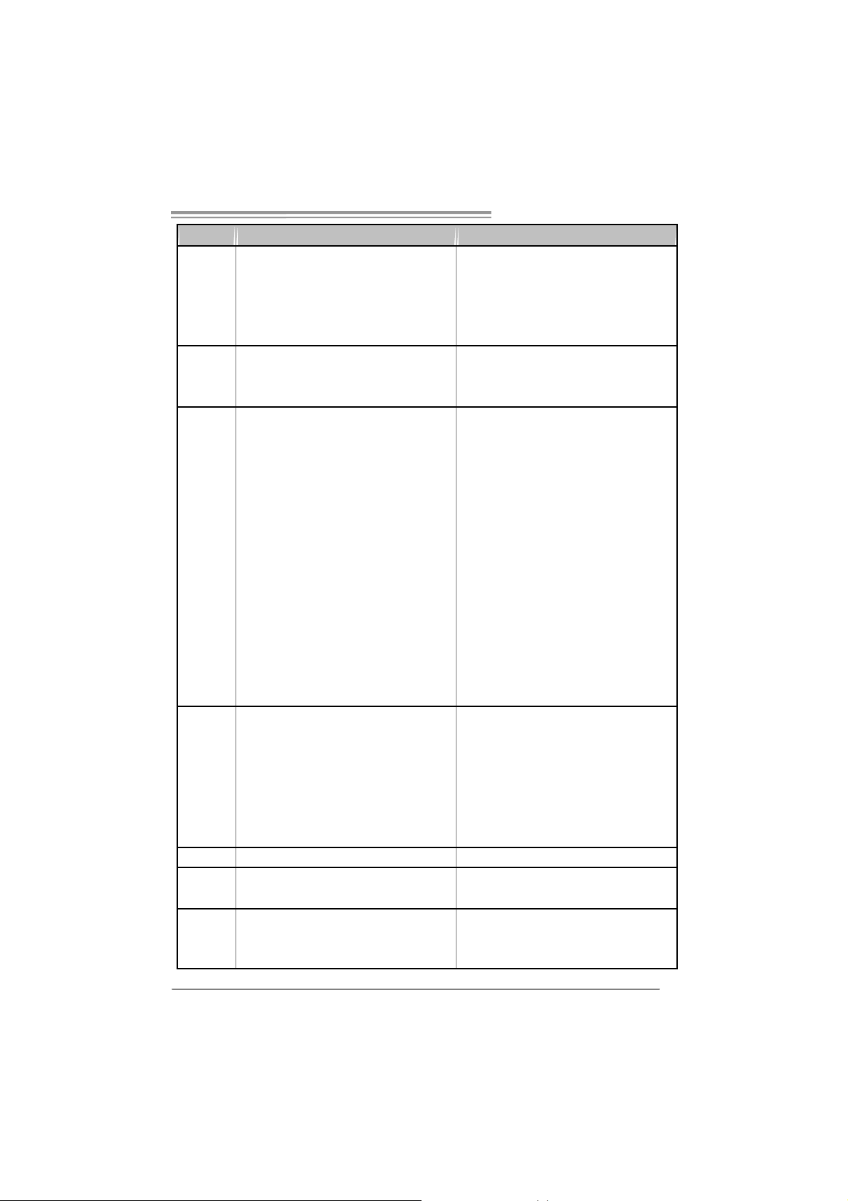
NF520-A2 SE NF520-A2
Realtek ALC861V D (Ver 6.x)
Realtek ALC888 (Ver 5.x)
Sound
slots
On Board
Connec t or
Back Panel
I/O
Board S ize 200 mm (W) x 293 mm (L) 200 mm (W) x 293 mm (L)
Special
Feature
OS S upport
5.1 channels audio out (V er 6.x)
7.1 channels audio out (V er 5.x)
Supports HD Audio
PCI s lot x3 PCI s lot x3
PCI Express x16 slot x1 PCI Expr ess x16 slot x1
PCI Express x 1 slot x2 PCI Express x 1 slot x2
Fl oppy c onnector x1 Fl oppy c onnect or x 1
Printer Port connec tor x1 Printer Port connec tor x1
IDE C onnector x1 I DE Connect or x1
SA TA Con nect or x4 SA TA C onnect or x2
Front Panel Connector x1 F ront Panel Connect or x1
Front Audio Connector x1 Front Audio C onnector x1
CD- in C onnec tor x1 C D-i n Connector x1
S/PDIF out connector x1 S/PDIF out connector x1
CP U Fa n header x1 C PU F an header x 1
Sys tem F an header x1 S ystem Fan hea der x1
USB connector x3 USB c onnector x2
Chassis open header (optional) x1 Chassis open header (optional) x1
CMOS clear header x1 CMOS clear header x1
Power Connector (24pin) x1 Power Connector (24pin) x1
Power Connector (4pin) x1 Power Connector (4pin) x1
PS/2 Keyboard x1
PS/2 Mouse x1
S e ri a l P ort x 1
LAN port x1
USB Port x4
Audio Jack (Ver 6.x) x3
Audio Jack (Ver 5.x) x6
RAID 0 / 1 / 0+ 1 support R AID 0 / 1 support
Wi ndows 2000 / XP / VISTA
Biostar Reserves the right to add or remove
support for any OS with or without notice.
Realtek ALC861V D (Ver 6.x)
Realtek ALC888 (Ver 5.x)
5.1 channels audio out (V er 6.x)
7.1 channels audio out (V er 5.x)
Supports HD Audio
PS/2 Keyboard x1
PS/2 Mouse x1
S e ri a l P ort x 1
LAN port x1
USB Port x4
Audio Jack (Ver 6.x) x3
Audio Jack (Ver 5.x) x6
Wi ndows 2000 / XP / VISTA
Biostar Reserves the right to add or remove
support for any OS with or without notice.
3
Motherboard Manual
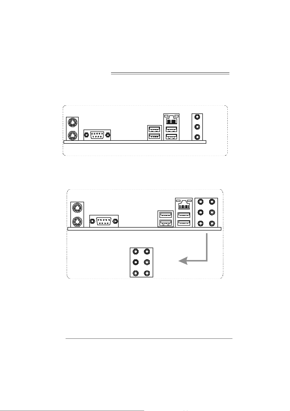
1.4 REAR PANEL CONNECTORS (FOR VER 6.X)
PS /2
Mouse
PS/ 2
Keyboard
COM1 USBX2USBX2
LAN
1.5 REAR PANEL CONNECTORS (FOR VER 5.X)
L ine In/
Surround
Lin e Out
Mic In 1/
B a ss/ C e nter
PS/2
Mouse
PS/ 2
Keyboard
COM1 USBX2USBX2
Center
Rear
Side
Line In
Line Out
Mic In
LAN
4
NF520-A2 SE/NF520-A2
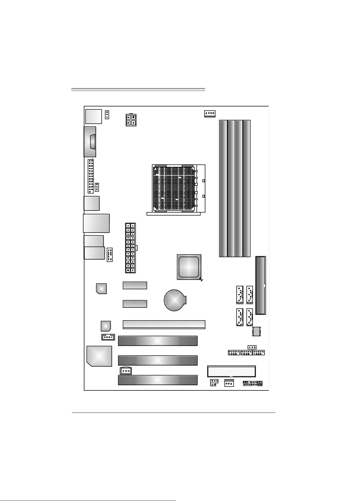
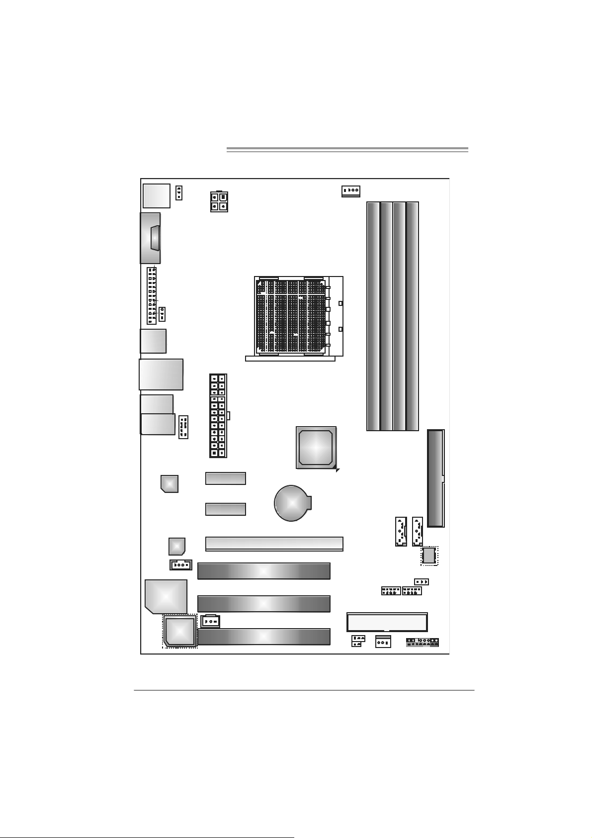
1.6 MOTHERBOARD LAYOUT (NF520-A2 SE)
JKBMS1
JCOM1
JPRNT 1
JUSB1
JUSBLAN1
JAUDIO2
(for Ver 5.x )
JAUD IO1
(for Ver 6.x)
LAN
JKBPWR1
JUSBPWR 1
JAUD IOF1
JATXPWR 2
JATXPWR 1
PEX1_1
nForce
520
Socket A M2
JCFAN1
DIMMA1
DIMMB1
SATA3 SATA4
DIMMB2
DIMMA2
IDE1
Cod ec
J CDIN1
Super I/O
Note: represents the 1■
PEX1_2
JSPDIF_ OUT1
PCI1
PCI 2
PCI3
PEX16_1
st
BAT1
pin.
JCMOS1
JCI1 (o ptional )
SATA1 SATA2
JUSBPWR2
JUSB2 JUSB3 JUSB4
FDD1
JSFAN1 JPANEL1
BI O S
5
Motherboard Manual
1.7 MOTHERBOARD LAYOUT (NF520-A2)
JKBMS1
JCOM1
JPRNT 1
JUSB1
JUSBLAN1
JAUDIO2
(for Ver 5.x )
JAUD IO1
(for Ver 6.x)
LAN
JKBPWR1
(O ptio nal)
JUSBPWR1
(O ptio nal)
JAUD IOF1
JATXPWR2
JATXPWR1
PEX1_1
nForce
520LE
Socket A M2
JCFAN1
DIMMA1
DIMMB1
DIMMB2
DIMMA2
IDE1
6
Cod ec
J CDIN1
Super I/O
BIOS
(For Ver 6. 0)
Note: represents the 1■
PEX1_2
JSPDIF_ OUT1
PCI1
PCI 2
PCI3
PEX16_1
st
BAT1
pin.
JUSBPWR 2(Optio nal)
JCMOS1
JCI1 (o ptional )
SATA1 SATA2
(F or Ver 6. 1 or a bove)
JUSB2 JUSB3
FDD1
JSFAN1 JPANEL1
BI O S
NF520-A2 SE/NF520-A2
CHAPTER 2: HARDWARE I NSTALLATION
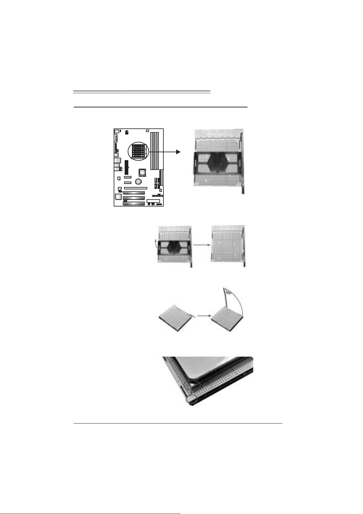
2.1 INSTALLING CEN TRAL PROCESSING UNIT (CPU)
Step 1: Remove the socket protection cap.
Step 2: Pull the lever toward direction A from the socket and then raise the
lever up to a 90-degree angle.
Step 3: Look for the white triangle on socket, and the gold triangle on
CPU should point forwards this white triangle. The CPU will fit
only in the correct orientation.
7

Motherboard Manual
Step 4: Hold the CPU down firmly, and then close the lever toward direct
B to complete the installation.
Step 5: Put the CPU Fa n on the CPU a nd buckle it. Connect the CPU
FAN power cable to the JCFAN1. This completes the installation.
8
NF520-A2 SE/NF520-A2
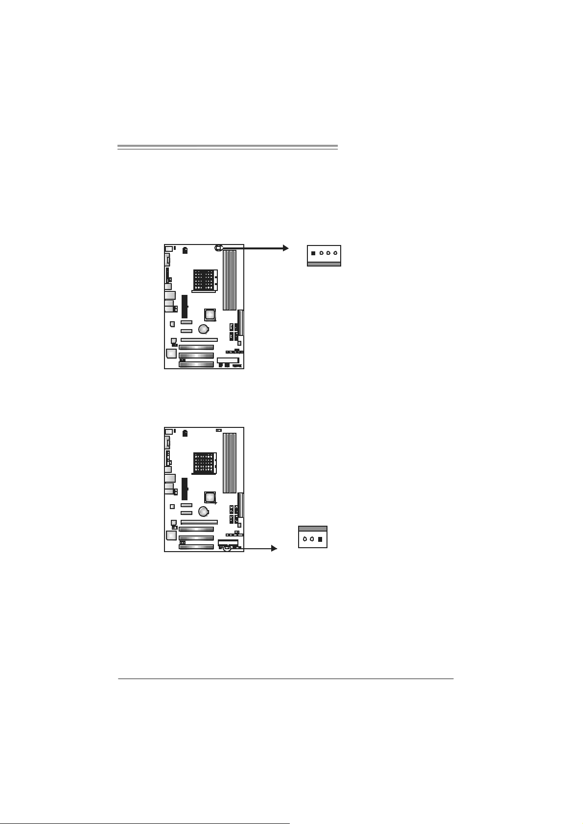
2.2 FAN HEADERS
These fan headers support cooling-fans built in the computer. The fan
cable and connector may be different according to the fan manufacturer.
Connect the fan cable to the connector while matching the black wire to
pin#1.
JCFAN1: CPU Fan Header
14
JSFAN 1: Syst e m F a n H ea der
Pin
Pin
Assignment
1 Ground
2 +12V
3 FAN RPM
rate sense
4
Smart Fan
Control
Assignment
1 Ground
2 +12V
3 FAN RPM rate
sense
13
Note:
The J CFAN1 su ppor ts 4- pi n he ad c on nec tor , an d JSFAN1s up por ts 3- pi n head c onnect or.
When co nnec ti ng wi t h wires o nto c on nect or s, pl e ase not e that t he re d wi r e i s th e p ositive
and should be c onnec ted to pi n #2, and t he blac k wire is Gr ound an d s h oul d be
conn ecte d t o GND .
9
Motherboard Manual
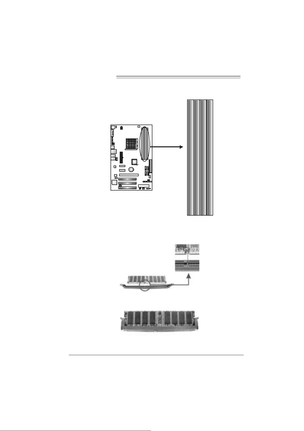
2.3 INSTALLING SYSTEM MEMORY
A. Me mo ry Modu le s
DI MMA 1
DI MMB 1
DI MMA 2
1. Unlock a DIMM slot by pressing the retaining clips outward. Align a
DIMM on the slot such that the notch on the DIMM matches the
break on the Slot.
DI MMB 2
2. Insert the DIMM vertically and firmly into the slot until the retaining
chip snap back in place and the DIMM is properly seated.
10

NF520-A2 SE/NF520-A2
B. Memory Capacity
DI MM Socket
Location
DIMMA1 256MB/512MB/1024MB/2048MB
DIMMB1 256MB/512MB/1024MB/2048MB
DIMMA2 256MB/512MB/1024MB/2048MB
DIMMB2 256MB/512MB/1024MB/2048MB
DDR2 Module
To t a l M e m o r y
Size
Max is 8 GB.
C. Dual Channel Memory installation
To trigger the Dual Channel function of the motherboard, the memory
module must meet the following requirements:
Install memory module of the same density in pairs, shown in the
following table.
Du al Channel Statu s
Enabled O O X X
Enabled X X O O
Enabled O O O O
(O means memory installed, X means memory not installed.)
The DRAM bus width of the memory module must be the same (x8 or
x16)
DIMMA1
DIMMB1 DIMMA2 DIMMB2
11
Motherboard Manual
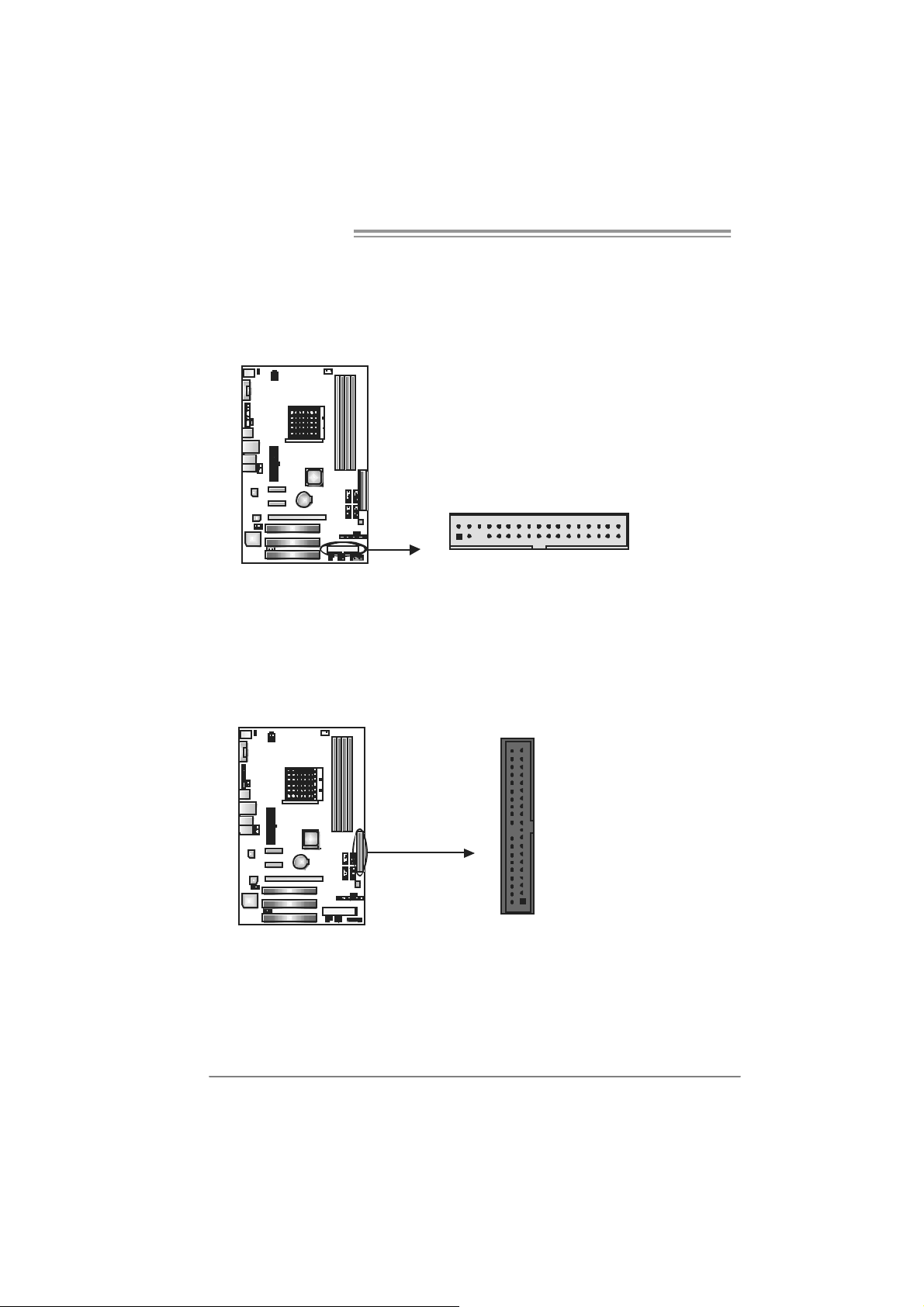
2.4 CONNECTORS AND SLOTS
FDD1: Flo ppy Disk Connector
The motherboard prov ides a standard floppy disk connector that supports 360K,
720K, 1.2M, 1.44M and 2.88M floppy disk ty pes. This connector supports the
prov ided f loppy drive ribbon cable.
IDE1: H ar d Disk C onnec tor
The motherboard has a 32-bit Enhanced PCI IDE Controller that prov ides PIO
Mode 0~4, Bus Master, and Ultra DMA 33/66/100/133 f unctionality.
The IDE connector can connect a master and a slave drive, so you can connect
up to two hard disk driv es.
2
1
21
34
33
3940
12

NF520-A2 SE/NF520-A2
PEX16_1: PCI-Express x16 Slot
- PCI-Ex press 1.0a compliant.
- Maximum theoretical realized bandwidth of 4GB/s simultaneously per
direction, f or an aggregate of 8GB/s totally.
PEX1_1/ PEX1_2: PC I-Express x1 Slots
- PCI-Ex press 1.0a compliant.
- Data transf er bandwidth up to 250MB/s per direct ion; 500MB/s in total.
- PCI-Ex press supports a raw bit-rate of 2.5Gb/s on the data pins.
- 2X bandwidth ov er the tradit ional PCI architecture.
PEX1_1
PEX1_2
PEX16_1
PCI1/PCI2/PCI3: Peri pheral Component Interconne ct Slots
This motherboard is equipped with 3 standard PCI slots. PCI stands f or
Peripheral Component Interconnect, and it is a bus standard for expansion
cards. This PCI slot is designated as 32 bits.
PCI1
PCI2
PCI3
13
Motherboard Manual
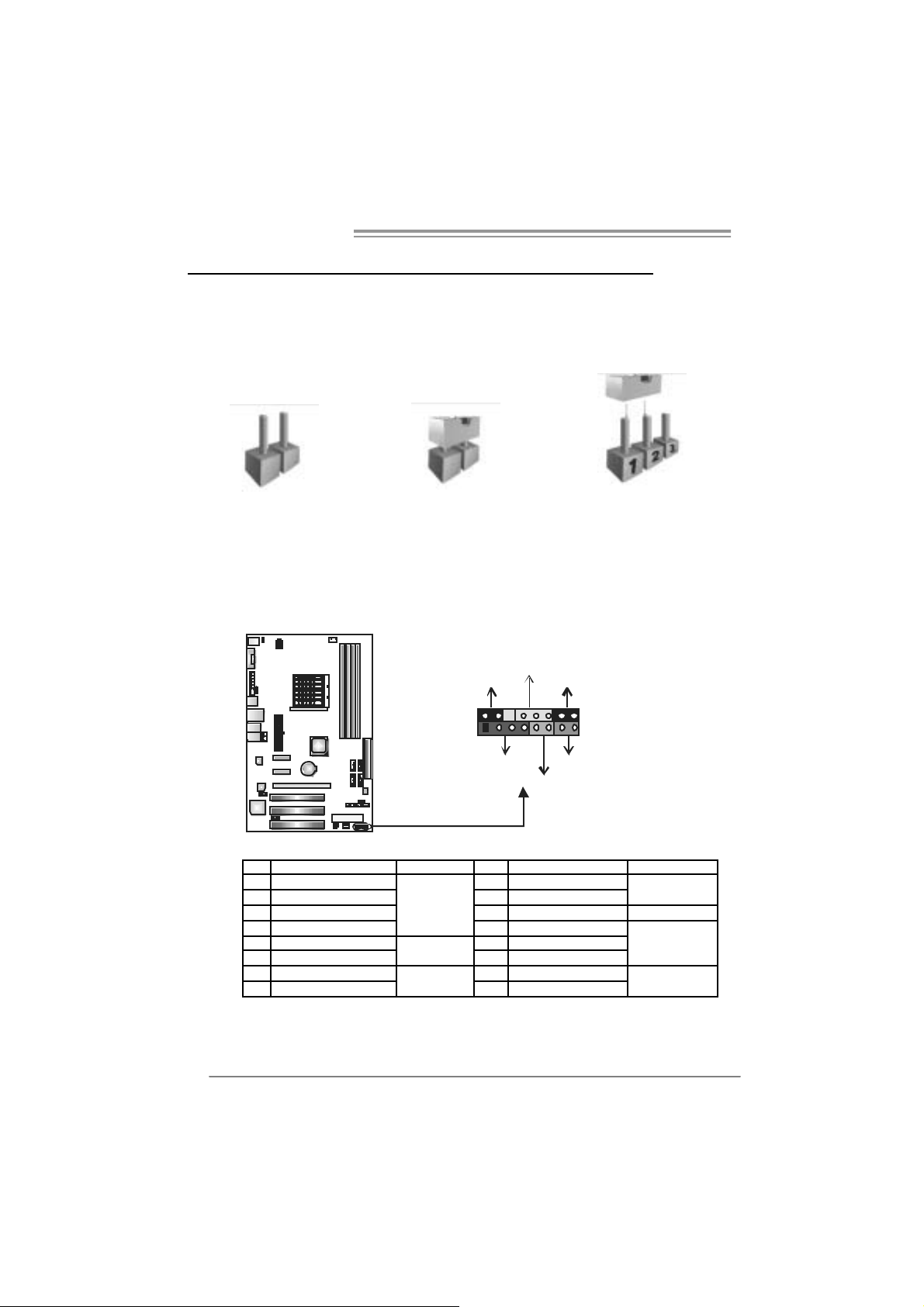
CHAPTER 3: HEADERS & JUMPERS SETUP
3.1 HOW TO SETUP JUMPERS
The illustration shows how to set up jumpers. When the jumper cap is
placed on pins, the jumper is “close”, if not, that means the jumper is
“open”.
Pin opened Pin closed Pin1-2 closed
3.2 DETAIL SETT INGS
JPANEL1: Front Panel Header
This 16-pin connector includes Power-on, Reset, HDD LED, Power LED, Sleep
button, speaker Connection. It allows user to connect the PC case’s front panel
switch functions.
PWR_L ED
SLP
9
1
SPK
++
HL E D
+
On/ Off
-
-
RST
16
8
14
Pin Assignment Functio n Pin Assignment Function
1 +5V 9 Sleep control
2 N/A 10 Ground
3 N/A 11 N/A N/A
4 Speaker
5 HDD LED (+) 13 Power LED (+)
6 HDD LED (-)
7 Ground 15 Power button
8 Reset control
Speaker
Connector
Hard drive
LED
Reset button
12 Po we r LED (+)
14 Po we r LED (-)
16 Ground
Sleep button
Power LED
Power-on button
 Loading...