


NF520-A2 TE/NF520-A2 SE/NF520-A2 BIOS Setup
BIOS Setup ................................................................................................ |
1 |
|
1 Main Menu ............................................................................................. |
3 |
|
2 |
Standard CMOS Features..................................................................... |
7 |
3 Advanced BIOS Features ...................................................................... |
9 |
|
4 Advanced Chipset Features................................................................. |
16 |
|
5 |
Integrated Peripherals......................................................................... |
19 |
6 |
Power Management Setup................................................................... |
26 |
7 |
PnP/PCI Configurations...................................................................... |
30 |
8 |
PC Health Status .................................................................................. |
33 |
9 |
Performance Booster Zone.................................................................. |
35 |
i

NF520-A2 TE/NF520-A2 SE/NF520-A2
BIOS Setup
Introduction
The purpose of this manual is to describe the settings in the Phoenix-Award™ BIOS Setup program on this motherboard. The Setup program allows users to modify the basic system configuration and save these settings to CMOS RAM. The power of CMOS RAM is supplied by a battery so that it retains the Setup information when the power is turned off.
Basic Input-Output System (BIOS) determines what a computer can do without accessing programs from a disk. This system controls most of the input and output devices such as keyboard, mouse, serial ports and disk drives. BIOS activates at the first stage of the booting process, loading and executing the operating system. Some additional features, such as virus and password protection or chipset fine-tuning options are also included in BIOS.
The rest of this manual will to guide you through the options and settings in BIOS Setup.
Plug and Play Support
This PHOENIX-AWARD BIOS supports the Plug and Play Version 1.0A specification and ESCD (Extended System Configuration Data) write.
EPA Green PC Support
This PHOENIX-AWARD BIOS supports Version 1.03 of the EPA Green PC specification.
APM Support
This PHOENIX-AWARD BIOS supports Version 1.1&1.2 of the Advanced Power Management (APM) specification. Power management features are implemented via the System Management Interrupt (SMI). Sleep and Suspend power management modes are supported. Power to the hard disk drives and video monitors can also be managed by this PHOENIX-AWARD BIOS.
1

NF520-A2 TE/NF520-A2 SE/NF520-A2
ACPI Support
Phoenix-Award ACPI BIOS support Version 1.0b of Advanced Configuration and Power interface specification (ACPI). It provides ASL code for power management and device configuration capabilities as defined in the ACPI specification, developed by Microsoft, Intel and Toshiba.
PCI Bus Support
This PHOENIX-AWARD BIOS also supports Version 3.0 of the Intel PCI (Peripheral Component Interconnect) local bus specification.
DRAM Support
DDR2 SDRAM (Double Data Rate Synchronous DRAM) is supported.
Supported CPUs
This PHOENIX-AWARD BIOS supports the AMD CPU.
Using Setup
Use the arrow keys to highlight items in most of the place, press <Enter> to select, use the <PgUp> and <PgDn> keys to change entries, press <F1> for help and press <Esc> to quit. The following table provides more detail about how to navigate in the Setup program by using the keyboard.
Keystroke |
Function |
Up arrow |
Move to previous item |
Down arrow |
Move to next item |
Left arrow |
Move to the item on the left (menu bar) |
Right arrow |
Move to the item on the right (menu bar) |
Move Enter |
Move to the item you desired |
PgUp key |
Increase the numeric value or make changes |
PgDn key |
Decrease the numeric value or make changes |
+ Key |
Increase the numeric value or make changes |
- Key |
Decrease the numeric value or make changes |
Esc key |
Main Menu – Quit and not save changes into CMOS |
|
Status Page Setup Menu and Option Page Setup Menu – Exit |
|
Current page and return to Main Menu |
F1 key |
General help on Setup navigation keys |
F5 key |
Load previous values from CMOS |
F7 key |
Load the optimized defaults |
F10 key |
Save all the CMOS changes and exit |
2
NF520-A2 TE/NF520-A2 SE/NF520-A2
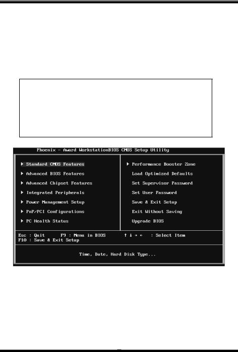
1 Main Menu
Once you enter Phoenix-Award BIOS™ CMOS Setup Utility, the Main Menu will appear on the screen. The Main Menu allows you to select from several setup functions. Use the arrow keys to select among the items and press <Enter> to accept and enter the sub-menu.
!! WARNING !!
For better system performance, the BIOS firmware is being continuously updated. The BIOS information described in this manual (Figure 1, 2, 3, 4, 5, 6, 7, 8, 9) is for your reference only. The actual BIOS information and settings on board may be slightly different from this manual.
Figure 1: Main Menu
Standard CMOS Features
This submenu contains industry standard configurable options.
3

NF520-A2 TE/NF520-A2 SE/NF520-A2
Advanced BIOS Features
This submenu allows you to configure advanced features of the BIOS.
Advanced Chipset Features
This submenu allows you to configure special chipset features.
Integrated Peripherals
This submenu allows you to configure certain IDE hard drive options and Programmed Input/ Output features.
Power Management Setup
This submenu allows you to configure the power management features.
PnP/PCI Configurations
This submenu allows you to configure certain “Plug and Play” and PCI options.
PC Health Status
This submenu allows you to monitor the hardware of your system.
Performance Booster Zone
This submenu allows you to change CPU Vcore Voltage and CPU/PCI clock. (However, we suggest you to use the default setting. Changing the voltage and clock improperly may damage the CPU or M/B!)
Load Optimized Defaults
This selection allows you to reload the BIOS when problem occurs during system booting sequence. These configurations are factory settings optimized for this system. A confirmation message will be displayed before defaults are set.
4
NF520-A2 TE/NF520-A2 SE/NF520-A2
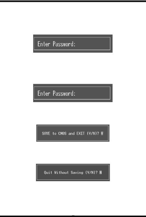
Set Supervisor Password
Setting the supervisor password will prohibit everyone except the supervisor from making changes using the CMOS Setup Utility. You will be prompted with to enter a password.
Set User Password
If the Supervisor Password is not set, then the User Password will function in the same way as the Supervisor Password. If the Supervisor Password is set and the User Password is set, the “User” will only be able to view configurations but will not be able to change them.
Save & Exit Setup
Save all configuration changes to CMOS (memory) and exit setup. Confirmation message will be displayed before proceeding.
Exit Without Saving
Abandon all changes made during the current session and exit setup. Confirmation message will be displayed before proceeding.
5

NF520-A2 TE/NF520-A2 SE/NF520-A2
Upgrade BIOS
This submenu allows you to upgrade bios.
6
NF520-A2 TE/NF520-A2 SE/NF520-A2
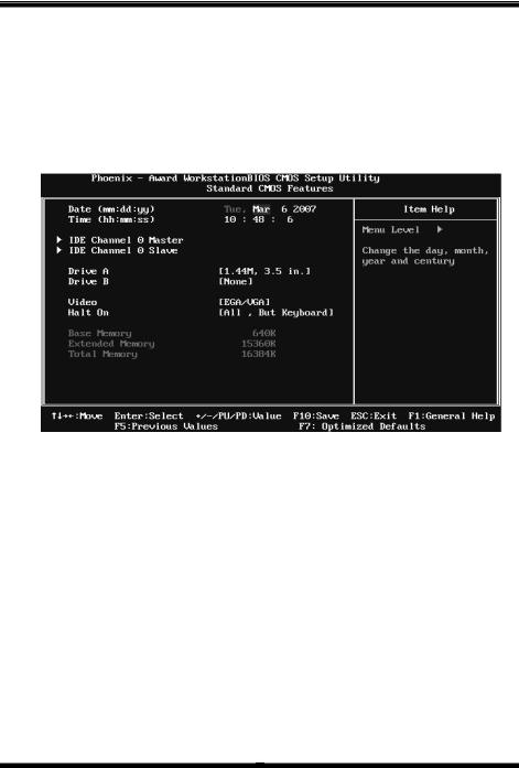
2 Standard CMOS Features
The items in Standard CMOS Setup Menu are divided into several categories. Each category includes no, one or more than one setup items. Use the arrow keys to highlight the item and then use the<PgUp> or <PgDn> keys to select the value you want in each item.
Figure 2: Standard CMOS Setup
Main Menu Selections
This table shows the items and the available options on the Main Menu.
Item |
Options |
Description |
|
|
|
Set the system date. Note |
|
Date |
mm : dd : yy |
that the ‘Day’ automatically |
|
changes when you set the |
|||
|
|
||
|
|
date. |
|
Time |
hh : mm : ss |
Set the system internal |
|
clock. |
|||
|
|
||
IDE Channel 0 Master |
Options are in its sub |
Press <Enter> to enter the |
|
sub menu of detailed |
|||
menu. |
|||
|
options |
||
|
|
||
IDE Channel 0 Slave |
Options are in its sub |
Press <Enter> to enter the |
|
sub menu of detailed |
|||
menu. |
|||
|
options. |
||
|
|
7

NF520-A2 TE/NF520-A2 SE/NF520-A2
Item |
Options |
Description |
|
|
360K, 5.25 in |
|
|
|
1.2M, 5.25 in |
Select the type of floppy |
|
Drive A |
720K, 3.5 in |
||
disk drive installed in your |
|||
Drive B |
1.44M, 3.5 in |
||
system. |
|||
|
2.88M, 3.5 in |
||
|
|
||
|
None |
|
|
|
EGA/VGA |
Select the default video |
|
Video |
CGA 40 |
device. |
|
|
|||
CGA 80 |
|
||
|
|
||
|
MONO |
|
|
|
All Errors |
|
|
|
No Errors |
Select the situation in which |
|
Halt On |
All, but Keyboard |
you want the BIOS to stop |
|
the POST process and |
|||
|
All, but Diskette |
||
|
notify you. |
||
|
All, but Disk/ Key |
|
|
Base Memory |
N/A |
Displays the amount of |
|
conventional memory |
|||
|
|
detected during boot up. |
|
|
|
Displays the amount of |
|
Extended Memory |
N/A |
extended memory detected |
|
|
|
during boot up. |
|
Total Memory |
N/A |
Displays the total memory |
|
available in the system. |
|||
|
|
||
|
|
|
8

NF520-A2 TE/NF520-A2 SE/NF520-A2
3 Advanced BIOS Features
Figure 3: Advanced BIOS Setup
Cache Setup
9
NF520-A2 TE/NF520-A2 SE/NF520-A2
CPU Internal Cache
Depending on the CPU/chipset in use, you may be able to increase memory access time with this option.
Enabled (default) Enable cache.
Disabled |
Disable cache. |
External Cache
This option enables or disables “Level 2” secondary cache on the CPU, which may improve performance.
Enabled (default) Enable cache.
Disabled |
Disable cache. |
Boot Seq & Floppy Setup
This item allows you to setup boot sequence & Floppy.
10
NF520-A2 TE/NF520-A2 SE/NF520-A2
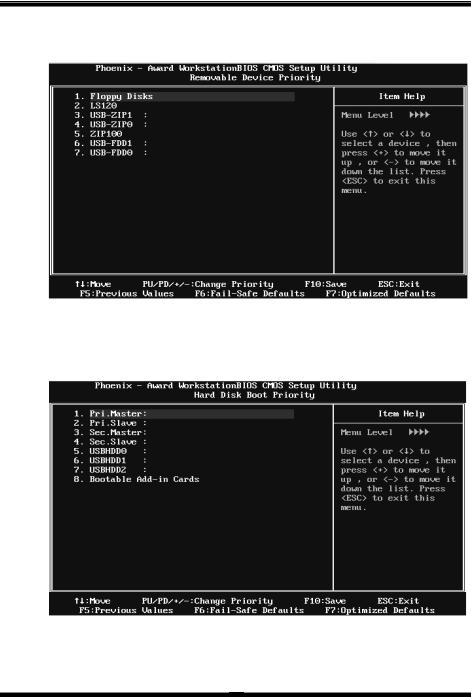
Removable Device Priority
Select Removable Boot Device Priority.
The Choices: Floppy Disks, Zip100, USB-FDD0, USB-FDD1, USB-ZIP0,
USB-ZIP1, LS120.
Hard Disk Boot Priority
The BIOS will attempt to arrange the Hard Disk boot sequence automatically. You can change the Hard Disk booting sequence here.
The Choices: Pri. Master, Pri. Slave, Sec. Master, Sec. Slave, USB HDD0, USB HDD1, USB HDD2, and Bootable Add-in Cards.
11
 Loading...