


A780L

A780L M2G+/A780L M2L+/A780L BIOS Man u al
i
B IOS Setup.... ............ ............ ............ ............ ........................ ............ .........1
1 Main Menu...............................................................................................3
2 Adv an ced Menu.................. ............ .................................... ............ .........6
3 PCIPnP Me nu........................................................................................16
4 Boot Menu..............................................................................................19
5 Chipset Menu.........................................................................................21
6 Performance Me nu ...............................................................................29
7 Exit Menu...............................................................................................38

A780L M2G+/A780L M2L+/A780L BIOS Man u al
BIOS Setup
Introducti on
The purpose of this manual is to describe the settings in the AMI BIOS Setup
program on this motherboard. The Setup program allows users to modify the basic
system configuration and save these settings to CMOS RAM. The power of CMOS
RAM is supplied by a battery so that it retains the Setup information when the power
is turned off.
Basic Input-Output System (BIOS) determines what a computer can do without
accessing programs from a disk. This system controls most of the input and output
devices such as keyboard, mouse, serial ports and disk drives. B IOS activates at the
first stag e o f the booting proc ess, loading and executing the operating syst em. Som e
additional features, such as virus and password protection or chipset fine-tuning
options are also included in BIOS .
T he rest of this manual will to guide you through the options and settings in BIOS
Setup.
Plug and Play Support
T his AMI BIOS supports the P lug and Play Version 1.0A specific ation.
EPA Green PC Support
T his AMI BIOS supports Version 1.03 of t he EPA Green PC specification.
APM Support
This AMI BIOS supports Version 1.1&1.2 of the Advanced Power Management
(AP M) speci fic ati on. Power m anagement featu res a re im pl ement ed via t he S ystem
Management Interrupt (SMI). Sleep and Suspend power management modes are
supported. Power to the hard disk drives and video monitors can also be m anaged by
this AMI B IOS.
ACPI Supp ort
AMI ACPI BIOS support Version 1.0/2.0 of Advanced Configuration and Power
interfa ce specifi cation (ACP I). It provides ASL code for pow er manag ement and
device configuration capabilities as defined in the ACPI specification, developed by
Microso ft, Intel and T oshiba.
1
A780L M2G+/A780L M2L+/A780L BIOS Man u al
PCI Bus Support
T his AMI BIOS also supports Version 2. 3 of the Intel PCI (Peripheral Component
Int erconn ect ) local b us speci ficati on .
DRA M Support
DDR2 S DRAM (Double Data Rate II S ynchronous DRAM) is supported.
Su ppor t e d CP Us
T his AMI BIOS supports the AMD CPU.
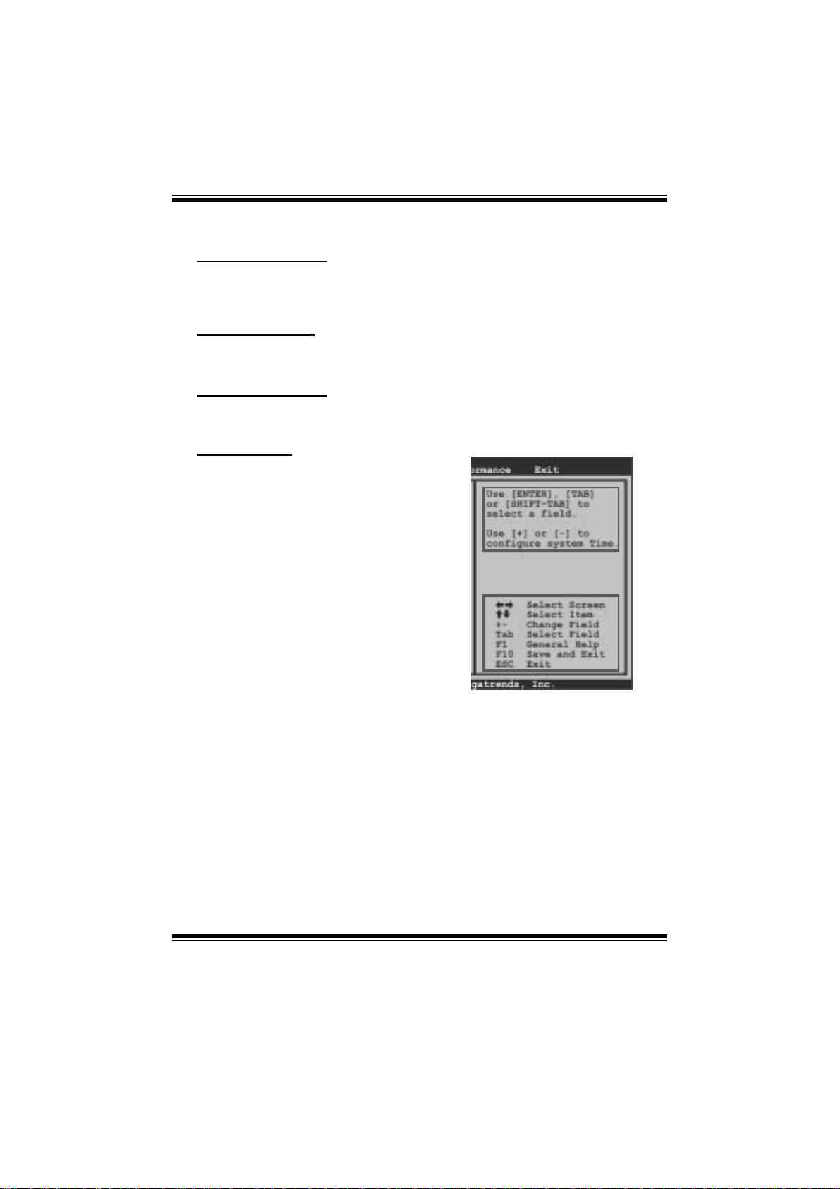
Using Setup
When starting up the computer, press
<Del> during the Power-On Self-Test
(POST) to enter the BIOS setup utility.
In the BIOS setup utility, you will see
General Help description at the top right
corner, and this is providing a brief
description of the selected item.
Navigation Keys for that particular menu
are at the bottom right corner, and you can
us e these k eys to s ele ct item and ch ange
the settings.
Notice
z T he default BIOS settings apply for most conditions to ensure optimum performan ce
of the motherboard. If the system becomes unstable after changing any settings,
please load the default settings to ensure system’s compatibility and stability. Use
Load Setup Default under the Exi t Menu.
z For better system per form ance, the BIOS firmware is being continuously updated.
T he BIOS inform ation described in thi s manual is for your refer ence only. The act ual
BIOS i nformation and settings on board may be slightly different from this manual.
z T he content of this manual is subject to be changed without notice. We will not be
responsible for any mistakes found in this user’s manual and any system damage t hat
may be caused by wrong-settings.
General Help
Navigati on Keys
2
A780L M2G+/A780L M2L+/A780L BIOS Man u al
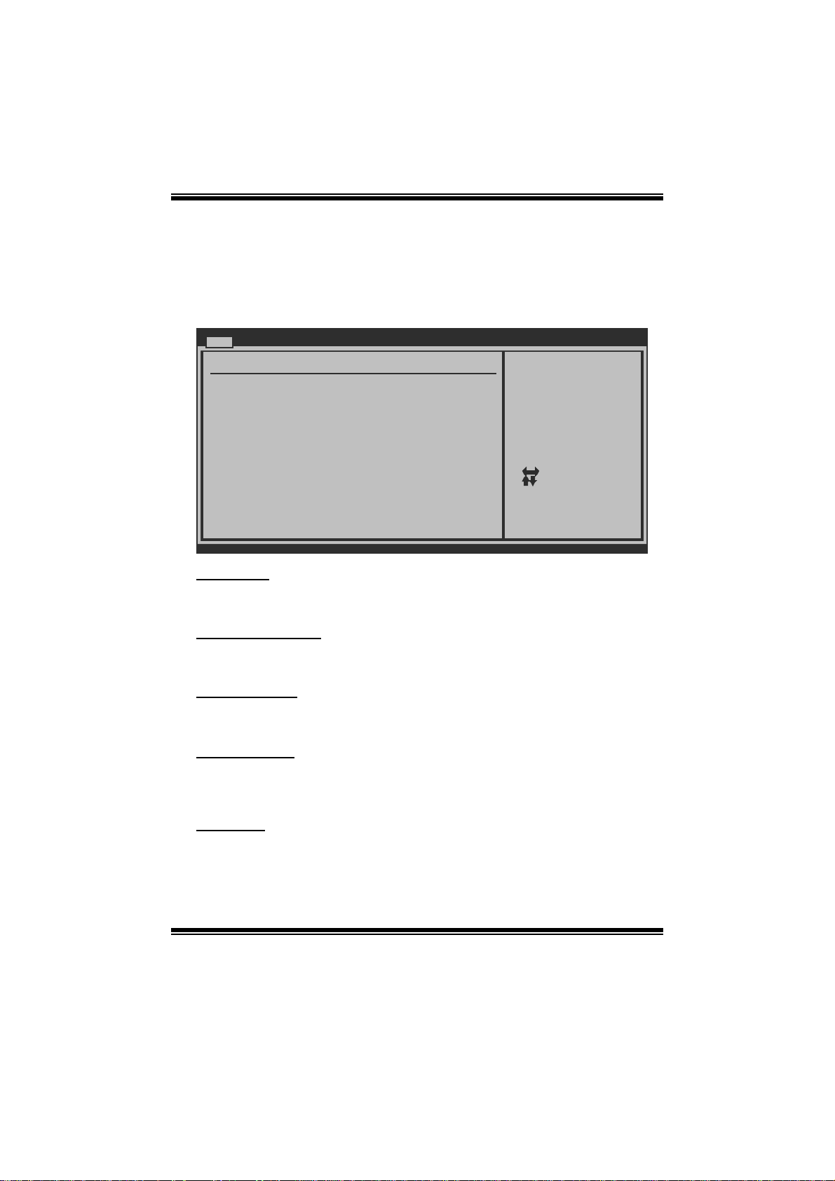
1 Main Menu
Once you enter AMI BIOS Setup Utility, the Main Menu will appear on the screen
providing an overview of the basic system inform ation.
Main Advanced PCIPnP Boot Chipset Performance
System Overview
AMI BIOS
Version :01.01.0 1
Build Date:01/01/0 9
System Memory
Size :
System Time [ :00:00]00
System Date [Thu 01/01/2009]
Floppy A
> IDE Configuratio n
vxx.xx (C)Copyright 198 5-200x, Amer ican Megatrends, Inc.
AM I BIOS
BIOS SETUP UTILITY
Exit
Use [ENTER], [TA B]
or [SHIFT-TAB] t o
select a field.
Use [+] or [-] t o
configure system Time.
Select Screen
Select Item
Change Field
+-
Select Field
Tab
General Help
F1
Save and Exit
F10
Exit
ESC
Shows s ystem i nformation including BIOS version and built date.
System Memory
Shows s ystem m emory size, VGA shard memory will be excluded..
System Ti me
Set the system internal clock.
System Date
Set the system date. Note that the ‘Day’ automatically changes when you set the
date.
Floppy A
Select the type of floppy disk drive installed in your system.
Options: 360K, 5.25 in / 1.2M, 5.25 in / 720K, 3.5 in / 1.44M, 3. 5 in /
2.88M, 3.5 in / None
3
A780L M2G+/A780L M2L+/A780L BIOS Man u al
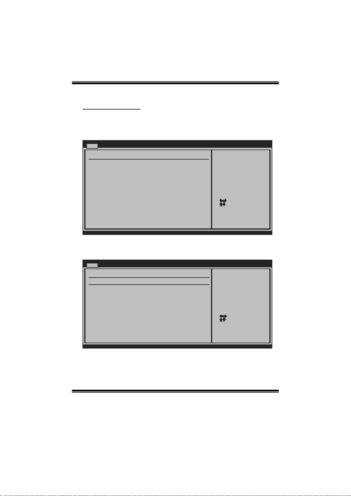
IDE Configuration
Th e BIO S w i ll au t o m aticall y d et ect t h e presen ce of ID E / SAT A d evices . Th ere i s a
su b-menu fo r each IDE/ SAT A devi ce. S elect a devi ce and pres s < Ent er> t o enter
the sub-menu of detailed options.
Main
IDE Confuguration
> Primary IDE Mast er
> Primary IDE Slav e
> SATA 1 Device
> SATA 2 Device
> SATA 3 Device
> SATA 4 Device
Hard Disk Write Pr otect [ Disabled]
IDE Detect Time Ou t (Sec) [ 35]
BIOS SETUP UTILITY
While entering s etup,
BIOS auto detect s the
presence of IDE
devices. This di splays
the status of au to
detection of IDE
devices.
Select Screen
Select Item
Go to Sub Scr een
Enter
General Help
F1
Save and Exit
F10
Exit
ESC
vxx.xx (C)Copyright 198 5-200x, Amer ican Megatrends, Inc.
Primary IDE Master/Slav e ; SATA 1/2/3/4/5/6 Device
Main
Primary IDE Master
Device :
Type [Auto]
LBA/Large Mode [Auto]
Block (Multi-Sector Transfer)[Auto]
PIO Mode [Auto]
DMA Mode [Auto]
S.M.A.R.T [Auto]
32Bit Data Transfer [Enabled]
vxx.xx (C)Copyright 1985-200x, American Megatrends, Inc.
BIOS SETUP UTILITY
Select the type
of device connected
to the system.
Select Screen
Select Item
Change Option
+-
General Help
F1
Save and Exit
F10
Exit
ESC
The BIOS detects the information and values of respective devices, and these
information and values are shown below to t he nam e of the sub-m enu.
4

A780L M2G+/A780L M2L+/A780L BIOS Man u al
Type
Select the type of the IDE/SAT A drive.
Options: Auto (Default) / C DROM / ARMD / Not Installed
LBA/Large Mode
Enable or disable the LBA mode.
Options: Auto (Default) / Disabled
Block (Multi-Sector Transfer)
En able o r d i s ab l e m u l ti -s ect or t ran s fer.
Options: Auto (Default) / Disabled
PIO Mode
Select the P IO m ode.
Options: Auto (Default) / 0 / 1 / 2 / 3 / 4
DMA Mode
Select the DMA mode.
Opti ons: Auto (Defaul t) / S WDMA0 ~ 2 / MWDMA0 ~ 2 / UDMA0 ~ 5
S.M.A.R.T
Set the Smart Monitoring, Analysis, and Reporting Technology.
Options: Auto (Default) / Disabled / Enabled
32Bit Data Trans fer
Enable or disable 32-bit data transfer.
Options: Enabled (Default) / Disabled
Har d Disk Wri te Protec t
Disable or enable device write protection. This will be effective only if the device
is accessed through BIOS.
Options: Disabled (De fault) / Enabled
IDE Detect Time Out (Sec)
Select the time out value for detecting IDE/SAT A devices.
Options: 35 (Default) / 30 / 25 / 20 / 15 / 10 / 5 / 0
5
A780L M2G+/A780L M2L+/A780L BIOS Man u al
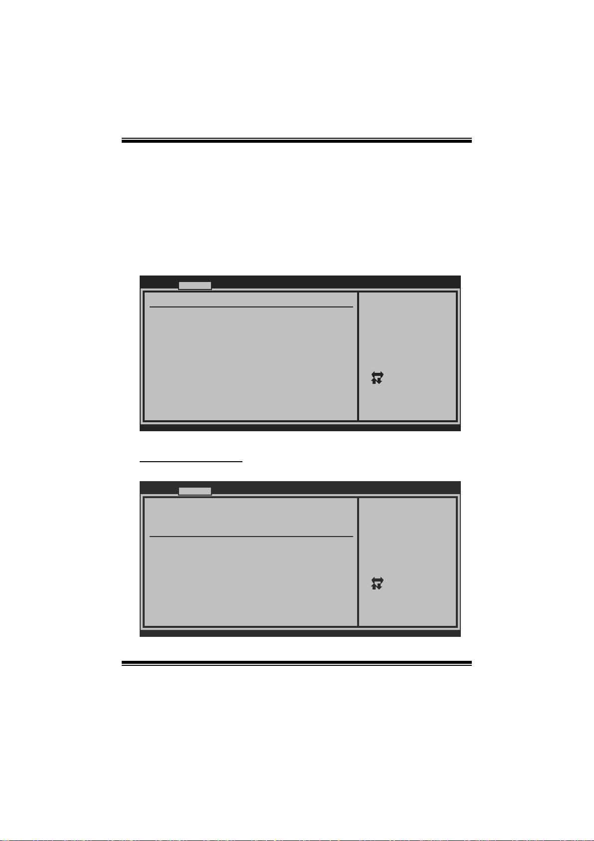
2 Advanced Menu
T he Advanced Menu allows you to configure t he settings of CP U, Super I/O, P ower
Management, and other system devices.
Notice
z Beware of that setting inappropriate values in items of this menu may cause
system to malfunction.
Main Advanced PCIPnP Boot Chipset Performance
WARNING: Setti ng wrong values in below sections
may c ause system to malfunction.
> CPU Configur ation
> SuperIO Conf iguration
> Smart Fan Co nfiguration
> Hardware Hea lth Configuration
> Power Config uration
> USB Configur ation
BIOS SETU P UTILITY
Configure CPU.Advanced Setti ngs
Exit
Se lect Screen
Se lect Item
Go to Sub Screen
Enter
Ge neral Help
F1
Sa ve and Exit
F10
Exit
ESC
vxx .xx (C)Copyright 1985-200x, American Meg atrends, Inc.
CPU Configuration
T his item shows the CPU information that the BIOS automatically detects.
Advanced
CPU Configuration
Module Version:
AGESA Version:
Physical Count:
Logical Count:
AMD CPU
Revision:
Cache L1:
Cache L2:
Cache L3:
Speed : NB Clk:
ncHT Speed : Width I/O :
Able to Change Fre q :
uCode Patch Level :
Secure Virtual Mac hine Mode [ Enabled]
PowerNow [ Enabled]
ACPI SRAT Table [ Enabled]
CPU Prefetching [ Enabled]
vxx.xx (C)Copyright 198 5-200x, Amer ican Megatrends, Inc.
BIOS SETUP UTILITY
6
Enable/Disable
Secure Virtual M achine
Mode (SVM)
Select Screen
Select Item
+-
Change Option
F1
General Help
F10
Save and Exit
Exit
ESC

A780L M2G+/A780L M2L+/A780L BIOS Man u al
Secure Vi r t ual Machine Mode
Virtualization Technology can virtually separate your system resource into several
parts, thus enhance the performance when running virtual machines or multi
interfa ce systems.
Options: Enabled (Default) / Disabled
PowerNow
T his item allows you t o enable or disable the PowerNow power saving technology.
Options: Enabled (Default) / Disabled
ACPI SRAT Tabl e
Th e operat i n g sy s t em scans t h e ACPI SRAT at b oot t im e and u s es th e i nformatio n t o
better allocate memory and schedule software threads for maximum performance.
This item controls whether the SRAT is made available to the operating system at
boot up, or not.
Options: Enabled (Default) / Disabled
CPU Prefetching
T his item allows you t o enable or disable CPU Prefetching fun ction.
Options: Enabled (Default) / Disabled
Probe Filter
T his item allows you t o set ini tialization mode for Probe Filt er.
Options: Auto (Default) / Disabled / MP Mode
C1E Support
C1E is “Enhanced Halt State” function, this function helps to save power and
decr ease heat by lowering CPU frequen cy while the processor is not working.
Options: Enabled (Default) / Disabled
7

A780L M2G+/A780L M2L+/A780L BIOS Man u al
S uperI O Co n f i gurati on
Advan ced
Configure ITE8 718 Super IO Chipset
Onboard Floppy Controller [Enabled]
Serial Port1 A ddress [3F8/IRQ4]
Parallel Port Address [378]
Parallel Por t Mode [Normal]
Parallel Por t IRQ [IRQ7]
Keyboard Power On [Disabled]
Mouse PowerOn [Disabled]
Restore on AC Power Loss [Power Off]
BIOS SETU P UTILITY
Allows BIOS to Enable
or Disable Floppy
Controller
Se lect Screen
Se lect Item
Ch ange Option
+-
Ge neral Help
F1
Sa ve and Exit
F10
Exit
ESC
vxx .xx (C)Copyright 1985-200x, American Meg atrends, Inc.
Onboard Floppy Controller
Select enabled if your system has a floppy disk controller (FDC) installed on the
system board and you wish to use it. If you installed another F DC or the system uses
no floppy drive, select disabled i n this field.
Options: Enabled (Default) / Disabled
Serial Port1 Address (A780L M2G+ Only)
Select an address and corr esponding interrupt for the first and second serial ports.
Options: 3F8/IRQ4 (Default ) / 2F 8/IRQ3 / 3E8/IRQ4 / 2E8/IRQ3 / Auto / Disabled
Parallel Port Address
Th i s i t em al l ows y o u to det erm ine acces s onboard parallel port controller wi th which
I/O Address.
Options: 378 (Default) / 278 / 3BC / Disabled
Parallel Port Mode
T his item allows you t o determ ine how the parallel port should function.
Options: Normal (Default) Using Parallel port as Standard Printer Port.
EPP Using Parallel Port as Enhanced Parallel Port.
ECP Using Parallel port as Extended Capabilities Port.
ECP + EPP Using P arall el port as ECP & EPP mode.
8

A780L M2G+/A780L M2L+/A780L BIOS Man u al
ECP Mode DMA Channel
T his item allows you t o select parallel port ECP DM A.
Opti ons: DMA3 (Default ) / DMA0 / DMA1
Parallel P ort IRQ
T his item allows you t o select t he IRQ for the onboard parallel port.
Options: IRQ7 (Default) / IRQ5 / Disabled
Keyboard PowerO n
T his item allows you t o control the keyboard power on function.
Options: Disabled (De fault) / Specific Key / S troke Key / Any Key
Specific Key Enter
T his item will show only when Keyboard PowerOn is set “S pecific Key.”
Stroke Keys Selected
T his item will show only when Keyboard PowerOn is set “Stroke Key.”
Options: Ctrl+F 1 (Default) / Wake Key / P ower Key / C trl+F2 / Ctrl+F3 /
Mouse PowerOn
C t rl +F 4 / Ctrl + F5 / Ct rl +F 6
T his item allows you t o control the mouse power on function.
Options: Disabled (De fault) / Enabled
Restore on AC Power Loss
T his setting specifies how your system should behave a fte r a power fail or interrupts
occurs. By choosing Disabled will leave the computer in the power off state.
Choosing Enabled will restore the system to the status before power failure or
interrupt occurs.
Options: Power O ff (Default) / Last S tate
9

A780L M2G+/A780L M2L+/A780L BIOS Man u al
Smart Fan Configuration
Advan ced
Smart Fan Conf iguration
CPU Smart Fan [Disabled]
Smart Fan Cali bration
Control Mode
Fan Ctrl OFF( C)
Fan Ctrl On(C)
Fan Ctrl Start value
Fan Ctrl Sensi tive
o
o
BIOS SETU P UTILITY
When you choice [Auto]
,[3Pin] or [4Pin],
please run the
calibration to define
the Fan parameters for
Smart Fan control
Se lect Screen
Se lect Item
Ch ange Option
+-
Ge neral Help
F1
Sa ve and Exit
F10
Exit
ESC
vxx .xx (C)Copyright 1985-200x, American Meg atrends, Inc.
CPU Smart Fa n
This ite m allo w s you to control the CPU Smar t Fan f unc tion.
Options: Disabled (default) / Auto / 4Pin / 3Pin
Sm art Fan Cali bration
Choose this item and then the BIOS will auto test and detect the CPU/System fan
fun ctions and show CPU/S ystem fan speed.
Control Mode
T his item provides several oper ation modes of the fan.
Options: Quiet / Performance / Manual
Fan Ctrl OFF(℃)
If the CPU/System T emperature is lower than the set value, FAN will turn off.
Options: 0~127 (℃) (With the interval of 1℃)
Fan Ctrl On(℃ )
CPU/S ystem fan starts to work under smart fan function when ar rive this set value.
Options: 0~127 (℃) (With the interval of 1℃)
10

A780L M2G+/A780L M2L+/A780L BIOS Man u al
Fan Ctrl S tart Value
When CPU/System temperature arrives to the set value, the CPU/System fan will
work under Smart F an Function mode.
Options: 0~127 (With the interval of 1)
Fan Ctrl Sensitive
Increas i n g t he val ue w ill r ai s e t he speed of C PU / Sy s t em fan.
Options: 1~127 (With the interval of 1)
Hardware Health C onfiguration
T his item shows the system temperature, fan speed, and voltage information.
Advanced
Hardware Health Co nfiguration
H/W Health Functio n [ Enabled]
Shutdown Temperatu re [ Disabled]
CPU Temperature
SYS Temperature
CPU Fan
Ssytem1 Fan
CPU Voltage
Chip Voltage
+3.30V
+5.00V
+12.0V
DDR Voltage
HT Voltage
5VSB
vxx.xx (C)Copyright 198 5-200x, Amer ican Megatrends, Inc.
H/W Health Function
If with a monitoring system, the system will show PC health stat us during POST stage.
Options: Enabled (Default) / Disabled
Shutdown Temperature
BIOS SETUP UTILITY
Enables Hardware
Health Monitorin g
Device.
Select Screen
Select Item
Change Option
+-
General Help
F1
Save and Exit
F10
Exit
ESC
T his item allows you to set up the CPU shutdown T emperature. This item is only
effecti ve under W indows 98 ACPI mode.
Options: Disabled (Default) / 60℃/140℉ / 65℃/149℉ / 70℃/158℉ / 7 5 ℃/167℉
/ 80℃/176℉ / 85℃/185℉ / 90 ℃/194℉
11
 Loading...