


P5QL PRO

P5QL PRO
Motherboard

E4081
Second Edition V2
July 2008
Copyright © 2008 ASUSTeK COMPUTER INC. All Rights Reserved.
No part of this manual, including the products and software described in it, may be reproduced,
transmitted, transcribed, stored in a retrieval system, or translated into any language in any form or by any
means, except documentation kept by the purchaser for backup purposes, without the express written
permission of ASUSTeK COMPUTER INC. (“ASUS”).
Product warranty or service will not be extended if: (1) the product is repaired, modied or altered, unless
such repair, modication of alteration is authorized in writing by ASUS; or (2) the serial number of the
product is defaced or missing.
ASUS PROVIDES THIS MANUAL “AS IS” WITHOUT WARRANTY OF ANY KIND, EITHER EXPRESS
OR IMPLIED, INCLUDING BUT NOT LIMITED TO THE IMPLIED WARRANTIES OR CONDITIONS OF
MERCHANTABILITY OR FITNESS FOR A PARTICULAR PURPOSE. IN NO EVENT SHALL ASUS, ITS
DIRECTORS, OFFICERS, EMPLOYEES OR AGENTS BE LIABLE FOR ANY INDIRECT, SPECIAL,
INCIDENTAL, OR CONSEQUENTIAL DAMAGES (INCLUDING DAMAGES FOR LOSS OF PROFITS,
LOSS OF BUSINESS, LOSS OF USE OR DATA, INTERRUPTION OF BUSINESS AND THE LIKE),
EVEN IF ASUS HAS BEEN ADVISED OF THE POSSIBILITY OF SUCH DAMAGES ARISING FROM ANY
DEFECT OR ERROR IN THIS MANUAL OR PRODUCT.
SPECIFICATIONS AND INFORMATION CONTAINED IN THIS MANUAL ARE FURNISHED FOR
INFORMATIONAL USE ONLY, AND ARE SUBJECT TO CHANGE AT ANY TIME WITHOUT NOTICE,
AND SHOULD NOT BE CONSTRUED AS A COMMITMENT BY ASUS. ASUS ASSUMES NO
RESPONSIBILITY OR LIABILITY FOR ANY ERRORS OR INACCURACIES THAT MAY APPEAR IN THIS
MANUAL, INCLUDING THE PRODUCTS AND SOFTWARE DESCRIBED IN IT.
Products and corporate names appearing in this manual may or may not be registered trademarks or
copyrights of their respective companies, and are used only for identication or explanation and to the
owners’ benet, without intent to infringe.
ii

Contents
Notices ........................................................................................................ vii
Safety information .................................................................................... viii
About this guide ......................................................................................... ix
P5QL PRO specications summary .......................................................... xi
Chapter 1: Product introduction
1.1 Welcome! ...................................................................................... 1-1
1.2 Package contents .........................................................................
1.3 Special features ............................................................................
1.3.1 Product highlights ...........................................................
1.3.2 ASUS unique features ....................................................
1.3.3 ASUS Stylish features .....................................................
1.3.4 ASUS Intelligent Overclocking features ..........................
Chapter 2: Hardware information
2.1 Before you proceed ..................................................................... 2-1
2.2 Motherboard overview .................................................................
2.2.1 Placement direction ........................................................
2.2.2 Screw holes ....................................................................
2.2.3 Motherboard layout .........................................................
2.2.4 Layout contents ...............................................................
2.3 Central Processing Unit (CPU) ...................................................
2.3.1 Installing the CPU ...........................................................
2.3.2 Installing the CPU heatsink and fan ..............................
2.3.3 Uninstalling the CPU heatsink and fan ..........................
2.4 System memory .........................................................................
2.4.1 Overview .......................................................................
2.4.2 Memory congurations ..................................................
2.4.3 Installing a DIMM ..........................................................
2.4.4 Removing a DIMM ........................................................
2.5 Expansion slots ..........................................................................
2.5.1 Installing an expansion card .........................................
2.5.2 Conguring an expansion card .....................................
2.5.3 Interrupt assignments ...................................................
2.5.4 PCI slots ........................................................................
2.5.5 PCI Express x1 slots .....................................................
2.5.6 PCI Express x16 slot .....................................................
1-1
1-2
1-2
1-3
1-6
1-6
2-2
2-2
2-2
2-3
2-4
2-6
2-7
2-10
2-11
2-12
2-12
2-12
2-17
2-17
2-18
2-18
2-18
2-19
2-20
2-20
2-20
iii

Contents
2.6 Jumpers ...................................................................................... 2-21
2.7 Connectors .................................................................................
2.7.1 Rear panel connectors ..................................................
2.7.2 Internal connectors .......................................................
Chapter 3: Powering up
3.1 Starting up for the rst time ........................................................ 3-1
3.2 Turning off the computer .............................................................
3.2.1 Using the OS shut down function ....................................
3.2.2 Using the dual function power switch ..............................
Chapter 4: BIOS setup
4.1 Managing and updating your BIOS ............................................ 4-1
4.1.1 ASUS Update utility ........................................................
4.1.2 Creating a bootable oppy disk .......................................
4.1.3 ASUS EZ Flash 2 utility ...................................................
4.1.4 AFUDOS utility ................................................................
4.1.5 ASUS CrashFree BIOS 3 utility ......................................
4.2 BIOS setup program ..................................................................
4.2.1 BIOS menu screen .........................................................
4.2.2 Menu bar ........................................................................
4.2.3 Navigation keys ..............................................................
4.2.4 Menu items ...................................................................
4.2.5 Sub-menu items ............................................................
4.2.6 Conguration elds .......................................................
4.2.7 Pop-up window .............................................................
4.2.8 Scroll bar .......................................................................
4.2.9 General help .................................................................
4.3 Main menu ..................................................................................
4.3.1 System Time .................................................................
4.3.2 System Date .................................................................
4.3.3 Legacy Diskette A .........................................................
4.3.4
4.3.5 Storage Conguration ...................................................
4.3.6 System Information .......................................................
4.4 Ai Tweaker menu ........................................................................
SATA 1~6 .........................................................................................4-14
2-23
2-23
2-25
3-2
3-2
3-2
4-1
4-4
4-5
4-6
4-8
4-10
4-11
4-11
4-11
4-12
4-12
4-12
4-12
4-12
4-12
4-13
4-13
4-13
4-13
4-15
4-16
4-17
iv

Contents
4.5 Advanced menu ......................................................................... 4-22
4.5.1 CPU Conguration ........................................................
4.5.2 Chipset ..........................................................................
4.5.3 Onboard Devices Conguration ....................................
4.5.4 USB Conguration ........................................................
4.5.5 PCI PnP ........................................................................
4.6 Power menu ................................................................................
4.6.1 Suspend Mode ..............................................................
4.6.2 ACPI 2.0 Support ..........................................................
4.6.3 ACPI APIC Support .......................................................
4.6.4 APM Conguration ........................................................
4.6.5 Hardware Monitor .........................................................
4.7 Boot menu ..................................................................................
4.7.1 Boot Device Priority ......................................................
4.7.2 Boot Settings Conguration ..........................................
4.7.3 Security .........................................................................
4.8 Tools menu .................................................................................
4.8.1 ASUS EZ Flash 2 ..........................................................
4.8.2 Express Gate ................................................................
4.8.3 AI NET 2
4.8.4 ASUS O.C. Prole .........................................................
4.9 Exit menu ....................................................................................
........................................................................ 4-38
4-23
4-24
4-25
4-26
4-27
4-28
4-28
4-28
4-28
4-29
4-30
4-31
4-32
4-33
4-34
4-36
4-37
4-37
4-38
4-40
Chapter 5: Software support
5.1 Installing an operating system ................................................... 5-1
5.2 Support DVD information ............................................................
5.2.1 Running the support DVD ...............................................
5.2.2 Drivers menu ...................................................................
5.2.3 Utilities menu ..................................................................
5.2.4 Manual menu ..................................................................
5.2.5 ASUS Contact information ..............................................
5.2.6 Other information ............................................................
5.3 Software information ...................................................................
5.3.1 ASUS MyLogo2™ ...........................................................
5.3.2 Audio congurations ......................................................
5.3.3 ASUS PC Probe II .........................................................
5-1
5-1
5-2
5-3
5-5
5-6
5-7
5-9
5-9
5-11
5-15
v

Contents
5.3.4 ASUS AI Suite ............................................................... 5-21
5.3.5 ASUS AI Booster ...........................................................
5.3.6 ASUS AI Nap ................................................................
5.3.7 ASUS Fan Xpert ...........................................................
5.3.8 ASUS EPU-4 Engine ....................................................
5.3.9 ASUS Express Gate .....................................................
Appendix: CPU features
A.1 Intel® EM64T ..................................................................................A-1
Using the Intel® EM64T feature ......................................................A-1
®
A.2 Enhanced Intel SpeedStep
A.2.1 System requirements ......................................................
A.2.2 Using the EIST ................................................................
®
A.3 Intel
Hyper-Threading Technology ...........................................A-3
Using the Hyper-Threading Technology ........................................ A-3
Technology (EIST) ........................A-1
5-23
5-24
5-25
5-26
5-30
A-1
A-2
vi

Notices
Federal Communications Commission Statement
This device complies with Part 15 of the FCC Rules. Operation is subject to the
following two conditions:
•
This device may not cause harmful interference, and
•
This device must accept any interference received including interference that
may cause undesired operation.
This equipment has been tested and found to comply with the limits for a
Class B digital device, pursuant to Part 15 of the FCC Rules. These limits are
designed to provide reasonable protection against harmful interference in a
residential installation. This equipment generates, uses and can radiate radio
frequency energy and, if not installed and used in accordance with manufacturer’s
instructions, may cause harmful interference to radio communications. However,
there is no guarantee that interference will not occur in a particular installation. If
this equipment does cause harmful interference to radio or television reception,
which can be determined by turning the equipment off and on, the user is
encouraged to try to correct the interference by one or more of the following
measures:
•
Reorient or relocate the receiving antenna.
•
Increase the separation between the equipment and receiver.
•
Connect the equipment to an outlet on a circuit different from that to which the
receiver is connected.
•
Consult the dealer or an experienced radio/TV technician for help.
The use of shielded cables for connection of the monitor to the graphics card is
required to assure compliance with FCC regulations. Changes or modications
to this unit not expressly approved by the party responsible for compliance
could void the user’s authority to operate this equipment.
Canadian Department of Communications Statement
This digital apparatus does not exceed the Class B limits for radio noise emissions
from digital apparatus set out in the Radio Interference Regulations of the
Canadian Department of Communications.
This class B digital apparatus complies with Canadian ICES-003.
vii

Safety information
Electrical safety
•
To prevent electrical shock hazard, disconnect the power cable from the
electrical outlet before relocating the system.
•
When adding or removing devices to or from the system, ensure that the
power cables for the devices are unplugged before the signal cables are
connected. If possible, disconnect all power cables from the existing system
before you add a device.
•
Before connecting or removing signal cables from the motherboard, ensure
that all power cables are unplugged.
•
Seek professional assistance before using an adpater or extension cord.
These devices could interrupt the grounding circuit.
•
Make sure that your power supply is set to the correct voltage in your area.
If you are not sure about the voltage of the electrical outlet you are using,
contact your local power company.
•
If the power supply is broken, do not try to x it by yourself. Contact a
qualied service technician or your retailer.
Operation safety
•
Before installing the motherboard and adding devices on it, carefully read all
the manuals that came with the package.
•
Before using the product, make sure all cables are correctly connected and the
power cables are not damaged. If you detect any damage, contact your dealer
immediately.
•
To avoid short circuits, keep paper clips, screws, and staples away from
connectors, slots, sockets and circuitry.
•
Avoid dust, humidity, and temperature extremes. Do not place the product in
any area where it may become wet.
•
Place the product on a stable surface.
•
If you encounter technical problems with the product, contact a qualied
service technician or your retailer.
viii
This symbol of the crossed out wheeled bin indicates that the product (electrical
and electronic equipment) should not be placed in municipal waste. Check local
regulations for disposal of electronic products.

About this guide
This user guide contains the information you need when installing and conguring
the motherboard.
How this guide is organized
This guide contains the following parts:
• Chapter 1: Product introduction
This chapter describes the features of the motherboard and the new
technology it supports.
• Chapter 2: Hardware information
This chapter lists the hardware setup procedures that you have to perform
when installing system components. It includes description of the switches,
jumpers, and connectors on the motherboard.
• Chapter 3: Powering up
This chapter describes the power up sequence and ways of shutting down
the system.
• Chapter 4: BIOS setup
This chapter tells how to change system settings through the BIOS Setup
menus. Detailed descriptions of the BIOS parameters are also provided.
• Chapter 5: Software support
This chapter describes the contents of the support CD that comes with the
motherboard package.
• Appendix: CPU features
The Appendix describes the CPU features and technologies that the
motherboard supports.
Where to nd more information
Refer to the following sources for additional information and for product and
software updates.
1. ASUS websites
The ASUS website provides updated information on ASUS hardware and
software products. Refer to the ASUS contact information.
2. Optional documentation
Your product package may include optional documentation, such as warranty
yers, that may have been added by your dealer. These documents are not
part of the standard package.
ix
Conventions used in this guide
To make sure that you perform certain tasks properly, take note of the following
symbols used throughout this manual.
DANGER/WARNING: Information to prevent injury to yourself
when trying to complete a task.
CAUTION: Information to prevent damage to the components
when trying to complete a task.
IMPORTANT: Instructions that you MUST follow to complete a
task.
NOTE: Tips and additional information to help you complete a
task.
Typography
Bo l d t ex t Indicates a menu or an item to select.
Italics
Used to emphasize a word or a phrase.
<Key> Keys enclosed in the less-than and
greater-than sign means that you must
press the enclosed key.
Example: <Enter> means that you must
press the Enter or Return key.
<Key1>+<Key2>+<Key3> If you must press two or more keys
simultaneously, the key names are linked
with a plus sign (+).
Example: <Ctrl>+<Alt>+<D>
Command Means that you must type the command
exactly as shown, then supply the
required item or value enclosed in
brackets.
Example: At the DOS prompt, type
the command line:
afudos /i[lename]
afudos /iP5QLPRO.ROM
x
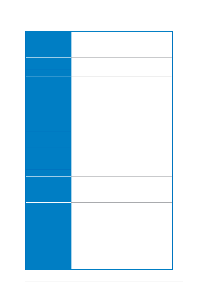
P5QL PRO specications summary
CPU LGA775 socket for Intel® Core™2 Extreme /
Core™2 Quad / Core™2 Duo / Pentium
Celeron
®
Dual-Core / Celeron® processors
®
Dual-Core /
Compatible with Intel® 05B/05A/06 processors
Supports Intel® next-generation 45nm multi-core CPU
Chipset Intel® P43 / ICH10 with Intel® Fast Memory Access
Technology
System Bus 1600(O.C.)*/1333/1066/800 MHz
Memory Dual-channel memory architecture
- 4 x 240-pin DIMM sockets support unbuffered
non-ECC DDR2 1066/800/667MHz memory modules
- Supports up to 16GB system memory
* Refer to www.asus.com or this user manual for the
Memory QVL (Qualied Vendors Lists)
** When you install a total memory of 4GB or more,
Windows® 32-bit operation system may only recognize
less than 3GB. Hence, a total installed memory of less
than 3GB is recommended if you are using a Windows
32-bit operation system.
Expansion Slots 1 x PCI Express™ x16 slot
2 x PCI Express x1 slots
3 x PCI slots
Storage Intel ICH10 southbridge supports:
- 6 x Serial ATA 3.0Gb/s ports
Marvell® 88SE6102 PATA controller supports:
- 1 x UltraDMA 133/100/66 for up to 2 PATA devices
LAN PCIe Gigabit LAN controller featuring AI NET2
Audio Realtek® ALC1200 8-channel High-Denition Audio
CODEC
- Supports Jack-detect and Multi-streaming
- Coaxial S/PDIF out ports at back I/O
- ASUS Noise Filter
USB 12 x USB 2.0 ports (6 at mid-board, 6 at back panel)
ASUS Unique Features ASUS Power Saving Solution:
- ASUS EPU-4 Engine
- ASUS AI Nap
ASUS AI Life Features:
- ASUS Express Gate
ASUS Crystal Sound:
- ASUS Noise Filter
ASUS EZ DIY:
- ASUS Q-Connector
- ASUS O.C. Prole
- ASUS CrashFree BIOS 3
- ASUS EZ Flash 2
(continued on the next page)
xi
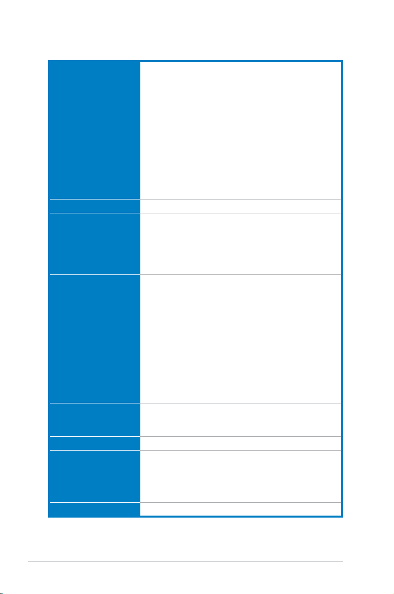
P5QL PRO specications summary
ASUS Exclusive
Overclocking Features
Other Features ASUS MyLogo2
Rear Panel Connectors 1 x PS/2 keyboard port
Internal Connectors 3 x USB connectors support 6 additional USB ports
BIOS Features 8Mb Flash ROM, AMI BIOS, PnP, DMI 2.0, WfM 2.0, SM
Manageability WfM 2.0, DMI 2.0, WOL by PME, WOR by PME, PXE
Support DVD Drivers
Form factor ATX form factor: 12 in x 7.6 in (30.5 cm x 19.3 cm)
Intelligent overclocking tools:
- ASUS AI Booster utility
Precision Tweaker:
- vCore: Adjustable CPU voltage at 0.00625V
increment
- vDIMM: 5-step DRAM voltage control
SFS (Stepless Frequency Selection):
- FSB tuning from 200MHz to 800 MHz at 1MHz
increment
- Memory tuning from 667MHz to 1333MHz for DDR2
- PCI Express frequency tuning from 100MHz to
180MHz at 1MHz increment
Overclocking protection:
- ASUS C.P.R. (CPU Parameter Recall)
1 x PS/2 mouse port
1 x Coaxial S/PDIF Out port
1 x LAN (RJ-45) port
6 x USB 2.0/1.1 ports
8-channel audio I/O ports
1 x Floppy disk drive connector
1 x IDE connector
6 x Serial ATA connectors
1 x CPU / 1 x Chassis / 1 x Power fan connectors
1 x COM connector
1 x S/PDIF Out header
1 x Chassis intrusion connector
Front panel audio connector
1 x CD audio in connector
1 x 24-pin ATX power connector
1 x 4-pin ATX 12V power connector
System panel connector (Q-Connector)
BIOS 2.3, ACPI 2.0a, ASUS EZ Flash 2, ASUS
CrashFree BIOS 3
ASUS PC Probe II
ASUS Update
ASUS AI Suite
Anti-Virus software (OEM version)
*Specications are subject to change without notice.
xii

This chapter describes the motherboard
features and the new technologies
it supports.
Product
1
introduction

Chapter summary
1
1.1 Welcome! ...................................................................................... 1-1
1.2 Package contents .........................................................................
1.3 Special features ............................................................................
1-1
1-2
ASUS P5QL PRO

1.1 Welcome!
Thank you for buying an ASUS® P5QL PRO motherboard!
The motherboard delivers a host of new features and latest technologies, making it
another standout in the long line of ASUS quality motherboards!
Before you start installing the motherboard, and hardware devices on it, check the
items in your package with the list below.
1.2 Package contents
Check your motherboard package for the following items.
Motherboard ASUS P5QL PRO motherboard
Cables 2 x Serial ATA signal cables
1 x Serial ATA power cable
1 x Ultra DMA 133/100/66 cable
1 x Floppy disk drive cable
Accessories 1 x I/O shield
2 in 1 Q-Connector
Application CD ASUS motherboard support DVD
Documentation User guide
If any of the above items is damaged or missing, contact your retailer.
ASUS P5QL PRO 1-1
1.3 Special features
1.3.1 Product highlights
Green ASUS
This motherboard and its packaging comply with the European Union’s Restriction
on the use of Hazardous Substances (RoHS). This is in line with the ASUS vision
of creating environment-friendly and recyclable products/packaging to safeguard
consumers’ health while minimizing the impact on the environment.
Intel® Core™2 Extreme / Core™2 Quad / Core™2 Duo CPU support
This motherboard supports the latest Intel® Core™2 processor in the LGA775
package and Intel® next-generation 45nm multi-core processors. With the new
Intel® Core™ microarchitecture technology and 1333/1066/800 MHz FSB, the
Intel® Core™2 processor is one of the most powerful and energy efcient CPU in
the world. See page 2-6 for details.
Intel® P43 Chipset
The Intel® P43 Express Chipset is designed to support dual-channel DDR2
1066/800/667MHz architecture, 1333/1066/800 FSB (Front Side Bus), PCIe
2.0, and multi-core CPUs. It supports Intel Fast Memory Access technology that
signicantly optimizes the use of available memory bandwidth and reduces the
latency of the memory accesses.
PCI Express 2.0 support
This motherboard supports the latest PCIe 2.0 devices for double speed and
bandwidth which enhances system performance.
FSB 1600 support (O.C.)
ASUS’s exclusive overclocking design now unleashes the ultimate potential of the
Intel® Core™2 processor. With the new Intel 45nm micro-architecture technology
and FSB 1600 (O.C.) / 1333 / 1066 / 800 MHz, this motherboard allows you to
enjoy the latest technology supported by one of the most powerful and energy
efcient CPUs in the world.
1-2 Chapter 1: Product Introduction

Serial ATA 3Gb/s technology
This motherboard supports the next-generation hard drives based on the Serial
ATA (SATA) 3Gb/s storage specication, delivering enhanced scalability and
doubling the bus bandwidth for high-speed data retrieval and saves.
1.3.2 ASUS unique features
ASUS AI Life Features
Express Gate
Taking only 5 seconds to go online from bootup, Express Gate is the one-stop
gateway to instant fun! It’s a unique motherboard built-in OS. You can utilize the
most popular Instant Messengers (IM) like MSN, Skype, Google talk, QQ, and
Yahoo! Messenger to keep in touch with friends, or quickly check on the weather
and e-mails just before leaving your house. What’s more, the user-friendly picture
manager lets you view your pictures without entering Windows at anytime!
• The actual boot time depends on the system conguration.
• ASUS Express Gate supports le uploading from SATA HDDs, ODDs and
USB drives and downloading to USB drives only.
ASUS Power Saving Solution
ASUS Power Saving solution intelligently and automatically provides balanced
computing power and energy consumption.
ASUS EPU-4 Engine
The new ASUS EPU - the world’s rst power saving engine, has been
upgraded to a new four-engine version, which provides total system power
savings by detecting current PC loadings and intelligently moderating power
in real-time. The EPU automatically provides the most appropriate power
usage for the CPU, VGA card, hard drives, and CPU cooler fan - helping
save power and money.
ASUS P5QL PRO 1-3
AI Nap
With AI Nap, users can instantly snooze your PC without terminating the
tasks. The system will continue operating at minimum power and noise when
user is temporarily away. It keeps downloading les or running applications
in quietest state while you are sleeping. Simply click keyboard or mouse, you
can swiftly wake up the system in a few seconds.
ASUS Quiet Thermal Solution
ASUS Quiet Thermal solution makes system more stable and enhances the
overclocking capability.
Fan Xpert
ASUS Fan Xpert intelligently allows users to adjust the CPU fan speed
according to different ambient temperature, which is caused by different
climate conditions in different geographic regions and system loading. Built-in
variety of useful proles offer exible controls of fan speed to achieve a quiet
and cool environment.
ASUS Crystal Sound
This feature can enhance speech-centric applications like Skype, online game,
video conference and recording.
Noise Filter
This feature detects repetitive and stationary noises (non-voice signals) like
computer fans, air conditioners, and other background noises then eliminates
it in the incoming audio stream while recording.
ASUS EZ DIY
ASUS EZ DIY feature collection provides you with easy ways to install computer
components, update the BIOS or back up your favorite settings.
ASUS Q-Connector
ASUS Q-Connector allows you to easily connect or disconnect the chassis
front panel cables to the motherboard. This unique module eliminates the
trouble of plugging in one cable one at a time, making connection quick and
accurate.
1-4 Chapter 1: Product Introduction
ASUS O.C. Prole
The motherboard features the ASUS O.C. Prole that allows users to
conveniently store or load multiple BIOS settings. The BIOS settings can be
stored in the CMOS or a separate le, giving users freedom to share and
distribute their favorite overclocking settings. See page 4-38 for details.
ASUS CrashFree BIOS 3
The ASUS CrashFree BIOS 3 allows users to restore corrupted BIOS data
from a bootable oppy disk, a USB ash disk or the motherboard support
DVD containing the BIOS le. See page 4-8 for details.
ASUS EZ Flash 2
EZ Flash 2 is a user-friendly BIOS update utility. Simply press the predened
hotkey to launch the utility and update the BIOS without entering the OS.
Update your BIOS easily without preparing a bootable diskette or using an
OS-based ash utility. See page 4-5 and 4-37 for details.
ASUS P5QL PRO 1-5
1.3.3 ASUS Stylish features
ASUS MyLogo2™
This feature allows you to convert your favorite photo into a 256-color boot logo for
a more colorful and vivid image on your screen. See page 5-10 for details.
1.3.4 ASUS Intelligent Overclocking features
AI Booster
The ASUS AI Booster allows you to overclock the CPU speed in Windows
environment without the hassle of booting the BIOS. See page 5-24 for details.
Precision Tweaker
This feature allows you to ne tune the CPU/memory voltage and gradually
increase the memory Front Side Bus (FSB) and PCI Express frequency at 1MHz
increment to achieve maximum system performance. See page 4-17 to 4-22 for
details.
C.P.R. (CPU Parameter Recall)
The C.P.R. feature of the motherboard BIOS allows automatic re-setting to the
BIOS default settings in case the system hangs due to overclocking failure. When
the system hangs due to overclocking failure, C.P.R. eliminates the need to open
the system chassis and clear the RTC data. Simply shut down and reboot the
system, and the BIOS automatically restores the CPU default settings for each
parameter.
1-6 Chapter 1: Product Introduction

This chapter lists the hardware setup
procedures that you have to perform
when installing system components. It
includes description of the jumpers and
connectors on the motherboard.
information
Hardware
2

Chapter summary
2
2.1 Before you proceed ..................................................................... 2-1
2.2 Motherboard overview .................................................................
2.3 Central Processing Unit (CPU) ...................................................
2.4 System memory .........................................................................
2.5 Expansion slots ..........................................................................
2.6 Jumpers ......................................................................................
2.7 Connectors .................................................................................
2-2
2-6
2-12
2-18
2-21
2-23
ASUS P5QL PRO
2.1 Before you proceed
P5QL PRO Onboard LED
SB_PWR
ON
Standby
Power
OFF
Powered
Off
P5QL PRO
Take note of the following precautions before you install motherboard components
or change any motherboard settings.
• Unplug the power cord from the wall socket before touching any
component.
• Use a grounded wrist strap or touch a safely grounded object or a metal
object, such as the power supply case, before handling components to
avoid damaging them due to static electricity.
• Hold components by the edges to avoid touching the ICs on them.
• Whenever you uninstall any component, place it on a grounded antistatic
pad or in the bag that came with the component.
• Before you install or remove any component, ensure that the ATX power
supply is switched off or the power cord is detached from the power
supply. Failure to do so may cause severe damage to the motherboard,
peripherals, and/or components.
Onboard LED
The motherboard comes with a standby power LED that lights up to indicate that
the system is ON, in sleep mode, or in soft-off mode. This is a reminder that you
should shut down the system and unplug the power cable before removing or
plugging in any motherboard component. The illustration below shows the location
of the onboard LED.
ASUS P5QL PRO 2-1
P5QL PRO
2.2 Motherboard overview
Before you install the motherboard, study the conguration of your chassis to
ensure that the motherboard ts into it.
Ensure that you unplug the power cord before installing or removing the
motherboard. Failure to do so can cause you physical injury and damage
motherboard components.
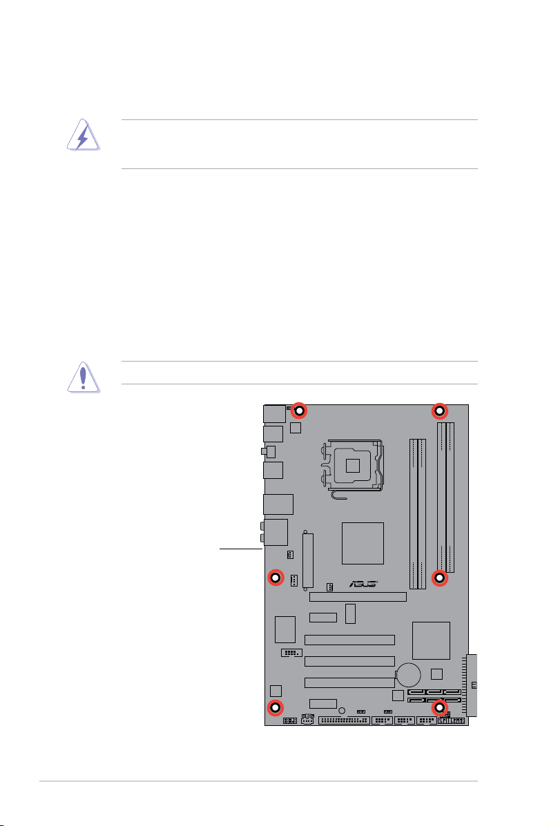
2.2.1 Placement direction
When installing the motherboard, make sure that you place it into the chassis in
the correct orientation. The edge with external ports goes to the rear part of the
chassis as indicated in the image below.
2.2.2 Screw holes
Place six (6) screws into the holes indicated by circles to secure the motherboard
to the chassis.
Do not overtighten the screws! Doing so can damage the motherboard.
Place this side towards
the rear of the chassis
2-2 Chapter 2: Hardware information
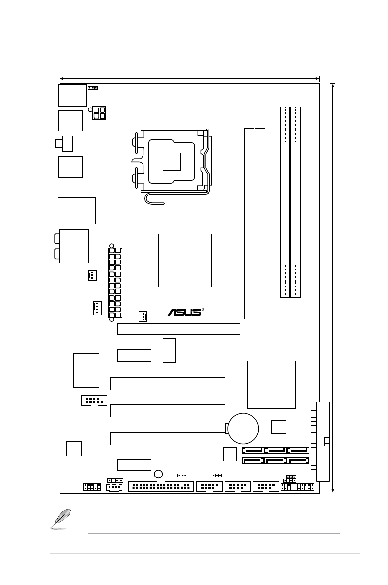
30.5cm (12in)
AUDIO
LAN1_USB12
USB34
USB56
PS/2KBMS
T:Mouse
B:Keyboard
LGA775
DDR2 DIMMB1 (64 bit,240-pin module)
DDR2 DIMMB2 (64 bit,240-pin module)
DDR2 DIMMA1 (64 bit,240-pin module)
DDR2 DIMMA2 (64 bit,240-pin module)
CD
19.3cm (7.6in)
CPU_FAN
Intel
P43
Intel
ICH10
CHASSIS
CLRTC
FLOPPY
PCIEX16
PCI1
PCI2
PCI3
PCIEX1_1
PCIEX1_2
CR2032 3V
Lithium Cell
CMOS Power
4Mb
BIOS
USBPW7-10
USBPW1112
Super I/O
SPDIF_OUT
AAFP
ALC
1200
COM1
PS2_USBPW56
ATX12V
EA
TXPWR
PANEL
SB_PWR
ICS
9LPRS916JGLF
CHA_FAN
PWR_FAN
SPDIF_O1
USB1112 USB78 USB910
Marvell
88SE6102
P5QL PRO
2.2.3 Motherboard layout
ASUS P5QL PRO 2-3
Refer to 2.7 Connectors for more information about rear panel connectors and
internal connectors.
2.2.4 Layout contents
Slots Page
1. DDR2 DIMM slots 2-12
2. PCI slots
3 PCI Express x1 slot
4. PCI Express x16 slots
Jumper Page
1. Clear RTC RAM (3-pin CLRTC) 2-21
2. Keyboard power (3-pin PS2_USBPW56)
3. USB device wake-up (3-pin USBPW1-4, USBPW7-10,
USBPW1112)
Rear panel connectors Page
1. PS/2 mouse port (green) 2-23
2. LAN (RJ-45) port
3. Rear Speaker Out port (black)
4. Center/Subwoofer port (orange)
5. Line In port (light blue)
6. Line Out port (lime)
7. Microphone port (pink)
8. Side Speaker Out port (gray)
9. USB 2.0 ports 1 and 2
10. USB 2.0 ports 3 and 4
11. Coaxial S/PDIF Out port
12. USB 2.0 ports 5 and 6
13. PS/2 keyboard port (purple)
2-20
2-20
2-20
2-22
2-22
2-23
2-23
2-23
2-23
2-23
2-24
2-24
2-24
2-24
2-24
2-24
2-24
2-4 Chapter 2: Hardware information

Internal connectors Page
1. Floppy disk drive connector (34-1 pin FLOPPY) 2-25
2. Digital audio connector (4-1 pin SPDIF_OUT) 2-25
3. IDE connector (40-1 pin PRI_EIDE) 2-26
4. Serial ATA connectors (7-pin SATA1-6) 2-27
5. USB connectors (10-1 pin USB78, USB910, USB1112)
6. Optical drive audio connector (4-pin CD) 2-28
7. CPU, chassis, and power fan connectors (4-pin CPU_FAN,
3-pin CHA_FAN, 3-pin PWR_FAN)
8. Serial port connector (10-1 pin COM1)
9. Chassis intrusion connector (4-1 pin CHASSIS) 2-30
10. Front panel audio connector (10-1 pin AAFP)
11. ATX power connectors (24-pin EATXPWR, 4-pin EATX12V)
12. System panel connector (20-8 pin PANEL)
• System power LED (2-pin PLED)
• Hard disk drive activity LED (2-pin IDE_LED)
• System warning speaker (4-pin SPEAKER)
• ATX power button/soft-off button (2-pin PWRSW)
• Reset button (2-pin RESET)
ASUS Q-connector (system panel) 2-33
2-28
2-29
2-29
2-30
2-31
2-32
ASUS P5QL PRO 2-5

2.3 Central Processing Unit (CPU)
The motherboard comes with a surface mount LGA775 socket designed for the
Intel® Core™2 Extreme / Core™2 Quad / Core™2 Duo / Pentium® Dual-Core /
Celeron® Dual-Core / Celeron® processors.
• Ensure that all power cables are unplugged before installing the CPU.
• Connect the chassis fan cable to the CHA_FAN connector to ensure
system stability.
•
Upon purchase of the motherboard, make sure that the PnP cap is on
the socket and the socket contacts are not bent. Contact your retailer
immediately if the PnP cap is missing, or if you see any damage to the PnP
cap/socket contacts/motherboard components. ASUS will shoulder the cost
of repair only if the damage is shipment/transit-related.
•
Keep the cap after installing the motherboard. ASUS will process Return
Merchandise Authorization (RMA) requests only if the motherboard comes
with the cap on the LGA775 socket.
• The product warranty does not cover damage to the socket contacts
resulting from incorrect CPU installation/removal, or misplacement/loss/
incorrect removal of the PnP cap.
2-6 Chapter 2: Hardware information
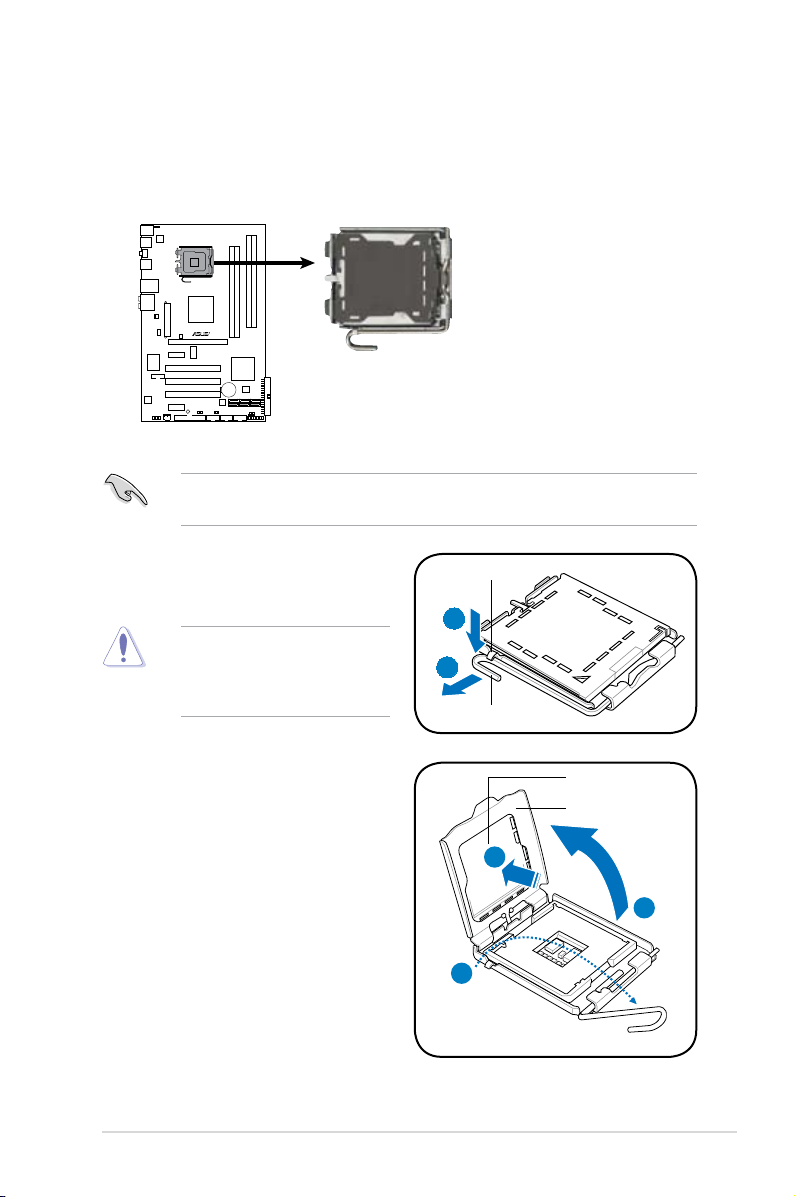
2.3.1 Installing the CPU
P5QL PRO
CPU Socket 775
P5QL PRO
To install a CPU:
1. Locate the CPU socket on the motherboard.
Before installing the CPU, ensure that the socket box is facing towards you and
the load lever is on your left.
2. Press the load lever with your thumb
(A), then move it to the left (B) until it
is released from the retention tab.
To prevent damage to the
socket pins, do not remove
the PnP cap unless you are
installing a CPU.
3. Lift the load lever in the direction of
the arrow to a 135º angle.
4. Lift the load plate with your thumb
and forenger to a 100º angle (4A),
then push the PnP cap from the
load plate window to remove (4B).
Retention tab
A
B
Load lever
PnP cap
Load plate
4B
4A
3
ASUS P5QL PRO 2-7
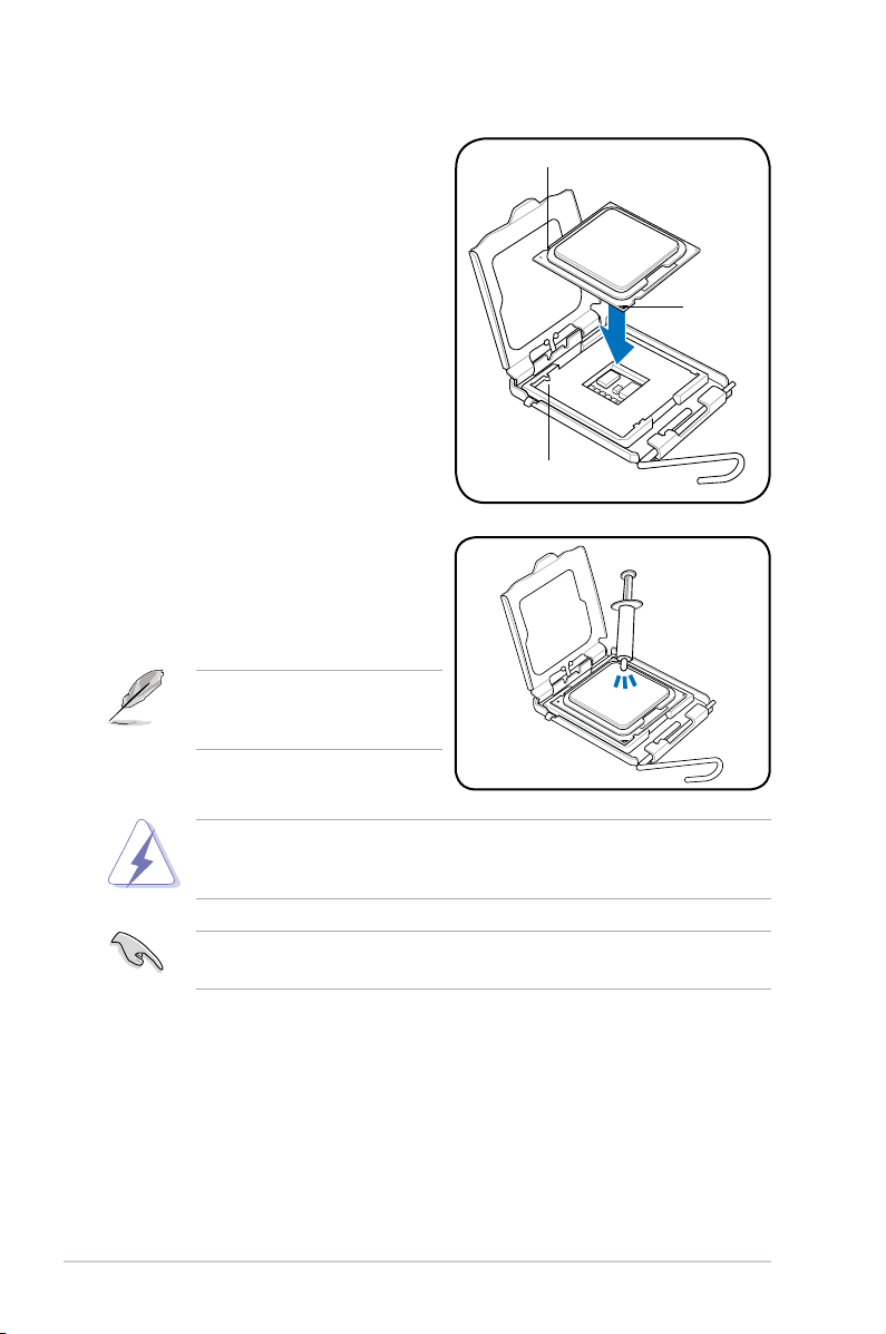
5. Position the CPU over the socket,
ensuring that the gold triangle is on
the bottom-left corner of the socket
then t the socket alignment key
into the CPU notch.
6. Apply several drops of Thermal
Interface Material to the exposed
area of the CPU that the heatsink will
be in contact with, ensuring that it is
spread in an even thin layer.
Some heatsinks come with preapplied thermal paste. If so, skip
this step.
CPU notch
Gold
triangle
mark
Alignment key
DO NOT eat the Thermal Interface Material. If it gets into your eyes or touches
your skin, ensure that you wash it off immediately, and seek professional
medical help.
To prevent contaminating the paste, DO NOT spread the paste with your nger
directly.
2-8 Chapter 2: Hardware information
 Loading...