


P5QD Turbo
Motherboard

E4875
First Edition (V1)
July 2009
Copyright © 2009 ASUSTeK COMPUTER INC. All Rights Reserved.
No part of this manual, including the products and software described in it, may be reproduced, transmitted, transcribed, stored in a retrieval system, or translated into any language in any form or by any means, except documentation kept by the purchaser for backup purposes, without the express written permission of ASUSTeK COMPUTER INC. (“ASUS”).
Product warranty or service will not be extended if: (1) the product is repaired, modified or altered, unless such repair, modification of alteration is authorized in writing byASUS; or (2) the serial number of the product is defaced or missing.
ASUS PROVIDES THIS MANUAL “AS IS” WITHOUT WARRANTY OF ANY KIND, EITHER EXPRESS OR IMPLIED, INCLUDING BUT NOT LIMITED TO THE IMPLIED WARRANTIES OR CONDITIONS OF MERCHANTABILITY OR FITNESS FOR A PARTICULAR PURPOSE. IN NO EVENT SHALL ASUS, ITS DIRECTORS, OFFICERS, EMPLOYEES OR AGENTS BE LIABLE FOR ANY INDIRECT, SPECIAL, INCIDENTAL, OR CONSEQUENTIAL DAMAGES (INCLUDING DAMAGES FOR LOSS OF PROFITS, LOSS OF BUSINESS, LOSS OF USE OR DATA, INTERRUPTION OF BUSINESS AND THE LIKE), EVEN IF ASUS HAS BEEN ADVISED OF THE POSSIBILITY OF SUCH DAMAGES ARISING FROM ANY DEFECT OR ERROR IN THIS MANUAL OR PRODUCT.
SPECIFICATIONS AND INFORMATION CONTAINED IN THIS MANUAL ARE FURNISHED FOR INFORMATIONAL USE ONLY, AND ARE SUBJECT TO CHANGE AT ANY TIME WITHOUT NOTICE, AND SHOULD NOT BE CONSTRUED AS A COMMITMENT BY ASUS. ASUS ASSUMES NO RESPONSIBILITY OR LIABILITY FOR ANY ERRORS OR INACCURACIES THAT MAY APPEAR IN THIS MANUAL, INCLUDING THE PRODUCTS AND SOFTWARE DESCRIBED IN IT.
Products and corporate names appearing in this manual may or may not be registered trademarks or copyrights of their respective companies, and are used only for identification or explanation and to the owners’ benefit, without intent to infringe.
ii

Contents
Contents...................................................................................................................... |
iii |
Notices ....................................................................................................................... |
vii |
Safety information.................................................................................................... |
viii |
About this guide.......................................................................................................... |
ix |
P5QD Turbo specifications summary....................................................................... |
xi |
Chapter 1: |
Product introduction |
|
|
1.1 |
Welcome! |
..................................................................................................... |
1-1 |
1.2 |
Package contents....................................................................................... |
1-1 |
|
1.3 |
Special features.......................................................................................... |
1-2 |
|
|
1.3.1 ........................................................................ |
Product highlights |
1-2 |
|
1.3.2 ................................................................. |
ASUS special features |
1-2 |
|
1.3.3 ........................................ |
ASUS exclusive overclocking features |
1-4 |
Chapter 2: |
Hardware information |
|
|
2.1 |
Before you proceed.................................................................................... |
2-1 |
|
2.2 |
Motherboard overview............................................................................... |
2-2 |
|
|
2.2.1 |
Motherboard layout ...................................................................... |
2-2 |
|
2.2.2 |
Layout contents . .......................................................................... |
2-3 |
|
2.2.3 |
Placement direction ..................................................................... |
2-4 |
|
2.2.4 |
Screw holes ................................................................................. |
2-4 |
2.3 |
Central Processing Unit (CPU).................................................................. |
2-5 |
|
|
2.3.1 |
Installing the CPU ........................................................................ |
2-5 |
|
2.3.2 |
Installing the CPU heatsink and fan ............................................. |
2-8 |
|
2.3.3 |
Uninstalling the CPU heatsink and fan ........................................ |
2-9 |
2.4 |
System memory........................................................................................ |
2-10 |
|
|
2.4.1 |
Overview .................................................................................... |
2-10 |
|
2.4.2 |
Memory configurations . ............................................................. |
2-11 |
|
2.4.3 |
Installing a DIMM ....................................................................... |
2-17 |
|
2.4.4 |
Removing a DIMM ..................................................................... |
2-17 |
2.5 |
Expansion slots........................................................................................ |
2-18 |
|
|
2.5.1 |
Installing an expansion card ...................................................... |
2-18 |
|
2.5.2 |
Configuring an expansion card .................................................. |
2-18 |
|
2.5.3 |
Interrupt assignments ................................................................ |
2-19 |
|
2.5.4 |
PCI slots . ................................................................................... |
2-20 |
|
2.5.5 |
PCI Express x1 slots .................................................................. |
2-20 |
|
2.5.6 |
PCI Express 2.0 x16 slot (blue) ................................................. |
2-20 |
2.6 |
Jumpers |
..................................................................................................... |
2-21 |
2.7 |
Connectors................................................................................................ |
2-24 |
|
|
2.7.1 ............................................................... |
Rear panel connectors |
2-24 |
iii

Contents
|
2.7.2 |
Audio I/O connections................................................................ |
2-25 |
|
2.7.3 |
Internal connectors.................................................................... |
2-28 |
2.8 |
Starting up for the first time.................................................................... |
2-39 |
|
2.9 |
Turning off the computer......................................................................... |
2-39 |
|
Chapter 3: |
BIOS setup |
|
|
3.1 |
Knowing BIOS............................................................................................. |
3-1 |
|
3.2 |
Updating BIOS............................................................................................ |
3-1 |
|
|
3.2.1 |
ASUS Update utility..................................................................... |
3-2 |
|
3.2.2 |
ASUS EZ Flash 2 utility............................................................... |
3-4 |
|
3.2.3 |
ASUS CrashFree BIOS 3 utility................................................... |
3-5 |
3.3 |
BIOS setup program................................................................................... |
3-6 |
|
|
3.3.1 |
BIOS menu screen...................................................................... |
3-6 |
|
3.3.2 |
Menu bar...................................................................................... |
3-6 |
|
3.3.3 |
Navigation keys........................................................................... |
3-7 |
|
3.3.4 |
Menu items.................................................................................. |
3-7 |
|
3.3.5 |
Submenu items............................................................................ |
3-7 |
|
3.3.6 |
Configuration fields...................................................................... |
3-7 |
|
3.3.7 |
Pop-up window............................................................................ |
3-7 |
|
3.3.8 |
Scroll bar...................................................................................... |
3-7 |
|
3.3.9 |
General help................................................................................ |
3-7 |
3.4 |
Main menu................................................................................................... |
3-8 |
|
|
3.4.1 |
SATA1-5; SATA_E1..................................................................... |
3-8 |
|
3.4.2 |
Storage Configuration................................................................ |
3-10 |
|
3.4.3 |
AHCI Configuration.................................................................... |
3-11 |
|
3.4.4 |
System Information.................................................................... |
3-11 |
3.5 |
Ai Tweaker menu...................................................................................... |
3-12 |
|
|
3.5.1 |
Ai Overclock Tuner [Auto].......................................................... |
3-12 |
|
3.5.2 |
CPU Ratio Setting [Auto]........................................................... |
3-13 |
|
3.5.3 |
FSB Frequency [XXX]................................................................ |
3-13 |
|
3.5.4 |
PCIE Frequency [XXX].............................................................. |
3-13 |
|
3.5.5 |
FSB Strap to North Bridge [Auto]............................................... |
3-13 |
|
3.5.6 |
DRAM Frequency [Auto]............................................................ |
3-13 |
|
3.5.7 |
DRAM Timing Control [Auto]...................................................... |
3-13 |
|
3.5.8 |
DRAM Static Read Control [Auto].............................................. |
3-15 |
|
3.5.9 |
DRAM Read Training [Auto]...................................................... |
3-15 |
|
3.5.10 |
MEM. OC Charger [Auto]........................................................... |
3-15 |
|
3.5.11 |
Ai Clock Twister [Auto]............................................................... |
3-15 |
|
3.5.12 |
Ai Transaction Booster [Auto].................................................... |
3-15 |
iv

Contents
|
3.5.13 |
CPU Voltage [Auto].................................................................... |
3-16 |
|
3.5.14 |
CPU GTL Reference [Auto]....................................................... |
3-16 |
|
3.5.15 |
CPU PLL Voltage [Auto]............................................................ |
3-16 |
|
3.5.16 |
FSB Termination Voltage [Auto]................................................. |
3-16 |
|
3.5.17 |
DRAM Voltage [Auto]................................................................. |
3-16 |
|
3.5.18 |
NB Voltage [Auto]...................................................................... |
3-16 |
|
3.5.19 |
SB Voltage [Auto]....................................................................... |
3-17 |
|
3.5.20 |
PCIE SATA Voltage [Auto]......................................................... |
3-17 |
|
3.5.21 |
Load-Line Calibration [Auto]...................................................... |
3-17 |
|
3.5.22 |
CPU Spread Spectrum [Auto].................................................... |
3-17 |
|
3.5.23 |
PCIE Spread Spectrum [Auto]................................................... |
3-17 |
|
3.5.24 |
CPU Clock Skew [Auto]............................................................. |
3-17 |
|
3.5.25 |
NB Clock Skew [Auto]................................................................ |
3-17 |
|
3.5.26 |
CPU Margin Enhancement [Optimized]..................................... |
3-17 |
3.6 |
Advanced menu........................................................................................ |
3-18 |
|
|
3.6.1 |
CPU Configuration..................................................................... |
3-18 |
|
3.6.2 |
Chipset....................................................................................... |
3-20 |
|
3.6.3 |
Onboard Devices Configuration................................................. |
3-21 |
|
3.6.4 |
USB Configuration..................................................................... |
3-22 |
|
3.6.5 |
PCIPnP...................................................................................... |
3-23 |
3.7 |
Power menu.............................................................................................. |
3-24 |
|
|
3.7.1 |
Suspend Mode [Auto]................................................................ |
3-24 |
|
3.7.2 |
Repost Video on S3 Resume [No]............................................. |
3-24 |
|
3.7.3 |
ACPI 2.0 Support [Disabled]...................................................... |
3-24 |
|
3.7.4 |
ACPI APIC Support [Enabled]................................................... |
3-24 |
|
3.7.5 |
APM Configuration..................................................................... |
3-25 |
|
3.7.6 |
Hardware Monitor...................................................................... |
3-26 |
3.8 |
Boot menu................................................................................................. |
3-27 |
|
|
3.8.1 |
Boot Device Priority................................................................... |
3-27 |
|
3.8.2 |
Boot Settings Configuration....................................................... |
3-28 |
|
3.8.3 |
Security...................................................................................... |
3-29 |
3.9 |
Tools menu................................................................................................ |
3-31 |
|
|
3.9.1 |
ASUS EZ Flash 2....................................................................... |
3-31 |
|
3.9.2 |
Drive Xpert Mode Update [Last Setting].................................... |
3-32 |
|
3.9.3 |
Express Gate [Enabled]............................................................. |
3-33 |
|
3.9.4 |
ASUS O.C. Profile..................................................................... |
3-34 |
|
3.9.5 |
AI NET 2.................................................................................... |
3-35 |
3.10 |
Exit menu................................................................................................... |
3-36 |
|

Contents
Chapter 4: |
Software support |
|
|
4.1 |
Installing an operating system.................................................................. |
4-1 |
|
4.2 |
Support DVD information........................................................................... |
4-1 |
|
|
4.2.1 |
Running the support DVD............................................................ |
4-1 |
|
4.2.2 |
Obtaining the software manuals.................................................. |
4-2 |
4.3 |
Software information.................................................................................. |
4-3 |
|
|
4.3.1 |
ASUS PC Probe II....................................................................... |
4-3 |
|
4.3.2 |
ASUS AI Suite.............................................................................. |
4-4 |
|
4.3.3 |
ASUS EPU................................................................................... |
4-5 |
|
4.3.4 |
ASUS Fan Xpert.......................................................................... |
4-6 |
|
4.3.5 |
ASUS TurboV.............................................................................. |
4-7 |
|
4.3.6 |
ASUS Turbo Key.......................................................................... |
4-8 |
|
4.3.7 |
ASUS Drive Xpert........................................................................ |
4-9 |
|
4.3.8 |
ASUS Express Gate.................................................................. |
4-10 |
|
4.3.9 |
Audio configurations.................................................................. |
4-11 |
4.4 |
RAID configurations................................................................................. |
4-12 |
|
|
4.4.1 |
RAID definitions......................................................................... |
4-12 |
|
4.4.2 |
Installing Serial ATA hard disks.................................................. |
4-12 |
|
4.4.3 |
Setting the RAID item in BIOS................................................... |
4-13 |
|
4.4.4 |
Intel® Matrix Storage Manager option ROM utility..................... |
4-13 |
4.5 |
Creating a RAID driver disk..................................................................... |
4-17 |
|
|
4.5.1 |
Creating a RAID driver disk without entering the OS................. |
4-17 |
|
4.5.2 |
Creating a RAID driver disk in Windows®.................................. |
4-17 |
|
4.5.3 |
Using a USB floppy disk drive................................................... |
4-19 |
vi
Notices
Federal Communications Commission Statement
This device complies with Part 15 of the FCC Rules. Operation is subject to the following two conditions:
•This device may not cause harmful interference, and
•This device must accept any interference received including interference that may cause undesired operation.
This equipment has been tested and found to comply with the limits for a Class B digital device, pursuant to Part 15 of the FCC Rules. These limits are designed to provide reasonable protection against harmful interference in a residential installation. This equipment generates, uses and can radiate radio frequency energy and, if not installed and used in accordance with manufacturer’s instructions, may cause harmful interference to radio communications. However, there is no guarantee that interference will not occur in a particular installation. If this equipment does cause harmful interference to radio or
television reception, which can be determined by turning the equipment off and on, the user is encouraged to try to correct the interference by one or more of the following measures:
•Reorient or relocate the receiving antenna.
•Increase the separation between the equipment and receiver.
•Connect the equipment to an outlet on a circuit different from that to which the receiver is connected.
•Consult the dealer or an experienced radio/TV technician for help.
The use of shielded cables for connection of the monitor to the graphics card is required to assure compliance with FCC regulations. Changes or modifications to this unit not expressly approved by the party responsible for compliance could void the user’s authority to operate this equipment.
Canadian Department of Communications Statement
This digital apparatus does not exceed the Class B limits for radio noise emissions from digital apparatus set out in the Radio Interference Regulations of the Canadian Department of Communications.
This class B digital apparatus complies with Canadian ICES-003.
REACH
Complying with the REACH (Registration, Evaluation, Authorisation, and Restriction of Chemicals) regulatory framework, we published the chemical substances in our products at ASUS REACH website at http://green.asus.com/english/REACH.htm.
DO NOT throw the motherboard in municipal waste. This product has been designed to enable proper reuse of parts and recycling. This symbol of the crossed out wheeled bin indicates that the product (electrical and electronic equipment) should not be placed in municipal waste. Check local regulations for disposal of electronic products.
DO NOT throw the mercury-containing button cell battery in municipal waste. This symbol of the crossed out wheeled bin indicates that the battery should not be placed in municipal waste.
vii
Safety information
Electrical safety
•To prevent electrical shock hazard, disconnect the power cable from the electrical outlet before relocating the system.
•When adding or removing devices to or from the system, ensure that the power cables for the devices are unplugged before the signal cables are connected. If possible, disconnect all power cables from the existing system before you add a device.
•Before connecting or removing signal cables from the motherboard, ensure that all power cables are unplugged.
•Seek professional assistance before using an adapter or extension cord. These devices could interrupt the grounding circuit.
•Ensure that your power supply is set to the correct voltage in your area. If you are not sure about the voltage of the electrical outlet you are using, contact your local power company.
•If the power supply is broken, do not try to fix it by yourself. Contact a qualified service technician or your retailer.
•The optical S/PDIF is an optional component (may or may not be included in your motherboard) and is defined as a CLASS 1 LASER PRODUCT.
INVISIBLE LASER RADIATION, AVOID EXPOSURE TO BEAM.
•Never dispose of the battery in fire. It could explode and release harmful substances into the environment.
•Never dispose of the battery with your regular household waste. Take it to a hazardous material collection point.
•Never replace the battery with an incorrect battery type.
•RISK OF EXPLOSION IF BATTERY IS REPLACED BY AN INCORRECT TYPE.
•DISPOSE OF USED BATTERIES ACCORDING TO THE ABOVE BATTERY-RELATED INSTRUCTIONS.
Operation safety
•Before installing the motherboard and adding devices on it, carefully read all the manuals that came with the package.
•Before using the product, ensure all cables are correctly connected and the power cables are not damaged. If you detect any damage, contact your dealer immediately.
•To avoid short circuits, keep paper clips, screws, and staples away from connectors, slots, sockets and circuitry.
•Avoid dust, humidity, and temperature extremes. Do not place the product in any area where it may become wet.
This motherboard should only be used in environments with ambient temperatures between 5°C (41°F) and 40°C (104°F).
•Place the product on a stable surface.
•If you encounter technical problems with the product, contact a qualified service technician or your retailer.
viii

About this guide
This user guide contains the information you need when installing and configuring the motherboard.
How this guide is organized
This guide contains the following parts:
•Chapter 1: Product introduction
This chapter describes the features of the motherboard and the new technology it supports.
•Chapter 2: Hardware information
This chapter lists the hardware setup procedures that you have to perform when installing system components. It includes description of the switches, jumpers, and connectors on the motherboard.
•Chapter 3: BIOS setup
This chapter tells how to change system settings through the BIOS Setup menus. Detailed descriptions of the BIOS parameters are also provided.
•Chapter 4: Software support
This chapter describes the contents of the support DVD that comes with the motherboard package and the software.
Where to find more information
Refer to the following sources for additional information and for product and software updates.
1.ASUS websites
The ASUS website provides updated information on ASUS hardware and software products. Refer to the ASUS contact information.
2.Optional documentation
Your product package may include optional documentation, such as warranty flyers, that may have been added by your dealer. These documents are not part of the standard package.
ix

Conventions used in this guide
To ensure that you perform certain tasks properly, take note of the following symbols used throughout this manual.
DANGER/WARNING: Information to prevent injury to yourself when trying to complete a task.
CAUTION: Information to prevent damage to the components when trying to complete a task.
IMPORTANT: Instructions that you MUST follow to complete a task.
NOTE: Tips and additional information to help you complete a task.
Typography
Bold text |
Indicates a menu or an item to select. |
Italics |
Used to emphasize a word or a phrase. |
<Key> |
Keys enclosed in the less-than and greater-than sign means |
|
that you must press the enclosed key. |
|
Example: <Enter> means that you must press the Enter or |
|
Return key. |
<Key1> + <Key2> + <Key3> |
If you must press two or more keys simultaneously, the key |
|
names are linked with a plus sign (+). |
|
Example: <Ctrl> + <Alt> + <Del> |
Command |
Means that you must type the command exactly as shown, then |
|
supply the required item or value enclosed in brackets. |
|
Example: At the DOS prompt, type the command line: |
|
afudos /iP5QDT.ROM |
P5QD Turbo specifications summary
CPU
Chipset
System bus
Memory
Expansion slots
Storage
LAN
Audio
IEEE 1394
USB
LGA775 socket for Intel® Core™2 Extreme /
Core™2 Quad / Core™2 Duo / Pentium® dual-core / Celeron® dual-core / Celeron® processors
Supports Intel® 45nm multi-core CPUs
Intel® P45 / ICH10R with Intel® Fast Memory Access (FMA) Technology
1600 / 1333 / 1066 / 800 MHz
4 x DIMM, max. 16 GB, DDR2 1300 / 1200 / 1066 / 800 / 667 MHz, non-ECC, un-buffered memory
Dual channel memory architecture
* Refer to www.asus.com or user manual for the Memory QVL
(Qualified Vendors Lists).
** When you install a total memory of 4 GB capacity or more, Windows® 32-bit operating system may only recognize less than 3 GB. We recommend using a maximum of 3 GB system memory if you are using a Windows® 32-bit OS.
1 x PCI Express 2.0 x16 slot
3 x PCI Express x1 slots
2 x PCI slots
Intel® ICH10R Southbridge:
- 5 x SATA 3.0 Gb/s ports
- Intel® Matrix Storage Technology with RAID 0, 1, 5, and 10 support
JMicron® JMB361 SATA and PATA controller:
- 1 x UltraDMA 133 / 100 / 66 for up to 2 PATA devices - 1 x External SATA 3.0 Gb/s port (SATA On-the-Go)
Silicon Image® Sil5723 controller (Drive Xpert technology):
- 2 x SATA 3.0 Gb/s ports
- Supports EZ Backup and Super Speed functions
* Drive Xpert function is available only when the hard disk dirves are set as data drives.
Atheros® L1E Gigabit LAN controller featuring AI NET 2
VIA® VT1708S 8-channel High DefinitionAudio CODEC
- Supports Jack-Detection and Multi-Streaming - Optical S/PDIF Out port at back I/O
- ASUS Noise Filter
VIA® VT6315N controller supports 2 x IEEE 1394a ports
(one at midboard; one at back panel)
12 x USB 2.0/1.1 ports (6 ports at midboard; 6 ports at back panel)
(continued on the next page)
xi

P5QD Turbo specifications summary
ASUS special features
Other features
ASUS exclusive overclocking features
Back panel I/O ports
ASUS Exclusive Features:
- ASUS 8-Phase Power Design
- ASUS Express Gate
ASUS Power Saving Solutions:
- ASUS EPU
ASUS Quiet Thermal Solutions:
- ASUS Fanless Design: Stylish heatsink solution
- ASUS Fan Xpert
ASUS EZ DIY
- ASUS Drive Xpert
- ASUS CrashFree BIOS 3
- ASUS Q-Shield
- ASUS Q-Connector
- ASUS O.C. Profile
- ASUS EZ Flash 2
100% High-quality conductive polymer capacitors
2oz Copper PCB
ASUS MyLogo 2™
Intelligent overclocking tools: |
|
- AI Overclocking (intelligent CPU frequency tuner) |
|
- |
TurboV |
- |
Turbo Key |
Precision Tweaker 2:
- vCore: Adjustable CPU voltage at 0.00625V increment - vDIMM: 64-step DRAM voltage control
- vChipset: 55-step chipset voltage control
- vCPU PLL: 64-step CPU PLL voltage control
- vFSB Termination: 35-step reference voltage control
SFS (Stepless Frequency Selection):
- FSBtuningfrom200MHzupto800MHzat1MHzincrement - PCI Express frequency tuning from 100 MHz to 180 MHz
at 1 MHz increment
Overclocking protection:
- ASUS C.P.R. (CPU Parameter Recall)
1 x PS/2 keyboard port (purple)
1 x PS/2 mouse port (green)
1 x Optical S/PDIF Out port
1 x IEEE 1394a port
1 x External SATA port
1 x LAN (RJ-45) port
6 x USB 2.0/1.1 ports
8-channel Audio I/O ports
(continued on the next page)
xii
P5QD Turbo specifications summary
Internal I/O connectors
BIOS features
Manageability
Support DVD contents
Form factor
3 x USB connectors support additional 6 USB ports
1 x IDE connector
1 x COM connector
5 x SATA connectors (red)
2 x Drive Xpert SATA connectors (orange and white)
1 x CPU Fan connector
2 x Chassis Fan connectors
1 x Power Fan connector
1 x IEEE1394a connector Front panel audio connector 1 x S/PDIF Out header Chassis Intrusion connector CD audio in
24-pin ATX Power connector
8-pin ATX 12V Power connector System Panel (Q-Connector)
8 Mb AMI BIOS, PnP, DMI 2.0, WfM 2.0, SM BIOS 2.5, ACPI 3.0, ASUS EZ Flash 2, ASUS CrashFree BIOS 3
WOL by PME, WOR by PME, WOR by Ring, PXE
Drivers
Express Gate
ASUS PC Probe II
ASUS Update
ASUS AI Suite
Anti-virus software (OEM version)
ATX form factor: 12 in. x 9.2 in. (30.5 cm x 23.4 cm)
*Specifications are subject to change without notice.
xiii

xiv
Chapter 1
Chapter 1: |
Product introduction |
1.1Welcome!
Thank you for buying an ASUS® P5QD Turbo motherboard!
The motherboard delivers a host of new features and latest technologies, making it another standout in the long line of ASUS quality motherboards!
Before you start installing the motherboard, and hardware devices on it, check the items in your package with the list below.
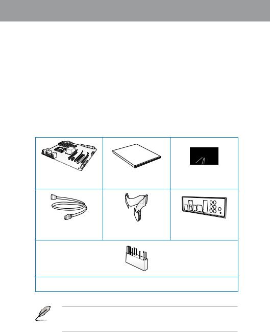
1.2Package contents
Check your motherboard package for the following items.
Chapter 1
Manual
User
ASUS P5QD Turbo |
User guide |
Support DVD |
|
motherboard |
|||
|
|
4 x Serial ATA signal cables |
1 x Ultra DMA 133/ |
1 x ASUS Q-Shield |
|
100/66 cable |
|||
|
|
1 x ASUS Q-Connector kit
• If any of the above items is damaged or missing, contact your retailer.
• The illustrated items above are for reference only.Actual product specifications may vary with different models.
ASUS P5QD Turbo |
1-1 |

1 Chapter
1.3Special features
1.3.1Product highlights
LGA775 Intel® Core™2 Processor Ready
This motherboard supports the latest Intel® Core™2 processors in the LGA775 package. It also supports Intel® 45nm multi-core CPUs. With the new Intel® Core™ microarchitecture and 1600 / 1333 / 1066 / 800 MHz FSB, Intel® Core™2 processor is one of the most powerful and energy efficient CPU in the world.
Intel® P45 Chipset
The Intel® P45 Chipset supports dual-channel DDR2 800/667 MHz memory architecture, 1333/1066/800 MHz FSB (Front Side Bus), PCIe 2.0, and multi-core CPUs. It especially includes Intel® Fast MemoryAccess technology that significantly optimizes the use of available memory bandwidth and reduces the latency of the memory accesses.
Dual-Channel DDR2 1300 support
The motherboard supports DDR2 memory that features data transfer rates of 1300 /1200
/ 1066 / 800 / 667 MHz to meet the higher bandwidth requirements of the latest operation system, 3D graphics, multimedia, and Internet applications. The dual-channel DDR2 architecture doubles the bandwidth of your system memory to boost system performance, eliminating bottlenecks with peak bandwidths of up to 20.8 GB/s.
100% high-quality conductive polymer capacitors
This motherboard uses all high-quality conductive polymer capacitors for durability, improved lifespan, and enhanced thermal capacity.
Green ASUS
This motherboard and its packaging comply with the European Union’s Restriction on the use of Hazardous Substances (RoHS). This is in line with theASUS vision of creating environment-friendly and recyclable products/packaging to safeguard consumers’ health while minimizing the impact on the environment.
1.3.2ASUS special features
ASUS 8-Phase Power Design
With power efficiency so important to operating temperatures,ASUS 8-Phase VRM design leads the industry with its 96% power efficiency. High quality power components such as low
RDS (on) MOSFETs for minimum switching loss & lower temperatures, Ferrite core chokes with lower hysteresis loss, and high quality Japanese-made conductive polymer capacitors all add up to ensure longer component life and lower power loss—creating more energy efficiency.
1-2 |
Chapter 1: Product Introduction |

Express Gate
Taking only 5 seconds to bootup, Express Gate is the one-stop gateway to instant fun! It’s a unique motherboard built-in OS. You can utilize the most popular Instant Messengers (IM) like MSN, Skype, Google talk, QQ, and Yahoo! Messenger to keep in touch with friends,
or quickly check on the weather and e-mails just before leaving your house. What’s more, the user-friendly picture manager lets you view your pictures without entering Windows at anytime!
The actual boot time is subject to hardware configurations and product models.
ASUS Power Saving Solution
ASUS Power Saving solution intelligently and automatically provides balanced computing power and energy consumption.
ASUS EPU
The ASUS EPU (Energy Processing Unit) provides total system power management by detecting current PC loadings and intelligently moderating power usage for critical PC components in real-time–helping save power and money!
ASUS Quiet Thermal Solutions
ASUS Quiet Thermal solutions make the system more stable and enhance the overclocking capability.
Fanless Design—Unique stylish heatsink
The brand new 2-color heatsink features 0-dB thermal solution that offers users a noiseless PC environment. The Paten Pending 2-color design within the beautifully curved fins upgrades the visual enjoyment for the motherboard users, and also effectively cools down hot airflows generated by the north bridge chipset. Combined with usability and aesthetics, the ASUS Patent 2-color Wing heatsink will give users an extremely silent and cooling experience with the elegant appearance!
Fan Xpert
ASUS Fan Xpert intelligently allows you to adjust both the CPU and chassis fan speeds according to different ambient temperatures caused by different climate conditions
in different geographic regions and your PC’s loading. The built-in variety of useful profiles offer flexible controls of fan speed to achieve a quiet and cool environment.
ASUS EZ DIY
ASUS EZ DIY feature collection provides you with easy ways to install computer components, update the BIOS, or back up your favorite settings.
ASUS Drive Xpert
Without drivers or BIOS setups, the ASUS exclusive Drive Xpert is ideal for anyone who needs to secure data on their hard drives or enhance hard drive performances without the hassles of complicated configurations. With Drive Xpert’s user-friendly graphical user interface, you can easily arrange hard drive backups or enhance their hard drive transfer rates - ensuring that data is looked after every moment, every day.
Chapter 1
ASUS P5QD Turbo |
1-3 |

1 Chapter
ASUS CrashFree BIOS 3
ASUS CrashFree BIOS 3 allows you to restore corrupted BIOS data from a USB flash disk containing the BIOS file. This protection eliminates the need to buy a replacement
ROM chip.
ASUS Q-Shield
ASUS Q-Shield’s special design makes it convenient and easy to install on your motherboard. With better electric conductivity, it ideally protects your motherboard against static electricity and shields it against Electronic Magnetic Interference (EMI).
ASUS Q-Connector
ASUS Q-Connector allows you to easily connect or disconnect the chassis front panel cables to the motherboard. This unique module eliminates the trouble of connecting the system panel cables one at a time and avoiding wrong cable connections.
ASUS EZ Flash 2
ASUS EZ Flash 2 is a user-friendly utility that allows you to update the BIOS without using a bootable floppy disk or an OS-based utility.
ASUS O.C. Profile
The motherboard features theASUS O.C. Profile that allows you to conveniently store or load multiple BIOS settings. The BIOS settings can be stored in the CMOS or a separate file, giving you the freedom to share and distribute your favorite settings.
1.3.3ASUS exclusive overclocking features
TurboV
Feel the adrenaline rush of real-time OC—now a reality with the ASUS TurboV. This easy OC tool allows you to overclock without exiting or rebooting the OS; and its user-friendly interface makes overclock with just a few clicks away. Moreover, theASUS OC profiles in TurboV provides the best O.C. settings in different scenarios.
Turbo Key
ASUS Turbo Key allows you to turn the PC power button into a physical overclocking button. After the easy setup, Turbo Key can boost performances without interrupting ongoing work or games, simply through pressing the button
Precision Tweaker 2
Allows you to adjust the CPU voltage in 0.00625v steps and NB/DRAM voltage in 0.02v steps to fine-tune voltage to achieve the most precise setting for the ultimate overclocking configuration.
C.P.R. (CPU Parameter Recall)
The BIOS C.P.R. feature automatically restores the CPU default settings when the system hangs due to overclocking failure. C.P.R. eliminates the need to open the system chassis and clear the RTC data. Simply shut down and reboot the system, and the BIOS automatically restores the CPU parameters to their default settings.
1-4 |
Chapter 1: Product Introduction |
Chapter 2
Chapter 2: |
Hardware information |
2.1Before you proceed
Take note of the following precautions before you install motherboard components or change any motherboard settings.
•Unplug the power cord from the wall socket before touching any component.
• Before handling components, use a grounded wrist strap or touch a safely grounded object or a metal object, such as the power supply case, to avoid damaging them due to static electricity.
•Hold components by the edges to avoid touching the ICs on them.
•Whenever you uninstall any component, place it on a grounded antistatic pad or in the bag that came with the component.
•Before you install or remove any component, ensure that the ATX power supply is switched off or the power cord is detached from the power supply. Failure to do so may cause severe damage to the motherboard, peripherals, or components.
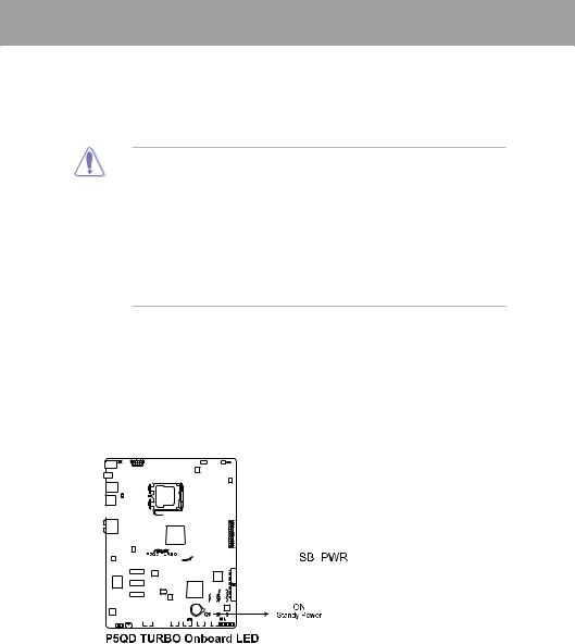
Onboard LED
The motherboard comes with a standby power LED. The green LED lights up to indicate that the system is ON, in sleep mode, or in soft off mode. This is a reminder that you should shut down the system and unplug the power cable before removing or plugging in any motherboard component. The illustration below shows the location of the onboard LED.
Chapter 2
|
|
|
|
|
|
|
|
|
|
|
|
|
|
|
|
|
|
|
|
|
|
|
|
|
|
|
|
|
|
|
|
|
|
|
|
|
|
|
|
|
|
|
|
|
|
|
|
|
|
|
|
|
|
|
|
|
|
|
|
|
|
|
|
|
|
|
|
|
|
|
|
|
|
|
|
|
|
|
|
|
|
|
|
|
|
|
|
|
|
|
|
|
|
|
|
|
|
|
|
|
|
|
|
|
|
|
|
|
|
|
|
|
|
|
|
|
|
|
|
|
|
|
|
|
|
|
|
|
|
|
|
|
|
|
|
|
|
|
|
|
|
|
|
|
|
|
|
|
|
|
|
|
|
|
|
|
|
|
|
|
|
|
|
|
|
|
|
|
|
|
|
|
|
|
|
|
|
|
|
|
|
|
|
|
|
|
|
|
|
|
|
|
|
|
|
|
|
|
|
|
|
|
|
|
|
|
|
|
|
|
|
|
|
|
|
|
|
|
|
|
|
|
|
|
|
|
|
|
|
|
|
|
|
|
|
|
|
|
|
|
|
|
|
|
|
|
|
|
|
|
|
|
|
|
|
|
|
|
|
|
|
|
|
|
|
|
|
|
|
|
|
|
|
|
|
|
|
|
|
|
|
|
|
|
|
|
|
|
|
|
|
|
|
|
|
|
|
|
|
|
|
|
|
|
|
|
|
|
|
|
|
|
|
|
|
|
|
|
|
|
|
|
|
|
|
|
|
|
|
|
|
|
|
|
|
|
|
|
|
|
|
|
|
|
|
|
|
|
|
|
|
|
|
|
|
|
|
|
|
|
|
|
|
|
|
|
|
|
|
|
|
|
|
|
|
|
|
|
|
|
|
|
|
|
|
|
|
|
|
|
|
|
|
|
|
|
|
|
|
|
|
|
|
|
|
|
|
|
|
|
|
|
|
|
|
|
|
|
|
|
|
|
|
|
|
|
|
|
|
|
|
|
|
|
|
|
|
|
|
|
|
|
|
|
|
|
|
|
|
|
|
|
|
|
|
|
|
|
|
|
|
|
|
|
|
|
|
|
|
|
|
|
|
|
|
|
|
|
|
|
|
|
|
|
|
|
|
|
|
|
|
|
|
|
|
|
|
|
|
|
|
|
|
|
|
|
|
|
|
|
|
|
|
|
|
|
|
|
|
|
|
|
|
|
|
|
|
|
|
|
|
|
|
|
|
|
|
|
|
|
|
|
|
|
|
|
|
|
|
|
|
|
|
|
|
|
|
|
|
|
|
|
|
|
|
|
|
|
|
|
|
|
|
|
|
|
|
|
|
|
|
|
|
|
|
|
|
|
|
|
|
|
|
|
|
|
|
|
|
|
|
|
|
|
|
|
|
|
|
|
|
|
|
|
|
|
|
|
|
|
|
|
|
|
|
|
|
|
|
|
|
|
|
|
|
|
|
|
|
|
|
|
|
|
|
|
|
|
|
|
|
|
|
|
|
|
|
|
|
|
|
|
|
|
|
|
|
|
|
|
|
|
|
|
|
|
|
|
|
|
|
|
|
|
|
|
|
|
|
|
|
|
|
|
|
|
|
|
|
|
|
|
|
|
|
|
|
|
|
|
|
|
|
|
|
|
|
|
|
|
|
|
|
|
|
|
|
|
|
|
|
|
|
|
|
|
|
|
|
|
|
|
|
|
|
|
|
|
|
|
|
|
|
|
|
|
|
|
|
|
|
|
|
|
|
|
|
|
|
|
|
|
|
|
|
|
|
|
|
|
|
|
|
|
|
|
|
|
|
|
|
|
|
|
|
|
|
|
|
|
|
|
|
|
|
|
|
|
|
|
|
|
|
|
|
|
|
|
|
|
|
|
|
|
|
|
|
|
|
|
|
|
|
|
|
|
|
|
|
|
|
|
|
|
|
|
|
|
|
|
|
|
|
|
|
|
|
|
|
|
|
|
|
|
|
|
|
|
|
|
|
|
|
|
|
|
|
|
|
|
|
|
|
|
|
|
|
|
|
|
|
|
|
|
|
|
|
|
|
|
|
|
|
|
|
|
|
|
|
|
|
|
|
|
|
|
|
|
|
ASUS P5QD Turbo |
2-1 |
||||||||||||||||||||||||||||||||||||||

2.2Motherboard overview
2.2.1Motherboard layout
2 Chapter
Refer to 2.7 Connectors for more information about rear panel connectors and internal connectors.
2-2 |
Chapter 2: Hardware information |
2.2.2Layout contents
Connectors/Jumpers/Slots |
Page |
|
1. |
Keyboard/mouse power (3-pin PS2_USBPW56) |
2-24 |
2. |
USB device wake-up (3-pin USBPW1-4, USBPW7-10, USBPW1112) |
2-24 |
3. |
ATX power connectors (24-pin EATXPWR, 8-pin EATX12V) |
2-35 |
4. |
LGA775 CPU socket |
2-5 |
5. |
DDR2 DIMM slots |
2-10 |
6. |
CPU, chassis, and power fan connectors |
2-33 |
|
(4-pin CPU_FAN, 3-pin CHA_FAN1–2, 3-pin PWR_FAN) |
|
7. |
CPU overvoltage setting (3-pin OV_CPU) |
2-22 |
8. |
IDE connector (40-1 pin PRI_EIDE) |
2-25 |
9. |
ICH10R Serial ATA connectors (7-pin SATA1–5 [Red]) |
2-29 |
10. |
Standby power LED (SB_PWR) |
2-1 |
11. |
Silicon Image® Sil5723 Serial ATA RAID connectors |
2-30 |
|
(7-pin SATA_E1 [orange, port 0], 7-pin SATA_E2 [white, port 1]) |
|
12. |
Clear RTC RAM (3-pin CLRTC) |
2-21 |
13. |
System panel connector (20-8 pin PANEL) |
2-37 |
14. |
Chassis intrusion connector (4-1 pin CHASSIS) |
2-34 |
15. |
USB connectors (10-1 pin USB78, USB910, USB1112) |
2-31 |
|
|
|
16. |
IEEE 1394a port connector (10-1 pin IE1394_2) |
2-32 |
|
|
|
17. |
Serial port connector (10-1 pin COM1) |
2-32 |
18. |
Optical drive audio connector (4-pin CD) |
2-31 |
19. |
Front panel audio connector (10-1 pin AAFP) |
2-36 |
20. |
Digital audio connector (4-1 pin SPDIF_OUT) |
2-34 |
Chapter 2
ASUS P5QD Turbo |
2-3 |
2 Chapter
2.2.3Placement direction
When installing the motherboard, ensure that you place it into the chassis in the correct orientation. The edge with external ports goes to the rear part of the chassis as indicated in the image below.
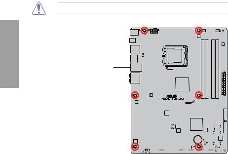
2.2.4Screw holes
Place six screws into the holes indicated by circles to secure the motherboard to the chassis.
DO NOT overtighten the screws! Doing so can damage the motherboard.
Place this side towards  the rear of the chassis
|
|
|
|
|
|
|
|
|
|
|
|
|
|
|
|
|
|
|
|
|
|
|
|
|
|
|
|
|
|
|
|
|
|
|
|
|
|
|
|
|
|
|
|
|
|
|
|
|
|
|
|
|
|
|
|
|
|
|
|
|
|
|
|
|
|
|
|
|
|
|
|
|
|
|
|
|
|
|
|
|
|
|
|
|
|
|
|
|
|
|
|
|
|
|
|
|
|
|
|
|
|
|
|
|
|
|
|
|
|
|
|
|
|
|
|
|
|
|
|
|
|
|
|
|
|
|
|
|
|
|
|
|
|
|
|
|
|
|
|
|
|
|
|
|
|
|
|
|
|
|
|
|
|
|
|
|
|
|
|
|
|
|
|
|
|
|
|
|
|
|
|
|
|
|
|
|
|
|
|
|
|
|
|
|
|
|
|
|
|
|
|
|
|
|
|
|
|
|
|
|
|
|
|
|
|
|
|
|
|
|
|
|
|
|
|
|
|
|
|
|
|
|
|
|
|
|
|
|
|
|
|
|
|
|
|
|
|
|
|
|
|
|
|
|
|
|
|
|
|
|
|
|
|
|
|
|
|
|
|
|
|
|
|
|
|
|
|
|
|
|
|
|
|
|
|
|
|
|
|
|
|
|
|
|
|
|
|
|
|
|
|
|
|
|
|
|
|
|
|
|
|
|
|
|
|
|
|
|
|
|
|
|
|
|
|
|
|
|
|
|
|
|
|
|
|
|
|
|
|
|
|
|
|
|
|
|
|
|
|
|
|
|
|
|
|
|
|
|
|
|
|
|
|
|
|
|
|
|
|
|
|
|
|
|
|
|
|
|
|
|
|
|
|
|
|
|
|
|
|
|
|
|
|
|
|
|
|
|
|
|
|
|
|
|
|
|
|
|
|
|
|
|
|
|
|
|
|
|
|
|
|
|
|
|
|
|
|
|
|
|
|
|
|
|
|
|
|
|
|
|
|
|
|
|
|
|
|
|
|
2-4 |
|
|
|
|
|
|
Chapter 2: Hardware information |
||||||||||||||
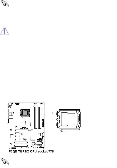
2.3Central Processing Unit (CPU)
The motherboard comes with a surface mount LGA775 socket designed for the Intel® Core™2 Extreme / Core™2 Quad / Core™2 Duo / Pentium® Dual-Core / Celeron® Dual-Core / Celeron® processors.
|
• |
Ensure that all power cables are unplugged before installing the CPU. |
|
|
|
• |
If installing a dual-core CPU, connect the chassis fan cable to the CHA_FAN1 |
|
|
|
|
connector to ensure system stability. |
|
|
|
• |
Due to the chipset limitation, we recommend that you use FSB 800MHz CPU or |
|
|
|
|
above. |
|
|
|
|
|
|
|
|
|
|
|
|
|
• |
Upon purchase of the motherboard, ensure that the PnP cap is on the socket and |
|
|
|
|
the socket contacts are not bent. Contact your retailer immediately if the PnP cap |
|
|
|
|
is missing, or if you see any damage to the PnP cap/socket contacts/motherboard |
|
|
|
|
components. ASUS will shoulder the cost of repair only if the damage is shipment/ |
|
|
|
|
transit-related. |
|
|
|
• |
Keep the cap after installing the motherboard. ASUS will process Return Merchandise |
2 |
|
|
|
Authorization (RMA) requests only if the motherboard comes with the cap on the |
Chapter |
|
|
|
LGA775 socket. |
||
|
|
|
||
|
• |
The product warranty does not cover damage to the socket contacts resulting from |
|
|
|
|
incorrect CPU installation/removal, or misplacement/loss/incorrect removal of the PnP |
|
|
|
|
cap. |
|
|
|
|
|
|
|
|
|
|
|
|
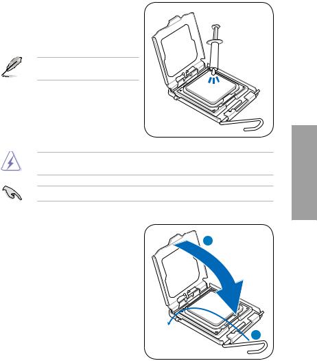
2.3.1 |
Installing the CPU |
|
||
To install a CPU:
1.Locate the CPU socket on the motherboard.
Before installing the CPU, ensure that the cam box is facing towards you and the load lever is on your left.
ASUS P5QD Turbo |
2-5 |
2 Chapter
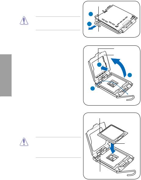
2.Press the load lever with your thumb (A), then move it to the left (B) until it is released from the retention tab.
To prevent damage to the socket pins, do not remove the PnP cap unless you are installing a CPU.
Retention tab A 

B
Load lever
3.Lift the load lever in the direction of the arrow to a 135º angle.
4.Lift the load plate with your thumb and forefinger to a 100º angle (4A), then push the PnP cap from the load plate window to remove (4B).
PnP cap
Load plate
4B
4A
3
5.Position the CPU over the socket, ensuring that the gold triangle is on the bottom left corner of the socket, and then fit the socket alignment key into the CPU notch.
The CPU fits in only one correct orientation. DO NOT force the CPU into the socket to prevent bending the connectors on the socket and damaging the CPU!
CPU notch
Alignment key
Gold triangle mark
2-6 |
Chapter 2: Hardware information |
6.Apply some Thermal Interface Material to the exposed area of the CPU that the heatsink will be in contact with, ensuring that it is spread in an even thin layer.
Some heatsinks come with pre-applied thermal paste. If so, skip this step.
The Thermal Interface Material is toxic and inedible. DO NOT eat it. If it gets into your eyes or touches your skin, wash it off immediately, and seek professional medical help.
To prevent contaminating the paste, DO NOT spread the paste with your finger directly.
7. Close the load plate (A), then push the load lever (B) until it snaps into the
retention tab. |
A |
|
B
Chapter 2
ASUS P5QD Turbo |
2-7 |
2 Chapter
2.3.2Installing the CPU heatsink and fan
The Intel® LGA775 processor requires a specially designed heatsink and fan assembly to ensure optimum thermal condition and performance.
• When you buy a boxed Intel® processor, the package includes the CPU fan and heatsink assembly. If you buy a CPU separately, ensure that you use only Intel® certified multi directional heatsink and fan.
•Your Intel® LGA775 heatsink and fan assembly comes in a push-pin design and requires no tool to install.
Ensure that you have installed the motherboard to the chassis before you install the CPU fan and heatsink assembly.
If you purchased a separate CPU heatsink and fan assembly, ensure that the Thermal Interface Material is properly applied to the CPU heatsink or CPU before you install the heatsink and fan assembly.
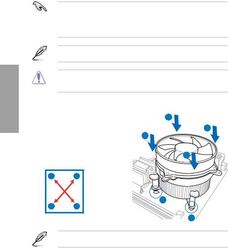
To install the CPU heatsink and fan: |
A |
|||
1. |
Place the heatsink on top of the installed |
|||
B |
||||
|
CPU, ensuring that the four fasteners |
|||
|
B |
|||
|
match the holes on the motherboard. |
|||
2. |
Push down two fasteners at a time in |
|
||
|
a diagonal sequence to secure the |
A |
||
|
heatsink and fan assembly in place. |
|||
|
|
|||
|
A |
B |
|
|
|
B |
A |
1 |
|
|
|
|||
|
|
|
1 |
|
Orient the heatsink and fan assembly such that the CPU fan cable is closest to the CPU fan connector.
2-8 |
Chapter 2: Hardware information |
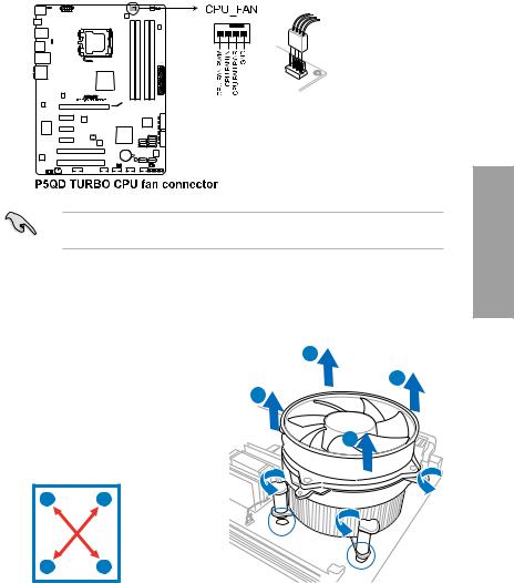
3.Connect the CPU fan cable to the connector on the motherboard labeled CPU_FAN.
DO NOT forget to connect the CPU fan connector! Hardware monitoring errors can occur if you fail to plug this connector.
2.3.3Uninstalling the CPU heatsink and fan
To uninstall the CPU heatsink and fan:
1. |
Disconnect the CPU fan cable from the |
A |
|
|
|||
|
connector on the motherboard. |
B |
|
2. |
Rotate each fastener counterclockwise. |
B |
|
3. |
Pull up two fasteners at a time in a |
|
|
|
diagonal sequence to disengage the |
A |
|
|
heatsink and fan assembly from the |
||
|
motherboard. |
|
|
|
A |
B |
|
BA
4.Carefully remove the heatsink and fan assembly from the motherboard.
Chapter 2
ASUS P5QD Turbo |
2-9 |
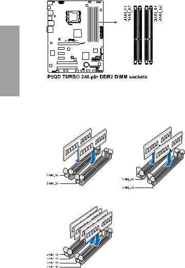
2.4System memory
2.4.1Overview
The motherboard comes with four Double Data Rate 2 (DDR2) Dual Inline Memory Modules (DIMM) sockets.
A DDR2 module has the same physical dimensions as a DDR DIMM but has a 240-pin footprint compared to the 184-pin DDR DIMM. DDR2 DIMMs are notched differently to prevent installation on a DDR DIMM socket.
The figure illustrates the location of the DDR2 DIMM sockets:
2 Chapter
Recommended memory configurations
One DIMM:
You may install one memory module in any slot as a single-channel operation.
Two DIMMs (dual-channel operation):
Four DIMMs (dual-channel operation):
2-10 |
Chapter 2: Hardware information |

2.4.2Memory configurations
You may install 512MB, 1GB, 2GB and 4GB unbuffered ECC and non ECC DDR2 DIMMs into the DIMM sockets.
• You may install varying memory sizes in ChannelAand Channel B. The system maps the total size of the lower-sized channel for the dual-channel configuration.Any excess memory from the higher-sized channel is then mapped for single-channel operation.
•We recommend that you install the memory modules from the yellow slots for better overclocking capability.
•Always install DIMMs with the same CAS latency. For optimum compatibility, it is recommended that you obtain memory modules from the same vendor.
•Due to the memory address limitation on 32-bit Windows OS, when you install 4GB or more memory on the motherboard, the actual usable memory for the OS can be about 3GB or less. For effective use of memory, we recommend that you do any of the following:
-Use a maximum of 3GB system memory if you are using a 32-bit Windows OS.
-Install a 64-bit Windows OS when you want to install 4GB or more on the motherboard.
•This motherboard does not support DIMMs made up of 256 megabit (Mb) chips or less.
• The default memory operation frequency is dependent on its Serial Presence Detect (SPD), which is the standard way of accessing information from a memory module. Under the default state, some memory modules for overclocking may operate at a lower frequency than the vendor-marked value. To operate at the vendor-marked or at a higher frequency, see section 3.5 Ai Tweaker menu for manual memory frequency adjustment.
•For system stability, use a more efficient memory cooling system to support a full memory load (4 DIMMs) or overclocking condition.
Chapter 2
ASUS P5QD Turbo |
2-11 |

2 Chapter
P5QD Turbo Motherboard Qualified Vendors Lists (QVL) DDR2-1300 MHz capability
|
|
|
|
Chip |
|
Timing |
|
DIMM socket |
|||
Vendor |
Part No. |
Size |
SS/DS |
Chip NO. |
Voltage |
support |
|||||
Brand |
Dimm (Bios) |
(Optional) |
|||||||||
|
|
|
|
|
|
|
|
A* |
B* |
C* |
|
Team |
TXDD1024M1300HC6 |
1024MB |
DS |
N/A |
Heat-Sink Package |
6-6-6-18 |
2.35-2.45 |
V |
|
|
|
|
|
|
|
|
|
|
|
|
|
|
|
P5QD Turbo Motherboard Qualified Vendors Lists (QVL) DDR2-1200 MHz capability
|
|
|
SS/ |
Chip |
|
Timing Dimm |
|
DIMM socket |
||
Vendor |
Part No. |
Size |
Chip NO. |
Voltage |
support |
|||||
DS |
Brand |
(Bios) |
(Optional) |
|||||||
|
|
|
|
|
|
|
|
A* |
B* |
C* |
KINGSTON |
KHX9600D2K2/2G |
2048MB(Kit of 2) |
DS |
N/A |
Heat-Sink Package |
|
2.3-2.35 |
V |
|
|
|
|
|
|
|
|
|
|
|
|
|
P5QD Turbo Motherboard Qualified Vendors Lists (QVL) DDR2-1066 MHz capability
Vendor |
Part No. |
Size |
SS/ |
Chip |
Chip NO. |
Timing Dimm |
Voltage |
DIMM socket |
|
|
|
support (Optional) |
|||||||||||
|
|
|
DS |
Brand |
|
(Bios) |
|
|
|
|
|
|
|
|
|
|
A* |
B* |
C* |
|
|||
|
|
|
|
|
|
|
|
||||
Apacer |
BoxP/N:CH.02GAF.C0KK2 |
2048MB(Kit of 2) |
DS |
N/A |
Heat-Sink Package |
5-5-5-15 |
|
V |
V |
V |
|
(78.0AG9S.9KF) |
|
||||||||||
|
|
|
|
|
|
|
|
|
|
|
|
Apacer |
BoxP/N:CH.04GAF.F0KK2 |
4096MB(Kit of 2) |
DS |
N/A |
Heat-Sink Package |
5-5-5-15 |
|
V |
V |
V |
|
(78.AAGAL.9KF) |
|
||||||||||
|
|
|
|
|
|
|
|
|
|
|
|
CORSAIR |
BoxP/N:TWIN2X4096-8500C5DF |
4096MB(Kit of 2) |
DS |
N/A |
Heat-Sink Package |
5-5-5-15 |
2.1 |
V |
V |
V |
|
|
(CM2X2048-8500C5D)(EPP) |
|
|
|
|
|
|
|
|
|
|
Crucial |
BL12864AA106A.8FE5 (EPP) |
1024MB |
SS |
N/A |
Heat-Sink Package |
5-5-5-15 |
2.0 |
V |
V |
V |
|
Crucial |
BL12864AA1065.16FD5 (EPP) |
1024MB |
DS |
N/A |
Heat-Sink Package |
5 |
|
V |
V |
V |
|
G.SKILL |
F2-8500CL5S-1GBPK |
1024MB |
DS |
N/A |
Heat-Sink Package |
5-5-5-15 |
2.0-2.1 |
V |
V |
V |
|
G.SKILL |
F2-8500CL5D-2GBPK |
2048MB(Kit of 2) |
DS |
N/A |
Heat-Sink Package |
5-5-5-15 |
2.0-2.1 |
V |
V |
V |
|
G.SKILL |
F2-8500CL5D-4GBPK |
4096MB(Kit of 2) |
DS |
N/A |
Heat-Sink Package |
5-5-5-15 |
2.0-2.1 |
V |
V |
|
|
GEIL |
GB22GB8500C5DC |
2048MB(Kit of 2) |
SS |
GEIL |
GL2L128M88BA25AB |
5-5-5-15 |
2.2-2.4 |
V |
V |
V |
|
GEIL |
GE22GB1066C5DC |
2048MB(Kit of 2) |
SS |
N/A |
Heat-Sink Package |
5-5-5-15 |
2.2-2.4 |
V |
V |
V |
|
GEIL |
GE24GB1066C5QC |
4096MB(Kitof4) |
SS |
N/A |
Heat-Sink Package |
5-5-5-15 |
2.2-2.4 |
V |
V |
V |
|
GEIL |
GB24GB8500C5DC |
4096MB(Kit of 2) |
DS |
GEIL |
GL2L128M88BA25AB |
5-5-5-15 |
2.2-2.4 |
V |
V |
V |
|
GEIL |
GE24GB1066C5DC |
4096MB(Kit of 2) |
DS |
N/A |
Heat-Sink Package |
5-5-5-15 |
2.2-2.4 |
V |
V |
V |
|
GEIL |
GX24GB8500C5UDC |
4096MB(Kit of 2) |
DS |
N/A |
Heat-Sink Package |
5-5-5-15 |
2.2-2.4 |
V |
V |
V |
|
GEIL |
GB24GB8500C5QC |
4096MB(Kitof4) |
DS |
GEIL |
GL2L128M88BA25AB |
5-5-5-15 |
2.2-2.4 |
V |
V |
V |
|
Hynix |
HYMP564U64FP8-G7 |
512MB |
SS |
HYNIX |
HY5PS12821FFP-G7 |
7 |
|
V |
V |
V |
|
Hynix |
HYMP 512U64FP8-G7 |
1024MB |
DS |
HYNIX |
HY5PS12821FFP-G7 |
7-7-7-12 |
|
V |
V |
V |
|
KINGMAX |
KLED48F-A8KI5-EPA |
1024MB |
DS |
KINGMAX |
KKA8FEIBF-HJK-18A |
|
|
V |
V |
V |
|
KINGSTON |
KHX8500D2/ 512 |
512MB |
SS |
|
Heat-Sink Package |
|
|
V |
V |
V |
|
KINGSTON |
KHX8500D2K2/1G |
1024MB(Kit of 2) |
SS |
N/A |
Heat-Sink Package |
|
2.2 |
V |
V |
V |
|
KINGSTON |
KHX8500D2/1G |
1024MB |
DS |
N/A |
Heat-Sink Package |
|
2.2 |
V |
V |
V |
|
KINGSTON |
KVR1066D2N7/1G |
1024MB |
DS |
ELPIDA |
E5108AJBG-1J-E |
1066-5-5-5-15 |
1.8 |
V |
V |
V |
|
KINGSTON |
KHX8500D2K2/2G |
2048MB(Kit of 2) |
DS |
N/A |
Heat-Sink Package |
|
2.2 |
V |
V |
V |
|
KINGSTON |
KHX8500D2K2/2GN (EPP) |
2048MB(Kit of 2) |
DS |
N/A |
Heat-Sink Package |
|
2.2 |
V |
V |
V |
|
MICRON |
MT8HTF12864AY-1GAE1 |
1024MB |
SS |
MICRON |
D9JKH |
7 |
|
V |
V |
V |
|
MICRON |
MT16HTF25664AY-1GAE1 |
2048MB |
DS |
MICRON |
D9JKH |
7 |
|
V |
V |
V |
|
2-12 |
Chapter 2: Hardware information |
 Loading...