


P6-P7H55E
P6-P7H55E
ASUS PC (Desktop Barebone)
User’s Manual

E5455
First Edition V1
March 2010
Copyright © 2010 ASUSTeK Computer Inc. All Rights Reserved.
No part of this manual, including the products and software described in it, may be reproduced,
transmitted, transcribed, stored in a retrieval system, or translated into any language in any form or by any
means, except documentation kept by the purchaser for backup purposes, without the express written
permission of ASUSTeK Computer Inc. (“ASUS”).
Product warranty or service will not be extended if: (1) the product is repaired, modied or altered, unless
such repair, modication of alteration is authorized in writing by ASUS; or (2) the serial number of the
product is defaced or missing.
ASUS PROVIDES THIS MANUAL “AS IS” WITHOUT WARRANTY OF ANY KIND, EITHER EXPRESS
OR IMPLIED, INCLUDING BUT NOT LIMITED TO THE IMPLIED WARRANTIES OR CONDITIONS OF
MERCHANTABILITY OR FITNESS FOR A PARTICULAR PURPOSE. IN NO EVENT SHALL ASUS, ITS
DIRECTORS, OFFICERS, EMPLOYEES OR AGENTS BE LIABLE FOR ANY INDIRECT, SPECIAL,
INCIDENTAL, OR CONSEQUENTIAL DAMAGES (INCLUDING DAMAGES FOR LOSS OF PROFITS,
LOSS OF BUSINESS, LOSS OF USE OR DATA, INTERRUPTION OF BUSINESS AND THE LIKE),
EVEN IF ASUS HAS BEEN ADVISED OF THE POSSIBILITY OF SUCH DAMAGES ARISING FROM ANY
DEFECT OR ERROR IN THIS MANUAL OR PRODUCT.
SPECIFICATIONS AND INFORMATION CONTAINED IN THIS MANUAL ARE FURNISHED FOR
INFORMATIONAL USE ONLY, AND ARE SUBJECT TO CHANGE AT ANY TIME WITHOUT NOTICE,
AND SHOULD NOT BE CONSTRUED AS A COMMITMENT BY ASUS. ASUS ASSUMES NO
RESPONSIBILITY OR LIABILITY FOR ANY ERRORS OR INACCURACIES THAT MAY APPEAR IN THIS
MANUAL, INCLUDING THE PRODUCTS AND SOFTWARE DESCRIBED IN IT.
Products and corporate names appearing in this manual may or may not be registered trademarks or
copyrights of their respective companies, and are used only for identication or explanation and to the
owners’ benet, without intent to infringe.
ii

Table of contents
Notices .......................................................................................................... v
Safety information ...................................................................................... vi
About this guide ........................................................................................ vii
System package contents .......................................................................... ix
Chapter 1: System introduction
1.1 Welcome! ...................................................................................... 1-2
1.2 Front panel ................................................................................... 1-2
1.3 Rear panel ..................................................................................... 1-4
1.4 Internal components .................................................................... 1-7
1.5 QualiedVendorsLists(QVL) .................................................... 1-8
Chapter 2: Starting up
2.1 Installing an operating system ................................................... 2-2
2.2 Powering up .................................................................................. 2-2
2.3 SupportDVDinformation ............................................................ 2-2
2.3.1 Running the support DVD ............................................... 2-3
2.3.2 Utilities menu .................................................................. 2-4
2.3.3 ASUS Contact information .............................................. 2-5
2.3.4 Other information ............................................................ 2-6
Chapter 3: Motherboard info
3.1 Introduction .................................................................................. 3-2
3.2 Motherboard layout ...................................................................... 3-2
3.3 Jumpers ........................................................................................ 3-3
3.4 Connectors ................................................................................... 3-4
Chapter 4: BIOS setup
4.1 Managing and updating your BIOS ............................................ 4-2
4.1.1 ASUS Update .................................................................. 4-3
4.1.2 ASUS EZ Flash 2 ............................................................ 4-4
4.1.3 ASUS CrashFree BIOS 3 ................................................ 4-5
4.2 BIOS setup program .................................................................... 4-6
4.2.1 BIOS menu screen .......................................................... 4-7
4.2.2 Menu bar ......................................................................... 4-7
4.2.3 Navigation keys ............................................................... 4-7
4.2.4 Menu items ..................................................................... 4-8
iii

Table of contents
4.2.5 Sub-menu items .............................................................. 4-8
4.2.6 Conguration elds ......................................................... 4-8
4.2.7 Pop-up window ............................................................... 4-8
4.2.8 Scroll bar ......................................................................... 4-8
4.2.9 General help ................................................................... 4-8
4.3 Main menu .................................................................................... 4-9
4.3.1 System Time [xx:xx:xx] ................................................... 4-9
4.3.2 System Date [Day xx/xx/xxxx] ......................................... 4-9
4.3.3 SATA1~3 ....................................................................... 4-10
4.3.4 Storage Conguration ....................................................4-11
4.3.5 System Information ....................................................... 4-12
4.4 Advanced menu ......................................................................... 4-13
4.4.1 CPU Conguration ........................................................ 4-13
4.4.2 Uncore Conguration .................................................... 4-15
4.4.3 Onboard Devices Conguration .................................... 4-17
4.4.4 USB Conguration ........................................................ 4-18
4.4.5 PCI PnP ........................................................................ 4-19
4.4.6 Intel VT-d [Disabled] ...................................................... 4-19
4.5 Power menu ................................................................................ 4-20
4.5.1 Suspend Mode [Auto] ................................................... 4-20
4.5.2 ACPI 2.0 Support [Disabled] ......................................... 4-20
4.5.3 ACPI APIC Support [Enabled] ....................................... 4-20
4.5.4 APM Conguration ........................................................ 4-21
4.5.5 Hardware Monitor ......................................................... 4-22
4.6 Boot menu .................................................................................. 4-23
4.6.1 Boot Device Priority ...................................................... 4-23
4.6.2 Hard Disk Drives ........................................................... 4-24
4.6.3 Boot Settings Conguration .......................................... 4-24
4.6.4 Security ......................................................................... 4-25
4.7 Tools menu ................................................................................. 4-27
4.7.1 AI NET 2........................................................................ 4-28
4.7.2 ASUS EZ Flash 2 .......................................................... 4-28
4.7.3 Express Gate [Auto] ...................................................... 4-28
4.8 Exit menu .................................................................................... 4-29
ASUS contact information ..................................................................... 4-30
iv

Notices
Federal Communications Commission Statement
This device complies with Part 15 of the FCC Rules. Operation is subject to the
following two conditions:
• This device may not cause harmful interference.
• This device must accept any interference received including interference that
may cause undesired operation.
This equipment has been tested and found to comply with the limits for a
Class B digital device, pursuant to Part 15 of the FCC Rules. These limits are
designed to provide reasonable protection against harmful interference in a
residential installation. This equipment generates, uses and can radiate radio
frequency energy and, if not installed and used in accordance with manufacturer’s
instructions, may cause harmful interference to radio communications. However,
there is no guarantee that interference will not occur in a particular installation. If
this equipment does cause harmful interference to radio or television reception,
which can be determined by turning the equipment off and on, the user is
encouraged to try to correct the interference by one or more of the following
measures:
• Reorient or relocate the receiving antenna.
• Increase the separation between the equipment and receiver.
• Connect the equipment to an outlet on a circuit different from that to which the
receiver is connected.
• Consult the dealer or an experienced radio/TV technician for help.
WARNING! The use of shielded cables for connection of the monitor to the
graphics card is required to assure compliance with FCC regulations. Changes
or modications to this unit not expressly approved by the party responsible for
compliance could void the user’s authority to operate this equipment.
Canadian Department of Communications Statement
This digital apparatus does not exceed the Class B limits for radio noise emissions
from digital apparatus set out in the Radio Interference Regulations of the
Canadian Department of Communications.
This class B digital apparatus complies with Canadian ICES-003.
REACH
Complying with the REACH (Registration, Evaluation, Authorisation, and
Restriction of Chemicals) regulatory framework, we published the chemical
substances in our products at ASUS REACH website at
http://green.asus.com/english/REACH.htm.
v

Safety information
Electrical safety
• To prevent electric shock hazard, disconnect the power cable from the electric outlet
before relocating the system.
•
When adding or removing devices to or from the system, ensure that the power cables
for the devices are unplugged before the signal cables are connected. If possible,
disconnect all power cables from the existing system before you add a device.
•
Before connecting or removing signal cables from the motherboard, ensure that all
power cables are unplugged.
•
Seek professional assistance before using an adapter or extension cord. These devices
could interrupt the grounding circuit.
• Ensure that your power supply is set to the correct voltage in your area. If you are not
sure about the voltage of the electrical outlet you are using, contact your local power
company.
• If the power supply is broken, do not try to x it by yourself. Contact a qualied service
technician or your retailer.
Operation safety
• Before installing the motherboard and adding devices on it, carefully read all the manuals
that came with the package.
• Before using the product, ensure that all cables are correctly connected and the power
cables are not damaged. If you detect any damage, contact your dealer immediately.
• To avoid short circuits, keep paper clips, screws, and staples away from connectors,
slots, sockets and circuitry.
• Avoid dust, humidity, and temperature extremes. Do not place the product in any area
where it may becomea wet.
• Place the product on a stable surface.
• If you encounter technical problems with the product, contact a qualied service
technician or your retailer.
DO NOT throw the motherboard in municipal waste. This product has been
designed to enable proper reuse of parts and recycling. This symbol of the
crossed out wheeled bin indicates that the product (electrical and electronic
equipment) should not be placed in municipal waste. Check local regulations for
disposal of electronic products.
vi

DO NOT throw the mercury-containing button cell battery in municipal waste.
This symbol of the crossed out wheeled bin indicates that the battery should not
be placed in municipal waste.
CAUTION: Risk of explosion if the RTC battery is replaced by an incorrect
type. Dispose of used batteries according to the instructions.
Test Data:
• Motherboard (ASUSTeK Computer Inc / P7H5510LT / P6-P7H55E /
DP_MB), Power Supply (Delta Electronics Inc. / GPS-200AB A), one CPU
fan (DELTA / AUC0512DB), one ODD (LITEON / DH-20A6L32C), one HDD
(HITACHI / HDT721050SLA360.SATA 3.0 Gb/s RPM: 7200RPM).
About this guide
Audience
This guide provides general information and installation instructions about the
ASUS P6-P7H55E barebone system. This guide is intended for experienced users
and integrators with hardware knowledge of personal computers.
How this guide is organized
This guide contains the following parts:
1. Chapter 1: System introduction
This chapter gives a general description of the ASUS
P6-P7H55E. The chapter lists the system features, including introduction on
the front and rear panel, and internal components.
2. Chapter 2: Starting up
This chapter helps you power up the system and install drivers and utilities
from the support DVD.
3. Chapter 3: Motherboard info
This chapter gives information about the motherboard that comes with the
system. This chapter includes the motherboard layout, jumper settings, and
connector locations.
4. Chapter 4: BIOS setup
This chapter tells how to change system settings through the BIOS Setup
menus and describes the BIOS parameters.
vii

Conventions used in this guide
WARNING: Information to prevent injury to yourself when trying to
complete a task.
CAUTION: Information to prevent damage to the components when
trying to complete a task.
IMPORTANT: Instructions that you MUST follow to complete a task.
NOTE: Tips and additional information to aid in completing a task.
Wheretondmoreinformation
Refer to the following sources for additional information and for product and
software updates.
1. ASUS Websites
The ASUS websites worldwide provide updated information on ASUS
hardware and software products. Refer to the ASUS contact information.
2. Optional Documentation
Your product package may include optional documentation, such as warranty
yers, that may have been added by your dealer. These documents are not
part of the standard package.
viii

System package contents
Check your P6-P7H55E system package for the following items.
If any of the items is damaged or missing, contact your retailer immediately.
Item description
1. ASUS P6-P7H55E barebone system with
• ASUS motherboatd
• Power supply unit
• ASUS chassis
• CPU cooler
• Fan duct
2. Cable
• AC power cable
3. Support DVD
4. Quick Installation Guide
ix
Chapter 1
This chapter gives a general
description of the ASUS P6-P7H55E.
The chapter lists the system features
including introduction on the front and
rear panel, and internal components.
System introduction
1.1 Welcome!
Thank you for choosing the ASUS P6-P7H55E!
The ASUS P6-P7H55E is an all-in-one barebone system with a versatile home
entertainment feature.
The system comes in a stylish casing and powered by the ASUS motherboard that
supports the Intel® Lynneld/Clarkdale Dual-Core / Quad-Core processors in the
1156-land package.
The system supports up to 8 GB of system memory using DDR3 DIMMs. High-
resolution graphics via integrated graphics controller or PCI Express x16 slot,
Serial ATA, USB 2.0, and 8-channel audio feature the system and take you ahead
in the world of power computing.
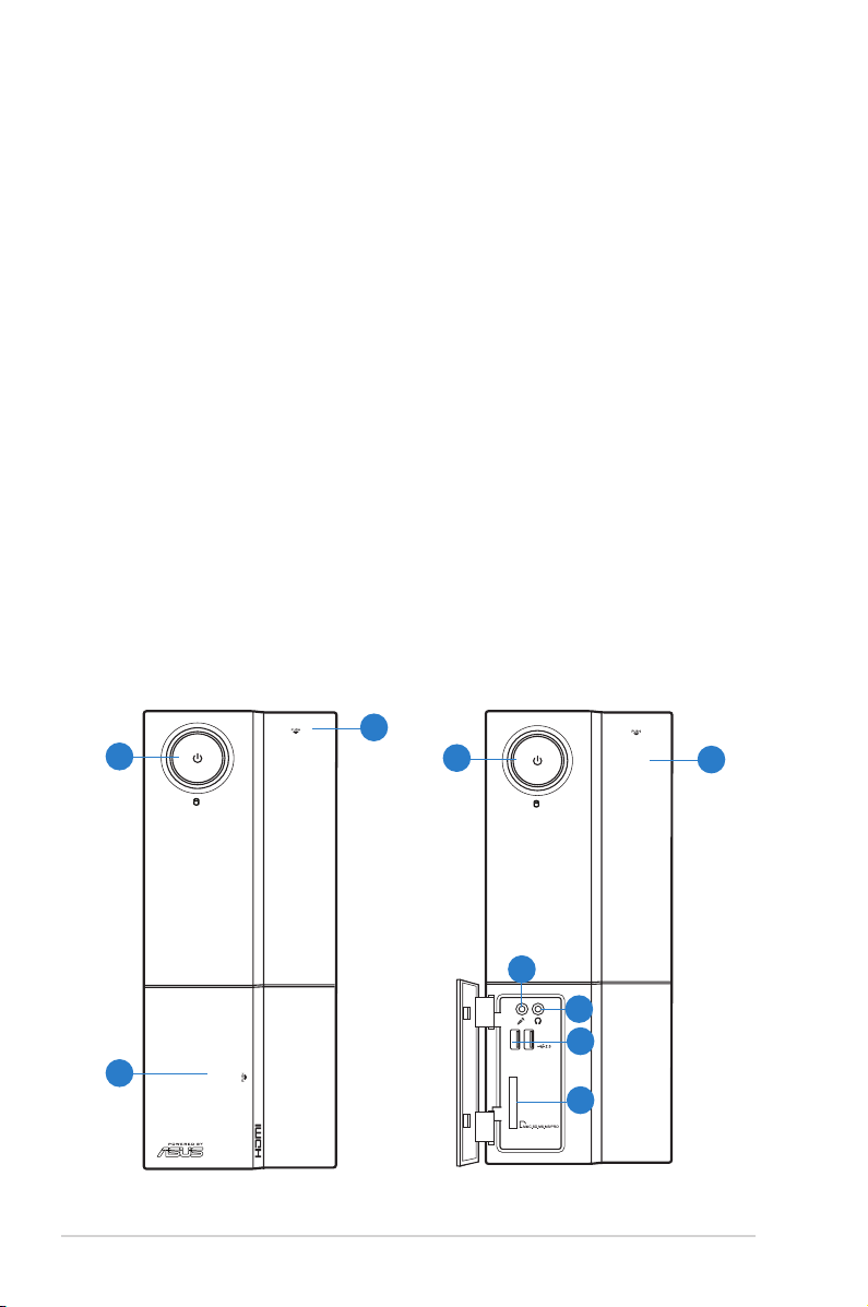
1.2 Front panel
The front panel includes the optical drive bays, power button, and several I/O ports
are located at the front panel.
3
1
1
3
4
5
6
2
7
1-2 Chapter 1: System introduction

1. Power button. Press this button to turn the system on.
2. Front panel cover. Push to open the front panel cover.
3. Optical disk drive cover. Push to eject the optical disk drive.
4. Microphone port. This Mic (pink) port connects a microphone.
5. Headphone port. This Line out (lime) port connects a headphone with a
stereo mini-plug.
6. USB 2.0 ports. These Universal Serial Bus 2.0 (USB 2.0) ports are available
for connecting USB 2.0 devices such as a mouse, printer, scanner, camera,
PDA, and others.
7. Multimedia Card / Secure Digital™ / MemoryStick® / Memory Stick
Pro™ card slot.
1-3ASUS P6-P7H55E
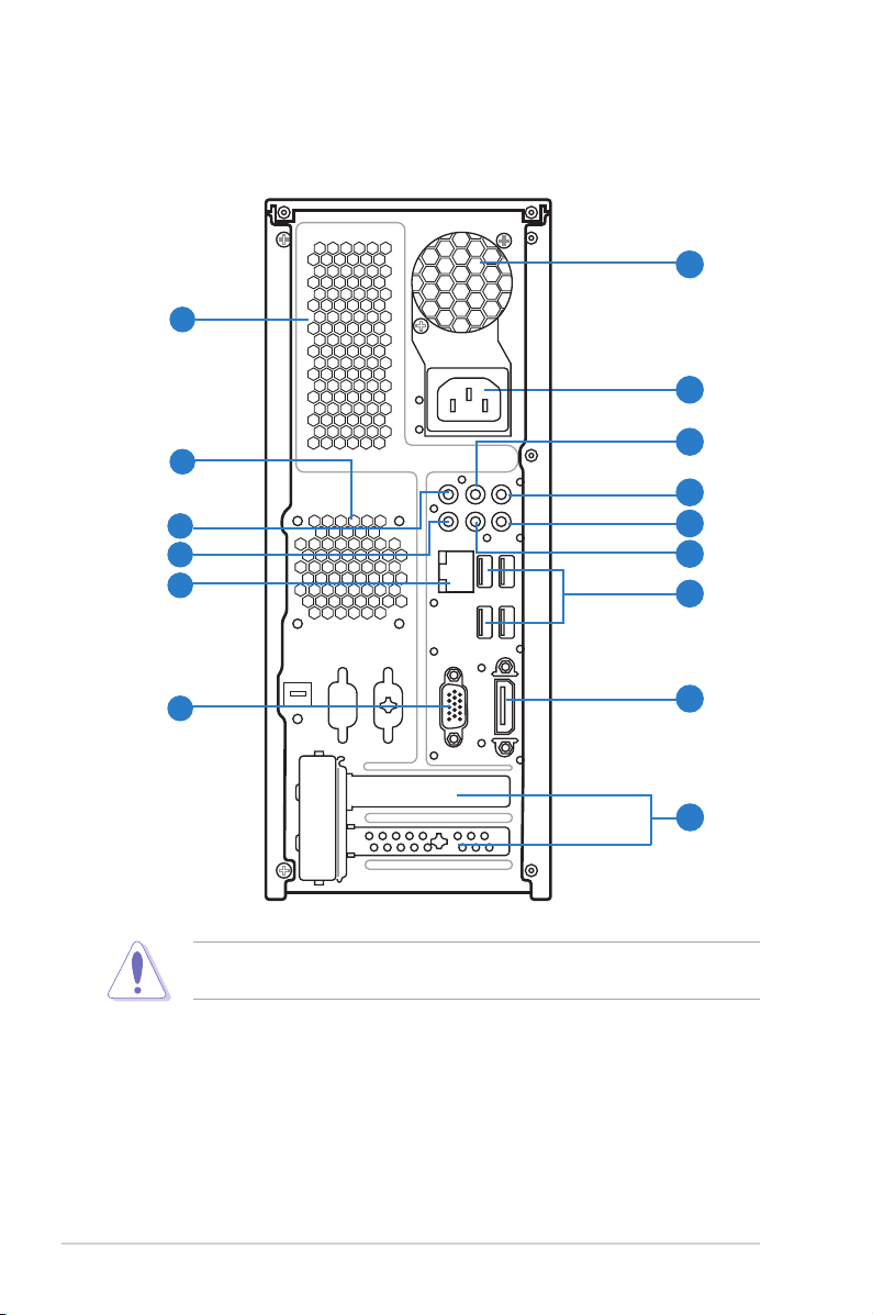
1.3 Rear panel
The system rear panel includes the power connector and several I/O ports that
allow convenient connection of devices.
2
1
4
3
5
10
11
13
Do NOT cover the rear vent , and the ambient temperature is limited up to 35oC
to prevent the system from overheating.
6
7
8
9
12
14
15
1. Chassis air vent. The vent is for ventilation inside the system chassis.
2. Power supply unit fan vent. This vent is for the PSU fan that provides
ventilation inside the power supply unit.
3. Chassis fan vent. This vent is for the fan that provides ventilation inside the
system chassis.
4. Power connector. This connector is for the power cable and plug.
1-4 Chapter 1: System introduction
5. LineInport(lightblue). This port connects the tape, CD, DVD player, or
other audio sources.
6. LineOutport(lime). This port connects a headphone or a speaker. In
4-channel, 6-channel, and 8-channel conguration, the function of this port
becomes Front Speaker Out.
7. Microphoneport(pink). This port connects a microphone.
8. SideSpeakerOutport(gray). This port connects the side speaker in an
8-channel audio conguration.
9. RearSpeakerOutport(black). This port connects the rear speakers in a
4-channel, 6-channel, or 8-channel audio conguration.
10. Center/Subwooferport(orange). This port connects the center/subwoofer
speakers.
Refer to the audio conguration table below for the function of the audio ports in
2, 4, 6, or 8-channel conguration.
Audio2,4,6,or8-channelconguration
Port
Light Blue Line In Line In Line In Line In
Lime Line Out Front Speaker Out Front Speaker Out Front Speaker Out
Pink Mic In Mic In Mic In Mic In
Orange – – Center/Subwoofer Center/Subwoofer
Black – Rear Speaker Out Rear Speaker Out Rear Speaker Out
Gray – – – Side Speaker Out
Headset
2-channel
4-channel 6-channel 8-channel
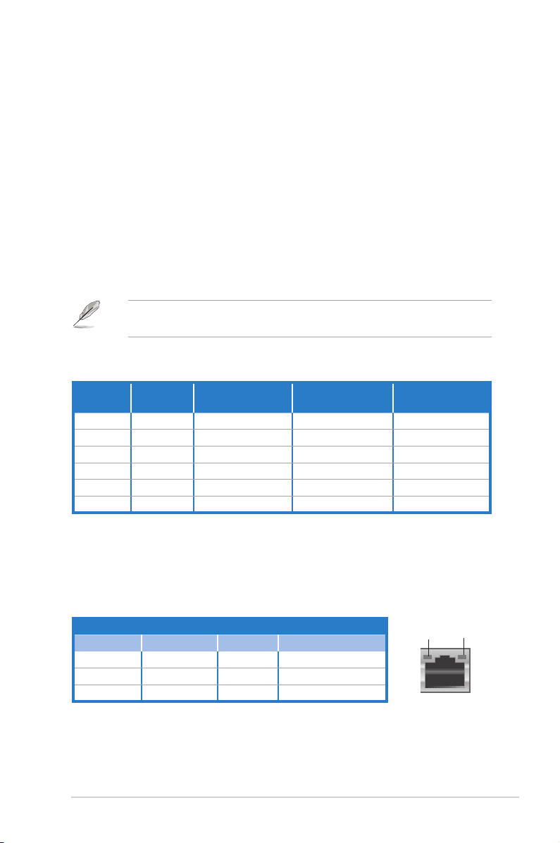
11. LAN(RJ-45)port. This port allows gigabit connection to a Local Area
Network (LAN) through a network hub. Refer to the table below for the LAN
port LED indications.
LANportLEDindications
Activity/Link SpeedLED
Status Description Status Description
OFF No link OFF 10 Mbps connection
ORANGE Linked ORANGE 100 Mbps connection
BLINKING Data activity GREEN 1 Gbps connection
ACT/LINK
LED
LANport
SPEED
LED
1-5ASUS P6-P7H55E

12. USB 2.0 ports 1 ~ 4. These 4-pin Universal Serial Bus (USB) ports are
available for connecting USB 2.0 devices.
13. VideoGraphicsAdapter(VGA)port. This 15-pin port is for a VGA monitor
or other VGA-compatible devices.
14. HDMI port. This is a High-Denition Mulltimedia Interface (HDMI) connector,
and is HDCP compliant allowing playback of HD DVD, Blu-Rau discs, and
other protected content.
15. Expansion slot covers. Remove these covers when installing expansion
cards.
1-6 Chapter 1: System introduction
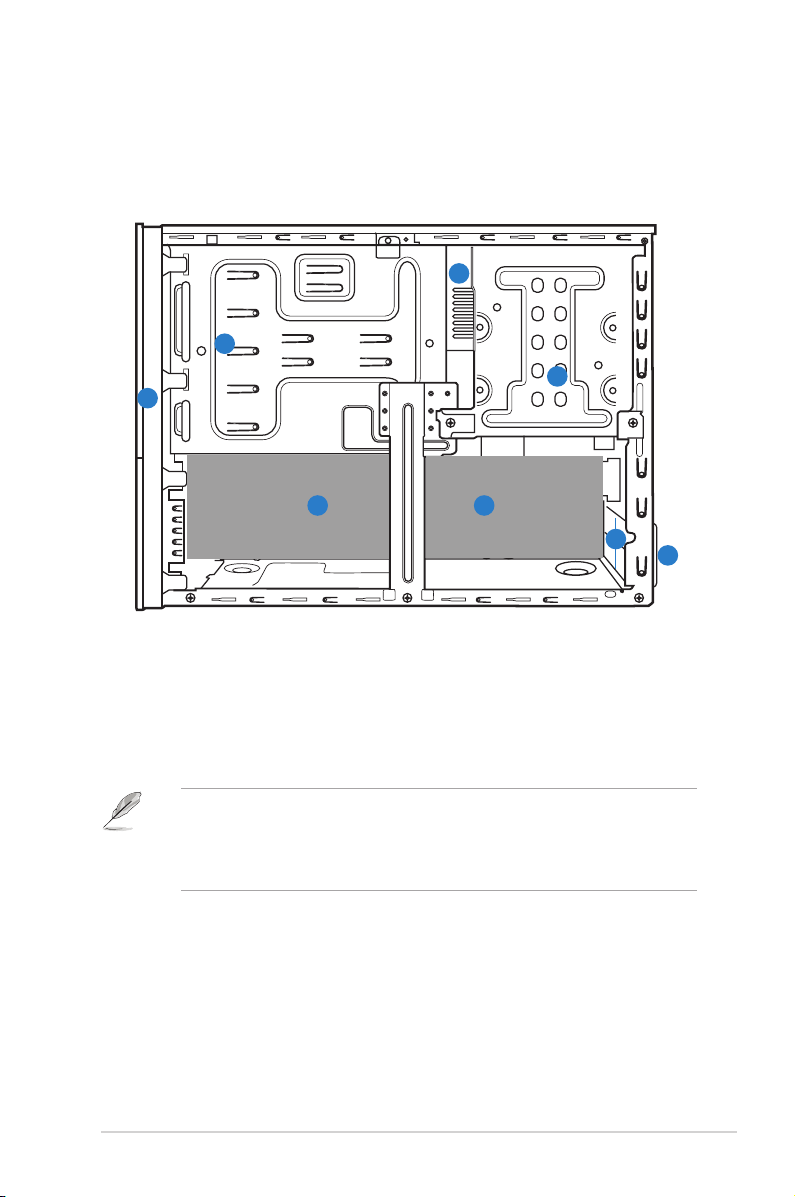
1.4 Internal components
The illustration below is the internal view of the system when you remove the side
cover and the power supply unit. The installed components are labeled for your
reference.
4
2
3
1
5
1. Front panel cover
2. 5.25-inch optical drive bays
3. Hard disk drive bay
5. ASUS motherboard
6. Expansion slot metal brackets
7. Metal bracket lock
4. Power supply unit (under the HDD bay)
• Refer to the bundled Quick Installation Guide for installing additional
system components and get assistance from professionals when you
disassemble or assemble the system.
• Refer to the Chapter 4 in this user guide for motherboard details.
5
6
7
1-7ASUS P6-P7H55E

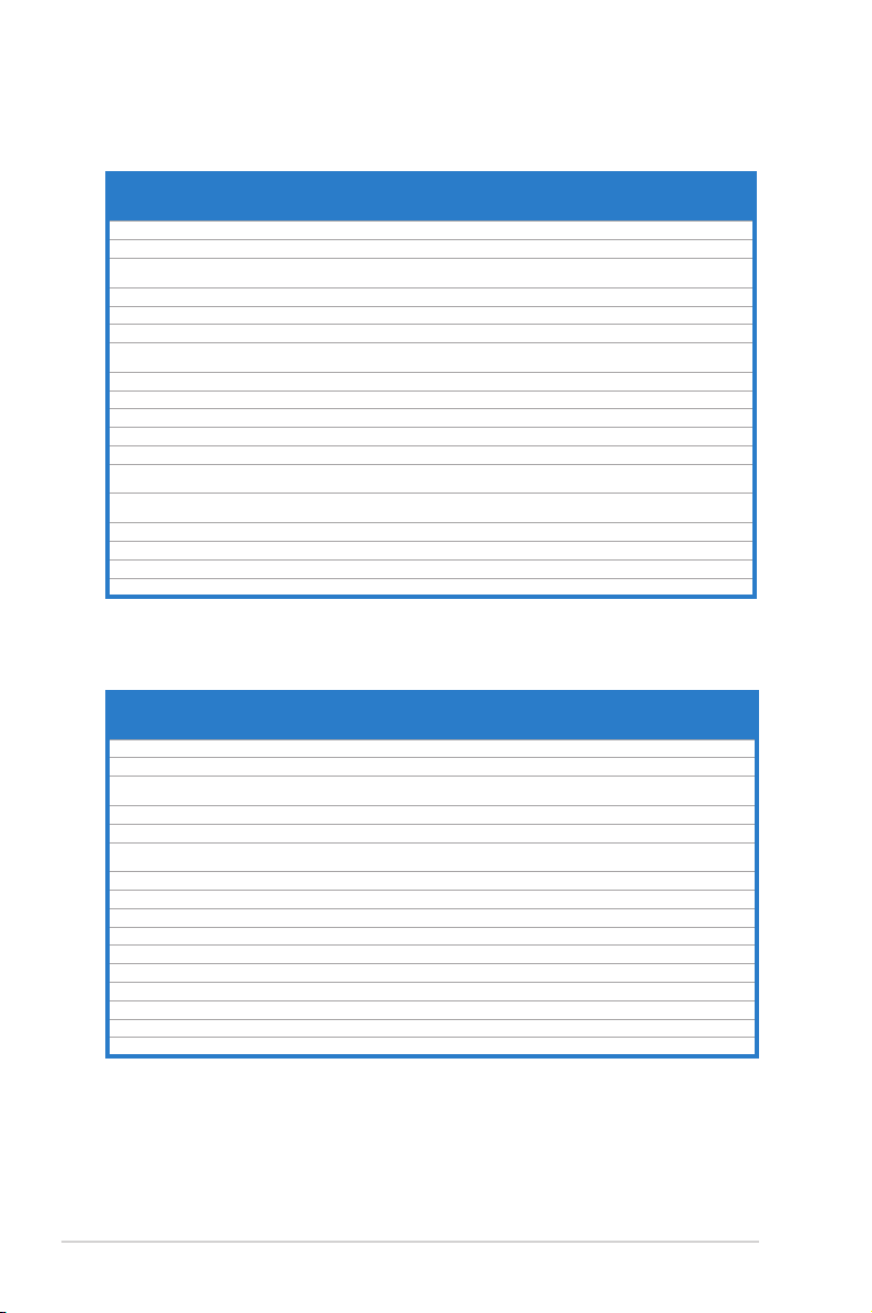
1.5 QualiedVendorsLists(QVL)
DDR3-1333MHzcapabilityforLynneldCPU(2.66GHz,2.8GHz,&2.93GHz)
DIMM socket
Vendor Part No. Size
A-Data AD31333001GOU 1024MB SS A-Data
A-Data AD31333G001GOU 3072MB(Kit of 3) SS - - 8-8-8-24
A-Data AD31333002GOU 2048MB DS A-Data
A-Data AD31333G002GMU 2048MB DS - - 8-8-8-24
Apacer 78.A1GC6.9L1 2048MB DS APACER AM5D5808DEWSBG - - • •
CORSAIR CM3X1024-1333C9DHX 1024MB SS - - 9-9-9-24 1.60V • •
CORSAIR CM3X1024-1333C9 1024MB SS - - 9-9-9-24 1.60V • •
CORSAIR TR3X3G1333C9 G 3072MB(Kit of 3) SS - - 9-9-9-24 1.50V • •
CORSAIR TR3X3G1333C9 G 3072MB(Kit of 3) SS - - 9-9-9-24 1.50V • •
CORSAIR TR3X3G1333C9 3072MB(Kit of 3) SS - - 9 1.5V • •
CORSAIR CM3X1024-1333C9DHX 1024MB DS Corsair - - - • •
CORSAIR CM3X2048-1333C9DHX 2048MB DS - - - - • •
CORSAIR TW3X4G1333C9 G 4096MB(Kit of 2) DS - - 9-9-9-24 1.50V • •
CORSAIR CMX8GX3M4A1333C9 8192MB(Kit of 4) DS - -
Crucial CT12864BA1339.8FF 1024MB SS Micron 9FF22D9KPT 9 - • •
Crucial BL12864TA1336.8SFB1 2048MB(Kit of 2) SS - - 6-6-6-20 1.8V • •
Crucial CT25664BA1339.16FF 2048MB DS Micron 9KF27D9KPT 9 - • •
Crucial BL25664ABA1336.16SFB1 4096MB(Kit of 2) DS - - 6-6-6-20 1.8V • •
Crucial BL25664BA1336.16SFB1 4096MB(Kit of 2) DS - - 6-6-6-20 1.8V • •
Crucial BL25664BN1337.16FF (XMP) 6144MB(Kit of 3) DS - - 7-7-7-24 1.65V • •
ELPIDA EBJ10UE8EDF0-DJ-F 1024MB SS ELPIDA J1108EDSE-DJ-F -
ELPIDA EBJ21UE8EDF0-DJ-F 2048MB DS ELPIDA J1108EDSE-DJ-F -
G.SKILL F3-10600CL7D-2GBPI(XMP) 1024MB SS G.SKILL - - - • •
G.SKILL F3-10600CL8D-2GBHK 1024MB SS G.SKILL - - - • •
G.SKILL F3-10600CL9D-2GBPK 1024MB SS G.SKILL - - - • •
G.SKILL F3-10666CL7T-3GBPK 3072MB(Kit of 3) SS - - 7-7-7-18 1.5~1.6V • •
G.SKILL F3-10666CL9T-3GBNQ 3072MB(Kit of 3) SS - - 9-9-9-24 1.5~1.6V • •
G.SKILL F3-10600CL9D-2GBNQ 1024MB DS G.SKILL - - - • •
F3-10666CL8D-
G.SKILL
4GBECO(XMP)
G.SKILL F3-10666CL8D-4GBHK(XMP) 4096MB(Kit of 2) DS - - 8-8-8-21 1.5-1.6V • •
G.SKILL F3-10666CL7T-6GBPK(XMP) 6144MB(Kit of 3) DS - - 7-7-7-18 1.5~1.6V • •
G.SKILL F3-10666CL9T-6GBNQ 6144MB(Kit of 3) DS - - 9-9-9-24 1.5V~1.6V • •
GEIL GV32GB1333C9DC 2048MB(Kit of 2) DS - - 9-9-9-24 1.5V • •
GEIL GV34GB1333C7DC 2048MB DS - - 7-7-7-24 1.5V • •
GEIL GG34GB1333C9DC 4096MB(Kit of 2) DS GEIL GL1L128M88BA12N 9-9-9-24
GEIL GV34GB1333C9DC 4096MB(Kit of 2) DS - - 9-9-9-24 1.5V • •
Kingmax FLFD45F-B8MF9 1024MB SS Micron 8HD22D9JNM - - • •
Kingmax FLFD45F-B8MH9 MAES 1024MB SS Micron 9CF22D9KPT - - • •
Kingmax FLFE85F-B8MF9 2048MB DS Micron 8HD22D9JNM - - • •
Kingmax FLFE85F-B8MH9 MEES 2048MB DS Micron 9GF27D9KPT - - • •
KINGSTON KVR1333D3N9/1G 1024MB SS KTC D1288JELDPGD9U - - • •
KINGSTON KVR1333D3N9/2G 2048MB DS Qimonda IDSH1G-03A1F1C-13H - 1.5V • •
KINGSTON KVR1333D3N9/4G 4096MB DS Hynix H5TQ2G83AFR - - • •
Micron MT8JTF12864AZ-1G4F1 1024MB SS Micron 9FF22D9KPT 9 - • •
Micron MT16JTF25664AZ-1G4F1 2048MB DS Micron 9KF27D9KPT 9 - • •
4096MB(Kit of 2) DS - - 8-8-8-24
SS/DSChip
Brand
Chip NO. Timing Voltage
AD30908C8D-151C
E0906
AD30908C8D-151C
E0903
- - • •
- - • •
9--99-24
continued on the next page
support
(Optional)
A* B*
1.65-
1.85V
1.65-
1.85V
1.50V • •
1.35V(low
voltage)
1.35V(low
voltage)
1.35V(low
voltage)
1.3V(low
voltage)
• •
• •
• •
• •
• •
• •
1-8 Chapter 1: System introduction

DDR3-1333MHzcapabilityforLynneldCPU(2.66GHz,2.8GHz,&2.93GHz)
DIMM socket
Vendor Part No. Size
OCZ OCZ3P13332GK 2048MB(Kit of 2) SS - - 7-7-7-20 1.8V • •
OCZ OCZ3X1333LV3GK(XMP) 3072MB(Kit of 3) SS - - - 1.6V • •
OCZ OCZ3G13334GK 4096MB(Kit of 2) DS - - - 1.7V • •
OCZ OCZ3P13334GK 4096MB(Kit of 2) DS - - 7-7-7-20 1.8V • •
OCZ OCZ3P1333LV4GK 4096MB(Kit of 2) DS - - 7-7-7-20 1.65V • •
OCZ OCZ3P1333LV4GK 4096MB(Kit of 2) DS - - 7-7-7-20 1.65V • •
OCZ OCZ3X13334GK(XMP) 4096MB(Kit of 2) DS - - 7-7-7-20 1.75V • •
OCZ OCZ3G1333LV6GK 6144MB(Kit of 3) DS - - 9-9-9-20 1.65V •
OCZ OCZ3P1333LV6GK 6144MB(Kit of 3) DS - - 7-7-7-20 1.65V • •
OCZ OCZ3X1333LV6GK(XMP) 6144MB(Kit of 3) DS - - 8-8-8-20 1.60V • •
PSC AL7F8G73D-DG1 1024MB SS PSC A3P1GF3DGF928M9B05 8-8-8-24 1.5V • •
PSC AL8F8G73D-DG1 2048MB DS PSC A3P1GF3DGF928M9B05 8-8-8-24 1.5V • •
SAMSUNG M378B2873DZ1-CH9 1024MB SS Samsung K4B1G0846D-HCH9 - - • •
SAMSUNG M378B2873DZ1-CH9 1024MB SS SAMSUNG
SAMSUNG M378B2873EH1-CH9 1024MB SS Samsung
SAMSUNG M378B5673DZ1-CH9 2048MB DS Samsung K4B1G0846D-HCH9 - - • •
SAMSUNG M378B5673EH1-CH9 2048MB DS Samsung
Super
W1333X2GB8(XMP) 1024MB SS - - - - • •
Talent
Transcend TS256MLK64V3U 2048MB DS Micron 9GF27D9KPT - - • •
ASINT SLY3128M8-EDJ 1024MB SS ASINT DDRII1208-DJ 0844 - - • •
ASINT SLY3128M8-EDJE 1024MB SS ELPIDA J1108BASE-DJ-E - - • •
ASINT SLZ3128M8-EDJE 2048MB DS ELPIDA J1108BASE-DJ-E - - • •
BUFFALO FSX1333D3G-K2G 1024MB SS - - 7-7-7-20 - • •
BUFFALO FSX1333D3G-2G 2048MB DS - - 7-7-7-20 -
Century PC3-10600 DDR3-1333 9-9-9 1024MB SS Micron 8FD22D9JNM - - • •
Elixir M2Y2G64CB8HA9N-CG 2048MB DS - - 7-7-7-20 - • •
Elixir M2Y2G64CB8HC9N-CG 2048MB DS Elixir - - - • •
Kingtiger 2GB DIMM PC3-10666 2048MB DS Samsung
Kingtiger KTG2G1333PG3 2048MB DS - - - - • •
PATRIOT PSD31G13332H 1024MB DS - - 9 - • •
PATRIOT PSD31G13332 1024MB DS Patriot PM64M8D38U-15 - - • •
PATRIOT PSD32G13332H 2048MB DS - - - - • •
SILICON
SP001GBLTU133S01 1024MB SS NANYA NT5CB128M8AN-CG 9 - • •
POWER
SILICON
SP001GBLTU133S02 1024MB SS elixir N2CB1680AN-C6 9 - • •
POWER
SILICON
SP002GBLTU133S02 2048MB DS elixir N2CB1680AN-C6 9 - • •
POWER
TAKEMS TMS1GB364D081-107EY 1024MB SS - - 7-7-7-20 1.5V • •
TAKEMS TMS1GB364D081-138EY 1024MB SS - - 8-8-8-24 1.5V • •
TAKEMS TMS2GB364D081-107EY 2048MB DS - - 7-7-7-20 1.5V • •
TAKEMS TMS2GB364D081-138EY 2048MB DS - - 8-8-8-24 1.5V • •
TAKEMS TMS2GB364D082-138EW 2048MB DS - - 8-8-8-24 1.5V • •
UMAX E41302GP0-73BDB 2048MB DS UMAX U2S24D30TP-13 - - • •
SS/DSChip
Brand
Chip NO. Timing Voltage
SEC 846 HCH9
K4B1G08460
SEC 913 HCH9
K4B1G0846E
SEC 913 HCH9
K4B1G0846E
SEC 904 HCH9
K4B1G0846D
- - • •
- - • •
- - • •
- - • •
support
(Optional)
A* B*
1-9ASUS P6-P7H55E
DDR3-1066MHzcapabilityforLynneldCPU(2.66GHz,2.8GHz,&2.93GHz)
DIMM socket
1.35V(low
voltage)
1.35V(low
voltage)
support(Optional)
A* B*
• •
• •
Vendor Part No. Size SS/DS Chip Brand Chip NO. Timing Voltage
Crucial CT12864BA1067.8FF 1024MB SS Micron 9GF22D9KPT 7 - • •
Crucial CT25664BA1067.16FF 2048MB DS Micron 9HF22D9KPT 7 - • •
ELPIDA EBJ10UE8EDF0-AE-F 1024MB SS ELPIDA J1108EDSE-DJ-F -
ELPIDA EBJ51UD8BAFA-AC-E 512MB SS Elpida J5308BASE-AC-E - - • •
ELPIDA EBJ51UD8BAFA-AE-E 512MB SS Elpida J5308BASE-AC-E - - • •
ELPIDA EBJ11UD8BAFA-AE-E 1024MB DS Elpida J5308BASE-AC-E - - • •
ELPIDA EBJ21UE8EDF0-AE-F 2048MB DS ELPIDA J1108EDSE-DJ-F -
KINGSTON KVR1066D3N7/1G 1024MB SS Kingston D1288JEKAPGA7U 7 1.5V • •
KINGSTON KVR1066D3N7/2G 2048MB DS Kingston D1288JEKAPGA7U 7 1.5V • •
KINGSTON KVR1066D3N7/4G 4096MB DS Hynix H5TQ2G83AFR 7 1.5V • •
Micron MT8JTF12864AZ-1G1F1 1024MB SS Micron 9GF22D9KPT 7 - • •
Micron MT16JTF25664AZ-1G1F1 2048MB DS Micron 9HF22D9KPT 7 - • •
SAMSUNG M378B2873EH1-CF8 1024MB SS Samsung
SAMSUNG M378B5273BH1-CF8 4096MB DS SAMSUNG
Elixir M2Y2G64CB8HC5N-BE 2048MB DS Elixir N2CB1G80CN-BE - - • •
Elixir M2Y2G64CBHA9N-BE 2048MB DS - - 7-7-7-20 - • •
Elixir M2Y2G64CBHC9N-BE 2048MB DS Elixir - - - • •
Kingtiger 2GB DIMM PC3-8500 2048MB DS Hynix H5TQ1G83AFP G7C - - • •
SEC 901 HCF8
K4B1G0846E
846 K4B2G0846B-
HCF8
- - • •
- - • •
DDR3-1066MHzcapabilityforClarkdaleCPU(2.00GHz)
1.35V(low
voltage)
1.35V(low
voltage)
DIMM socket
support(Optional)
A* B*
•
•
Vendor Part No. Size
Crucial CT12864BA1067.8FF 1024MB SS Micron 9GF22D9KPT 7 - •
Crucial CT25664BA1067.16FF 2048MB DS Micron 9HF22D9KPT 7 - •
ELPIDA EBJ10UE8EDF0-AE-F 1024MB SS ELPIDA J1108EDSE-DJ-F -
ELPIDA EBJ51UD8BAFA-AC-E 512MB SS Elpida J5308BASE-AC-E - - •
ELPIDA EBJ11UD8BAFA-AE-E 1024MB DS Elpida J5308BASE-AC-E - - •
ELPIDA EBJ21UE8EDF0-AE-F 2048MB DS ELPIDA J1108EDSE-DJ-F -
KINGSTON KVR1066D3N7/2G 2048MB DS Kingston D1288JEKAPGA7U 7 1.5V •
KINGSTON KVR1066D3N7/4G 4096MB DS Hynix H5TQ2G83AFR 7 1.5V •
Micron MT8JTF12864AZ-1G1F1 1024MB SS Micron 9GF22D9KPT 7 - •
Micron MT16JTF25664AZ-1G1F1 2048MB DS Micron 9HF22D9KPT 7 - •
SAMSUNG M378B2873EH1-CF8 1024MB SS Samsung SEC 901 HCF8 K4B1G0846E - - •
SAMSUNG M378B5273BH1-CF8 4096MB DS SAMSUNG 846 K4B2G0846B-HCF8 - - •
Elixir M2Y2G64CB8HC5N-BE 2048MB DS Elixir N2CB1G80CN-BE - - •
Elixir M2Y2G64CBHA9N-BE 2048MB DS - - 7-7-7-20 - •
Elixir M2Y2G64CBHC9N-BE 2048MB DS Elixir - - - •
Kingtiger 2GB DIMM PC3-8500 2048MB DS Hynix H5TQ1G83AFP G7C - - • •
SS/DSChip
Brand
Chip NO. Timing Voltage
1-10 Chapter 1: System introduction

DDR3-1333MHzcapabilityforClarkdaleCPU(2.00GHz)
DIMM socket
1.35V(low
voltage)
1.35V(low
voltage)
1.35V(low
voltage)
1.3V(low
voltage)
support
(Optional)
A* B*
• •
• •
• •
• •
Vendor Part No. Size
A-Data AD31333001GOU 1024MB SS A-Data
A-Data AD31333G001GOU 3072MB(Kit of 3) SS - - 8-8-8-24 1.65-1.85V •
A-Data AD31333002GOU 2048MB DS A-Data
A-Data AD31333G002GMU 2048MB DS - - 8-8-8-24 1.65-1.85V •
Apacer 78.A1GC6.9L1 2048MB DS APACER AM5D5808DEWSBG - - •
CORSAIR CM3X1024-1333C9DHX 1024MB SS - - 9-9-9-24 1.60V •
CORSAIR CM3X1024-1333C9 1024MB SS - - 9-9-9-24 1.60V •
CORSAIR TR3X3G1333C9 G 3072MB(Kit of 3) SS - - 9-9-9-24 1.50V •
CORSAIR TR3X3G1333C9 G 3072MB(Kit of 3) SS - - 9-9-9-24 1.50V •
CORSAIR TR3X3G1333C9 3072MB(Kit of 3) SS - - 9 1.5V • •
CORSAIR CM3X1024-1333C9DHX 1024MB DS Corsair - - - • •
CORSAIR CM3X2048-1333C9DHX 2048MB DS - - - - • •
CORSAIR TW3X4G1333C9 G 4096MB(Kit of 2) DS - - 9-9-9-24 1.50V • •
CORSAIR CMX8GX3M4A1333C9 8192MB(Kit of 4) DS - - 9-9-9-24 1.50V • •
Crucial CT12864BA1339.8FF 1024MB SS Micron 9FF22D9KPT 9 - • •
Crucial BL12864TA1336.8SFB1 2048MB(Kit of 2) SS - - 6-6-6-20 1.8V • •
Crucial CT25664BA1339.16FF 2048MB DS Micron 9KF27D9KPT 9 - • •
Crucial BL25664ABA1336.16SFB1 4096MB(Kit of 2) DS - - 6-6-6-20 1.8V • •
Crucial BL25664BA1336.16SFB1 4096MB(Kit of 2) DS - - 6-6-6-20 1.8V • •
Crucial BL25664BN1337.16FF (XMP) 6144MB(Kit of 3) DS - - 7-7-7-24 1.65V • •
ELPIDA EBJ10UE8EDF0-DJ-F 1024MB SS ELPIDA J1108EDSE-DJ-F -
ELPIDA EBJ21UE8EDF0-DJ-F 2048MB DS ELPIDA J1108EDSE-DJ-F -
G.SKILL F3-10600CL7D-2GBPI(XMP) 1024MB SS G.SKILL - - - • •
G.SKILL F3-10600CL8D-2GBHK 1024MB SS G.SKILL - - - • •
G.SKILL F3-10600CL9D-2GBPK 1024MB SS G.SKILL - - - • •
G.SKILL F3-10666CL7T-3GBPK 3072MB(Kit of 3) SS - - 7-7-7-18 1.5~1.6V • •
G.SKILL F3-10666CL9T-3GBNQ 3072MB(Kit of 3) SS - - 9-9-9-24 1.5~1.6V • •
G.SKILL F3-10600CL9D-2GBNQ 1024MB DS G.SKILL - - - • •
G.SKILL F3-10666CL8D-4GBECO(XMP) 4096MB(Kit of 2) DS - -
G.SKILL F3-10666CL8D-4GBHK(XMP) 4096MB(Kit of 2) DS - - 8-8-8-21 1.5-1.6V • •
G.SKILL F3-10666CL7T-6GBPK(XMP) 6144MB(Kit of 3) DS - - 7-7-7-18 1.5~1.6V • •
G.SKILL F3-10666CL9T-6GBNQ 6144MB(Kit of 3) DS - - 9-9-9-24 1.5V~1.6V • •
GEIL GV32GB1333C9DC 2048MB(Kit of 2) DS - - 9-9-9-24 1.5V • •
GEIL GV34GB1333C7DC 2048MB DS - - 7-7-7-24 1.5V • •
GEIL GG34GB1333C9DC 4096MB(Kit of 2) DS GEIL GL1L128M88BA12N 9-9-9-24
GEIL GV34GB1333C9DC 4096MB(Kit of 2) DS - - 9-9-9-24 1.5V • •
Kingmax FLFD45F-B8MF9 1024MB SS Micron 8HD22D9JNM - - • •
Kingmax FLFD45F-B8MH9 MAES 1024MB SS Micron 9CF22D9KPT - - • •
Kingmax FLFE85F-B8MF9 2048MB DS Micron 8HD22D9JNM - - • •
Kingmax FLFE85F-B8MH9 MEES 2048MB DS Micron 9GF27D9KPT - - • •
SS/DSChip
Brand
Chip NO. Timing Voltage
AD30908C8D-151C
E0906
AD30908C8D-151C
E0903
- - •
- - •
8-8-88-24
continued on the next page
1-11ASUS P6-P7H55E

DDR3-1333MHzcapabilityforClarkdaleCPU(2.00GHz)
DIMM socket
Vendor Part No. Size
KINGSTON KVR1333D3N9/1G 1024MB SS KTC D1288JELDPGD9U - - • •
KINGSTON KVR1333D3N9/2G 2048MB DS Qimonda IDSH1G-03A1F1C-13H - 1.5V
KINGSTON KVR1333D3N9/4G 4096MB DS Hynix H5TQ2G83AFR -- -
Micron MT8JTF12864AZ-1G4F1 1024MB SS Micron 9FF22D9KPT 9 -
Micron MT16JTF25664AZ-1G4F1 2048MB DS Micron 9KF27D9KPT 9 -
OCZ OCZ3P13332GK 2048MB(Kit of 2) SS - - 7-7-7-20 1.8V
OCZ OCZ3X1333LV3GK(XMP) 3072MB(Kit of 3) SS - - - 1.8V
OCZ OCZ3G13334GK 4096MB(Kit of 2) DS - - - 1.7V • •
OCZ OCZ3P13334GK 4096MB(Kit of 2) DS - - 7-7-7-20 1.8V • •
OCZ OCZ3P1333LV4GK 4096MB(Kit of 2) DS - - 7-7-7-20 1.65V • •
OCZ OCZ3P1333LV4GK 4096MB(Kit of 2) DS - - 7-7-7-20 1.65V • •
OCZ OCZ3RPX1333EB4GK 4096MB(Kit of 2) DS - - 6-5-5-20 1.85V • •
OCZ OCZ3X13334GK(XMP) 4096MB(Kit of 2) DS - - 7-7-7-20 1.75V • •
OCZ OCZ3G1333LV6GK 6144MB(Kit of 3) DS - - 9-9-9-20 1.65V • •
OCZ OCZ3P1333LV6GK 6144MB(Kit of 3) DS - - 7-7-7-20 1.65V • •
OCZ OCZ3X1333LV6GK(XMP) 6144MB(Kit of 3) DS - - 8-8-8-20 1.60V • •
PSC AL7F8G73D-DG1 1024MB SS PSC A3P1GF3DGF928M9B05 8-8-8-24 1.5V • •
PSC AL8F8G73D-DG1 2048MB DS PSC A3P1GF3DGF928M9B05 8-8-8-24 1.5V • •
SAMSUNG M378B2873DZ1-CH9 1024MB SS Samsung K4B1G0846D-HCH9 - - • •
SAMSUNG M378B2873DZ1-CH9 1024MB SS SAMSUNG
SAMSUNG M378B2873EH1-CH9 1024MB SS Samsung
SAMSUNG M378B5673DZ1-CH9 2048MB DS Samsung K4B1G0846D-HCH9 - - • •
SAMSUNG M378B5673EH1-CH9 2048MB DS Samsung
Super
W1333X2GB8(XMP) 1024MB SS - - - - • •
Talent
Transcend JM1333KLU-1G 1024MB SS Transcend TK243EDF3 9 - • •
Transcend JM1333KLU-2G 2048MB DS Transcend TK243EAF3 9 - • •
Transcend TS256MLK64V3U 2048MB DS Micron 9GF27D9KPT - - • •
ASINT SLY3128M8-EDJ 1024MB SS ASINT DDRII1208-DJ 0844 - - • •
ASINT SLY3128M8-EDJE 1024MB SS ELPIDA J1108BASE-DJ-E - - • •
ASINT SLY3128M8-EDJ 2048MB DS ASINT DDRII1208-DJ 0844 - - • •
ASINT SLZ3128M8-EDJE 2048MB DS ELPIDA J1108BASE-DJ-E - - • •
BUFFALO FSX1333D3G-K2G 1024MB SS - - 7-7-7-20 - • •
BUFFALO FSX1333D3G-2G 2048MB DS - - 7-7-7-20 - • •
Century PC3-10600 DDR3-1333 9-9-9 1024MB SS Micron 8FD22D9JNM - - • •
Century PC3-10600 DDR3-1333 9-9-9 2048MB DS Micron 8DD22D9JNM - - • •
Elixir M2Y2G64CB8HA9N-CG 2048MB DS - - 7-7-7-20 - • •
Elixir M2Y2G64CB8HC9N-CG 2048MB DS Elixir - - - • •
Kingtiger 2GB DIMM PC3-10666 2048MB DS Samsung
Kingtiger KTG2G1333PG3 2048MB DS - - - - • •
PATRIOT PSD31G13332H 1024MB DS - - 9 - • •
PATRIOT PSD31G13332 1024MB DS Patriot PM64M8D38U-15 - - • •
PATRIOT PSD32G13332H 2048MB DS - - - - • •
PATRIOT PDC34G1333ELK 4096MB(Kit of 2) DS - - 9-9-9-24 1.5V • •
SS/DSChip
Brand
Chip NO. Timing Voltage
SEC 846 HCH9
K4B1G08460
SEC 913 HCH9
K4B1G0846E
SEC 913 HCH9
K4B1G0846E
SEC 904 HCH9
K4B1G0846D
- - • •
- - • •
- - • •
- - • •
continued on the next page
support
(Optional)
A* B*
1-12 Chapter 1: System introduction
 Loading...