


P5N73-CM
Table of contents
 Loading...
Motherboard
P5N73-CM

ii
E4407
Second Edition V2
December 2008
Copyright © 2008 ASUSTeK Computer, Inc. All Rights Reserved.
No part of this manual, including the products and software described in it, may be reproduced,
transmitted, transcribed, stored in a retrieval system, or translated into any language in any form or by any
means, except documentation kept by the purchaser for backup purposes, without the express written
permission of ASUSTeK Computer Inc. (“ASUS”).
Product warranty or service will not be extended if: (1) the product is repaired, modied or altered, unless
such repair, modication of alteration is authorized in writing by ASUS; or (2) the serial number of the
product is defaced or missing.
ASUS PROVIDES THIS MANUAL “AS IS” WITHOUT WARRANTY OF ANY KIND, EITHER EXPRESS
OR IMPLIED, INCLUDING BUT NOT LIMITED TO THE IMPLIED WARRANTIES OR CONDITIONS OF
MERCHANTABILITY OR FITNESS FOR A PARTICULAR PURPOSE. IN NO EVENT SHALL ASUS, ITS
DIRECTORS, OFFICERS, EMPLOYEES OR AGENTS BE LIABLE FOR ANY INDIRECT, SPECIAL,
INCIDENTAL, OR CONSEQUENTIAL DAMAGES (INCLUDING DAMAGES FOR LOSS OF PROFITS,
LOSS OF BUSINESS, LOSS OF USE OR DATA, INTERRUPTION OF BUSINESS AND THE LIKE),
EVEN IF ASUS HAS BEEN ADVISED OF THE POSSIBILITY OF SUCH DAMAGES ARISING FROM ANY
DEFECT OR ERROR IN THIS MANUAL OR PRODUCT.
SPECIFICATIONS AND INFORMATION CONTAINED IN THIS MANUAL ARE FURNISHED FOR
INFORMATIONAL USE ONLY, AND ARE SUBJECT TO CHANGE AT ANY TIME WITHOUT NOTICE,
AND SHOULD NOT BE CONSTRUED AS A COMMITMENT BY ASUS. ASUS ASSUMES NO
RESPONSIBILITY OR LIABILITY FOR ANY ERRORS OR INACCURACIES THAT MAY APPEAR IN THIS
MANUAL, INCLUDING THE PRODUCTS AND SOFTWARE DESCRIBED IN IT.
Products and corporate names appearing in this manual may or may not be registered trademarks or
copyrights of their respective companies, and are used only for identication or explanation and to the
owners’ benet, without intent to infringe.

iii
Contents
Notices ......................................................................................................... vi
Safety information
..................................................................................... vii
About this guide
........................................................................................ vii
P5N73-CM specications summary .......................................................... ix
Chapter 1 Product introduction
1.1 Welcome! ...................................................................................... 1-1
1.2 Package contents
......................................................................... 1-1
1.3 Special features
............................................................................ 1-1
1.3.1 Product highlights ...........................................................
1-1
1.3.2 Innovative ASUS features ...............................................
1-3
1.4 Before you proceed
..................................................................... 1-4
1.5 Motherboard overview
................................................................. 1-5
1.5.1 Placement direction ........................................................
1-5
1.5.2 Screw holes ....................................................................
1-5
1.5.3 Motherboard layout .........................................................
1-6
1.5.4 Layout contents ...............................................................
1-6
1.6 Central Processing Unit (CPU)
................................................... 1-7
1.6.1 Installing the CPU ...........................................................
1-7
1.6.2 Installing the CPU heatsink and fan ..............................
1-10
1.6.3 Uninstalling the CPU heatsink and fan ..........................
1-11
1.7 System memory
......................................................................... 1-12
1.7.1 Overview .......................................................................
1-12
1.7.2 Memory congurations ..................................................
1-13
1.7.3 Installing a DIMM ..........................................................
1-17
1.7.4 Removing a DIMM ........................................................
1-17
1.8 Expansion slots
.......................................................................... 1-18
1.8.1 Installing an expansion card .........................................
1-18
1.8.2 Conguring an expansion card .....................................
1-18
1.8.3 PCI slots ........................................................................
1-18
1.8.4 PCI Express x1 slots .....................................................
1-18
1.8.5 PCI Express x16 slot .....................................................
1-18
1.9 Jumpers
...................................................................................... 1-19
1.10 Connectors
................................................................................. 1-20
1.10.1 Rear panel connectors ..................................................
1-20
1.10.2 Internal connectors .......................................................
1-21

iv
Contents
1.11 Software support ........................................................................ 1-29
1.11.1 Installing an operating system ......................................
1-29
1.11.2 Support DVD information ..............................................
1-29
Chapter 2 BIOS information
2.1 Managing and updating your BIOS ............................................ 2-1
2.1.1 ASUS Update utility ........................................................
2-1
2.1.2 Creating a bootable oppy disk .......................................
2-2
2.1.3 ASUS EZ Flash 2 utility ...................................................
2-3
2.1.4 Updating the BIOS ..........................................................
2-4
2.1.5 Saving the current BIOS le ............................................
2-5
2.1.6 ASUS CrashFree BIOS 2 utility ......................................
2-6
2.2 BIOS setup program
.................................................................... 2-8
2.2.1 BIOS menu screen ..........................................................
2-9
2.2.2 Menu bar .........................................................................
2-9
2.2.3 Navigation keys ...............................................................
2-9
2.2.4 Menu items ...................................................................
2-10
2.2.5 Sub-menu items ............................................................
2-10
2.2.6 Conguration elds .......................................................
2-10
2.2.7 Pop-up window .............................................................
2-10
2.2.8 Scroll bar .......................................................................
2-10
2.2.9 General help .................................................................
2-10
2.3 Main menu
.................................................................................. 2-11
2.3.1 System Time ..................................................................
2-11
2.3.2 System Date ..................................................................
2-11
2.3.3 Legacy Diskette A ..........................................................
2-11
2.3.4 Primary IDE Master/Slave ..............................................
2-11
2.3.5 SATA 1-4 .......................................................................
2-12
2.3.6 HDD SMART Monitoring ...............................................
2-13
2.3.7 Installed Memory ...........................................................
2-13
2.3.8 Usable Memory .............................................................
2-13
2.4 Advanced menu
......................................................................... 2-14
2.4.1 JumperFree ...................................................................
2-14
2.4.2 AI NET 2
........................................................................ 2-15
2.4.3 CPU Conguration ........................................................
2-15
2.4.4 Chipset ..........................................................................
2-16

v
Contents
2.4.5 PCIPnP ......................................................................... 2-16
2.4.6 Onboard Device Conguration ......................................
2-17
2.4.7 USB Conguration ........................................................
2-18
2.5 Power menu
................................................................................ 2-18
2.5.1 ACPI Suspend Type ......................................................
2-19
2.5.2 ACPI APIC Support .......................................................
2-19
2.5.3 APM Conguration ........................................................
2-19
2.5.4 Hardware Monitor .........................................................
2-20
2.6 Boot menu
.................................................................................. 2-21
2.6.2 Removable Drives .........................................................
2-21
2.6.3 Boot Settings Conguration ..........................................
2-21
2.6.4 Security .........................................................................
2-22
2.7 Tools menu
................................................................................. 2-23
2.7.1
ASUS EZ Flash 2 .......................................................... 2-23
2.7.2 Express Gate ................................................................
2-23
2.8 Exit menu
.................................................................................... 2-24
vi
Notices
Federal Communications Commission Statement
This device complies with Part 15 of the FCC Rules. Operation is subject to the following two
conditions:
•
This device may not cause harmful interference, and
•
This device must accept any interference received including interference that may cause
undesired operation.
This equipment has been tested and found to comply with the limits for a Class B digital
device, pursuant to Part 15 of the FCC Rules. These limits are designed to provide
reasonable protection against harmful interference in a residential installation. This
equipment generates, uses and can radiate radio frequency energy and, if not installed
and used in accordance with manufacturer’s instructions, may cause harmful interference
to radio communications. However, there is no guarantee that interference will not occur
in a particular installation. If this equipment does cause harmful interference to radio or
television reception, which can be determined by turning the equipment off and on, the user
is encouraged to try to correct the interference by one or more of the following measures:
•
Reorient or relocate the receiving antenna.
•
Increase the separation between the equipment and receiver.
•
Connect the equipment to an outlet on a circuit different from that to which the receiver is
connected.
•
Consult the dealer or an experienced radio/TV technician for help.
Canadian Department of Communications Statement
This digital apparatus does not exceed the Class B limits for radio noise emissions from
digital apparatus set out in the Radio Interference Regulations of the Canadian Department
of Communications.
This class B digital apparatus complies with Canadian ICES-003.
The use of shielded cables for connection of the monitor to the graphics card is required
to assure compliance with FCC regulations. Changes or modications to this unit not
expressly approved by the party responsible for compliance could void the user’s authority
to operate this equipment.
DO NOT throw the motherboard in municipal waste. This product has been designed to
enable proper reuse of parts and recycling. This symbol of the crossed out wheeled bin
indicates that the product (electrical and electronic equipment) should not be placed in
municipal waste. Check local regulations for disposal of electronic products.
DO NOT throw the mercury-containing button cell battery in municipal waste. This symbol
of the crossed out wheeled bin indicates that the battery should not be placed in municipal
waste.

vii
Safety information
Electrical safety
•
To prevent electrical shock hazard, disconnect the power cable from the electrical outlet
before relocating the system.
•
When adding or removing devices to or from the system, ensure that the power cables
for the devices are unplugged before the signal cables are connected. If possible,
disconnect all power cables from the existing system before you add a device.
•
Before connecting or removing signal cables from the motherboard, ensure that all
power cables are unplugged.
•
Seek professional assistance before using an adpater or extension cord. These devices
could interrupt the grounding circuit.
• Make sure that your power supply is set to the correct voltage in your area. If you are
not sure about the voltage of the electrical outlet you are using, contact your local power
company.
•
If the power supply is broken, do not try to x it by yourself. Contact a qualied service
technician or your retailer.
Operation safety
•
Before installing the motherboard and adding devices on it, carefully read all the manuals
that came with the package.
•
Before using the product, make sure all cables are correctly connected and the power
cables are not damaged. If you detect any damage, contact your dealer immediately.
•
To avoid short circuits, keep paper clips, screws, and staples away from connectors,
slots, sockets and circuitry.
•
Avoid dust, humidity, and temperature extremes. Do not place the product in any area
where it may become wet.
•
Place the product on a stable surface.
•
If you encounter technical problems with the product, contact a qualied service
technician or your retailer.
About this guide
This user guide contains the information you need when installing and conguring the
motherboard.
How this guide is organized
This guide contains the following parts:
• Chapter 1: Product introduction
This chapter describes the features of the motherboard and the new technology it
supports.
• Chapter 2: BIOS setup
This chapter tells how to change system settings through the BIOS Setup menus.
Detailed descriptions of the BIOS parameters are also provided.
viii
Where to nd more information
Refer to the following sources for additional information and for product and software
updates.
1. ASUS websites
The ASUS website provides updated information on ASUS hardware and software
products. Refer to the ASUS contact information.
2. Optional documentation
Your product package may include optional documentation, such as warranty yers,
that may have been added by your dealer. These documents are not part of the
standard package.
Conventions used in this guide
To make sure that you perform certain tasks properly, take note of the following symbols used
throughout this manual.
DANGER/WARNING: Information to prevent injury to yourself
when trying to complete a task.
CAUTION: Information to prevent damage to the components
when trying to complete a task.
NOTE: Tips and additional information to help you complete a
task.
IMPORTANT: Instructions that you MUST follow to complete a
task.
Typography
Bold text Indicates a menu or an item to select.
Italics
Used to emphasize a word or a phrase.
<Key> Keys enclosed in the less-than and greater-than sign means
that you must press the enclosed key.
Example: <Enter> means that you must press the Enter or
Return key.
<Key1>+<Key2>+<Key3> If you must press two or more keys simultaneously, the key
names are linked with a plus sign (+).
Example: <Ctrl>+<Alt>+<D>
Command Means that you must type the command exactly as shown,
then supply the required item or value enclosed in brackets.
Example: At the DOS prompt, type the command line:
afudos /i[lename]
afudos /iP5N73CM.ROM
ix
P5N73-CM specications summary
(continued on the next page)
CPU LGA775 socket for Intel
®
Core™ 2 Extreme /
Core™ 2 Quad / Core™ 2 Duo / Pentium
®
D /
Pentium
®
4 / Celeron
®
E1000 Series and Celeron
®
400
Series processors
Supports Intel
®
next generation 45nm CPU
Supports Enhanced Intel SpeedStep
®
Technology (EIST)
Supports Intel
®
Hyper-Threading Technology
*Refer to www.asus.com for Intel CPU support list
Chipset NVIDIA GeForce 7100 / nForce 630i (MCP73PV)
Front Side Bus 1333 / 1066 / 800 MHz
Memory Single-channel memory architecture
2 x 240-pin DIMM sockets support unbufferred non-ECC
DDR2-800 / 667 memory
modules
Supports up to 4 GB system memory
Expansion Slots 1 x PCI Express x16 slot
1 x PCI Express x1 slot
2 x PCI slots
Audio VIA VT1708B, 8-CH High-Denation Audio CODEC
Storage Southbridge:
- 1 x Ultra DMA 133
- 4 x Serial ATA 3Gb/s devices
- RAID 0, RAID 1, RAID 0+1, RAID 5, and JBOD
conguration
LAN Realtek 8211CL Gb LAN
USB Supports up to 10 USB 2.0 ports (6 ports at mid-board, 4
ports at rear panel)
ASUS Special Features ASUS CrashFree BIOS 2
ASUS Q-Fan
ASUS EZ Flash 2
ASUS MyLogo 2
ASUS Express Gate
Rear panel 1 x DVI port
1 x COM port
1 x LAN (RJ-45) port
4 x USB 2.0 ports
1 x VGA port
1 x PS/2 keyboard port (purple)
1 x PS/2 mouse port (green)
8-channel audio I/O ports

x
P5N73-CM specications summary
*Specications are subject to change without notice.
Internal connectors 1 x Floppy Disk connector
1 x CD audio in connector
1 x 24-pin EPS 12V power connector
1 x 4-pin ATX 12 V power connector
3 x USB connectors for additional six USB 2.0 ports
1 x S/PDIF out connector
1 x Chassis intrusion connector
1 x Front panel High Denation audio connector
1 x LPT connector
1 x CPU Fan connector
1 x Chassis Fan connector
1 x Power Fan conncetor
System panel connector
VGA GeForce 7100 GPU supports maximum resolution of
1920 x1440 X32bpp (@ 75Hz)
BIOS features 8 MB Flash ROM, Award BIOS, Green, PnP, DMI v2.0,
WfM2.0, ACPI v2.0a, SMBIOS v2.5
Power Requirement ATX power supply (with 24-pin and 4-pin 12V plugs)
ATX 12V 2.0 compliant
Manageability WOL, PXE, WOR by Ring, PME Wake UP
Support CD contents Drivers
ASUS PC Probe II
ASUS Update
Anti-virus software
Form factor uATX Form Factor: 9.6 in x 8.4 in (24.5 cm x 21.3 cm)
ASUS P5N73-CM 1-1
Chapter 1
Product introduction
1.1 Welcome!
Thank you for buying an ASUS
®
P5N73-CM motherboard!
The motherboard delivers a host of new features and latest technologies, making it another
standout in the long line of ASUS quality motherboards!
Before you start installing the motherboard, and hardware devices on it, check the items in
your package with the list below.
1.2 Package contents
Check your motherboard package for the following items.
Motherboard ASUS P5N73-CM motherboard
Cables 1 x Serial ATA cable
1 x Serial ATA power cable
1 x Ultra DMA 133 cable
Accessories 1 x I/O shield
Application DVD ASUS motherboard support DVD
Documentation User Manual
If any of the above items is damaged or missing, contact your retailer.
1.3 Special features
1.3.1 Product highlights
LGA775 Intel
®
Quad-core Processor Ready
This motherboard supports the latest Intel® Quad-core processors in
LGA775 package. It also can support Intel® next generation 45nm Multi-
Core CPU. It´s excellent for multi-tasking, multi-media and enthusiastic
gamers with 1333/1066/800 MHz FSB.
1-2 Chapter 1: Product introduction
Intel
®
Core™2 Processor Ready
This motherboard supports the latest Intel® Core™2 processor in the
LGA775 package. With the new Intel
®
Core™ microarchitecture technology
and 1333 / 1066 / 800 MHz FSB, Intel
®
Core™2 processor is designed to
provide powerful and energy efcient performance.
NVIDIA Geforce 7100/ nForce 630i Chipset
The brand new NVIDIA® GeForce 7100 / nForce 630i MCP (Media and
Communications Processor) features CineFX™ 3.0 Engine. This unique
combination of MCP creates a single motherboard featuring a world-class
DX9, Shader Model 3.0 GPU for faster and smoother game-play, a high
quality video processing engine for advance quality of video and DVD
playback.
Serial ATA 3 Gb/s with RAID function
This motherboard supports the next-generation hard drives based on
the Serial ATA (SATA) 3 Gb/s storage specication, delivering enhanced
scalability and doubling the bus bandwidth for high-speed data retrieval
and saves. Easily backup photos, videos and other entertainment
contents to external devices. It allows RAID 0, RAID 1, RAID 5, RAID 10,
and JBOD congurations for four onboard SATA connectors.
Japan-made 5000hrs VRM Solid Capacitors
Stable system operation depends upon the quality of CPU VRM (voltage
regulator module). ASUS adopts Japan-made 5000hrs Conductive
Polymer Solid Capacitors CPU VRM to ensure a longer lifespan for
systems in daily operation and boost system stability under extreme
conditions. CPU VRM with Polymer Capacitors featuring better electronic
conductivity, excellent heat resistance enhances system durability even
operating in high temperature environment.
Gigabit LAN solution
The onboard LAN controller is a highly integrated Gb LAN controller. It is
enhanced with an ACPI management function to provide efcient power
management for advanced operating systems.
PCI Express Architecture
PCI Express is the latest I/O interconnect technology that will replace
the existing PCI. With a bus bandwidth 4 times higher than that of AGP
8X interface, PCI Express x16 bus performs much better than AGP 8X in
applications such as 3D gaming.
Max. 10 USB 2.0 ports supports
USB 2.0 is the latest connectivity standard for next generation
components and peripherals. Backwards compatible with current USB
1.1 peripherals, USB 2.0 delivers transfer speeds up to 40 times faster at
480Mb/s, for easy connectivity and ultra-fast data
ASUS P5N73-CM 1-3
8-Channel High Denition Audio
Enjoy high-end sound quality on your PC! The onboard 8-channel HD
audio (High Definition Audio, previously codenamed Azalia) CODEC
enables high-quality 192KHz / 24-bit audio output, jack-detect feature.
DVI Interface
DVI (Digital Visual Interface) provides high visual quality of digital display
devices such as LCD monitor. The interface of this motherboard is
HDCP compliant, allowing playback of HD DVD, Blu-ray Disc and other
protected content.
Dual VGA Output
This motherboard supports Dual-VGA output (RGB / DVI). DVI interface
is compliant with HDCP.
1.3.2 Innovative ASUS features
ASUS MyLogo2™
This feature allows you to convert your favorite photo into a 256-color
boot logo for a more colorful and vivid image on your screen.
ASUS CrashFree BIOS 2
This feature allows you to restore the original BIOS data from the support
CD in case when the BIOS codes and data are corrupted. This protection
eliminates the need to buy a replacement BIOS chip. See page 2-6 for
details.
ASUS EZ Flash 2
ASUS EZ Flash 2 is a utility that allows you to update the BIOS without
using a DOS-based utility.
Express Gate
Express Gate is a unique OS built into the motherboard. Five minutes
after bootup, you can instantly surf the Internet without entering the
Windows
®
OS.
• The actual boot time depends on the system conguration.
• ASUS Express Gate supports le uploading from SATA HDDs, ODDs and USB drives
and downloading to USB drives only.
ASUS Q-Fan technology
The ASUS Q-Fan technology smartly adjusts the fan speeds according to
the system loading to ensure quiet, cool, and efcient operation.
See page 2-34 for details.
Green ASUS
This motherboard and its packaging comply with the European Union’s
Restriction on the use of Hazardous Substances (RoHS). This is in line
with the ASUS vision of creating environment-friendly and recyclable
products/packaging to safeguard consumers’ health while minimizing the
impact on the environment.
1-4 Chapter 1: Product introduction
1.4 Before you proceed
Take note of the following precautions before you install motherboard components or change
any motherboard settings.
• Unplug the power cord from the wall socket before touching any component.
• Before handling components, use a grounded wrist strap or touch a safely grounded
object or a metal object, such as the power supply case, to avoid damaging them due to
static electricity.
• Hold components by the edges to avoid touching the ICs on them.
• Whenever you uninstall any component, place it on a grounded antistatic pad or in the
bag that came with the component.
• Before you install or remove any component, ensure that the ATX power supply is
switched off or the power cord is detached from the power supply. Failure to do so may
cause severe damage to the motherboard, peripherals, or components.
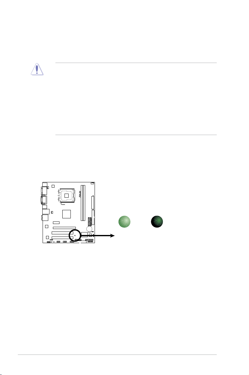
Onboard LED
The motherboard comes with a standby power LED that lights up to indicate that the
system is ON, in sleep mode, or in soft-off mode. This is a reminder that you must
shut down the system and unplug the power cable before removing or plugging in any
motherboard component. The illustration below shows the location of the onboard LED.
P5N73-CM Onboard LED
R
SB_PWR
ON
Standby
Power
OFF
Powered
Off
P5N73-CM
ASUS P5N73-CM 1-5
R
P5N73-CM
1.5 Motherboard overview
Before you install the motherboard, study the conguration of your chassis to ensure that the
motherboard ts into it.
Ensure that you unplug the power cord before installing or removing the motherboard.
Failure to do so can cause you physical injury and damage motherboard components.
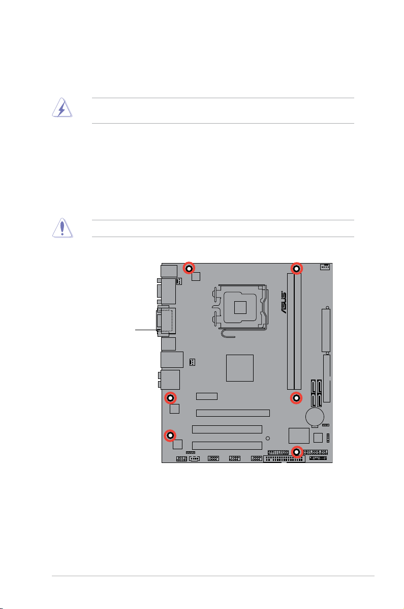
1.5.1 Placement direction
When installing the motherboard, ensure that you place it into the chassis in the correct
orientation. The edge with external ports goes to the rear part of the chassis as indicated in
the image below.
1.5.2 Screw holes
Place six screws into the holes indicated by circles to secure the motherboard to the chassis.
Do not overtighten the screws! Doing so can damage the motherboard.
Place this side towards
the rear of the chassis
1-6 Chapter 1: Product introduction
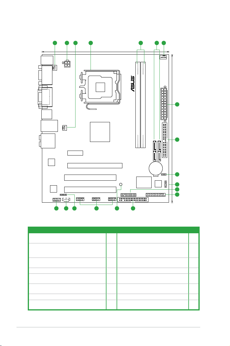
1.5.3 Motherboard layout
1.5.4 Layout contents
Connectors/Jumpers/Slots Page Connectors/Jumpers/Slots Page
1. CPU, chassis, and power fan connectors (4-pin
CPU_FAN, 3-pin CHA_FAN, 3-pin PWR_FAN)
1-21 9. System panel connector (20-8 pin PANEL) 1-25
2. ATX power connectors (24-pin EATXPWR, 4-pin
ATX12V)
1-22 10. LPT connector (26-1 pin LPT) Onboard
LED USB device wake-up (3-pin
USBPW5-8)
1-26
3. LGA775 CPU socket 1-7 11. Floppy disk drive connector (34-1 pin
FLOPPY)
1-28
4. DDR2 DIMM slots 1-12 12. Onboard LED 1-4
5. Serial ATA connectors (7-pin SATA1-4) 1-23 13. USB connectors (10-1 pin USB56 USB78
and USB910)
1-26
6. IDE connector (40-pin PRI-EIDE) 1-24 14. Digital audio connector (4-1 pin
SPDIF_OUT)
1-27
7. Clear RTC RAM (3-pin CLRTC) 1-19 15. Optical drive audio connector (4-pin CD) 1-27
8. Chassis intrusion connector (4-1 pin CHASSIS) 1-23 16. Front panel audio connector (10-1 pin
AAFP)
1-28
P5N73-CM
21.3cm (8.4in)
24.5cm (9.6in
)
SATA1
SATA4
SATA2
SATA3
PS/2KBMS
T:
Mouse
B:
Keyboard
CPU_FAN
PWR_FAN
E
A
TXPWR
PRI_IDE
PANEL
USB910
USB78
USB1112
AAFP
MCP73PV
DDR2 DIMM_1(64 bit,240-pin module)
DDR2 DIMM_2(64 bit,240-pin module)
CR2032 3V
Lithium Cell
CMOS Power
PCI2
PCI1
PCIEX16
PCIEX1_1
CD
AUDIO
USB34
LAN1_USB12
CHASSIS
ATX12V
R
FLOPPY
Super I/O
CPU_FAN
LPT
8Mb
BIOS
DVI_VGA
COM2
SB_PWR
CLRTC
SPDIF_OUT
RTL
8211CL
VIA
VT1708B
LGA775
1
2
31 12 4 5
6
7
8
9
10
111315 1416 12
ASUS P5N73-CM 1-7
1.6 Central Processing Unit (CPU)
The motherboard comes with a surface mount LGA775 socket designed for the Core™2
Extreme / Core™2 Quad / Core™2 Duo / Pentium
®
D / Pentium
®
4 and Celeron
®
E1000
Series and Celeron
®
400 Series
processors.
• Unplug all power cables before installing the CPU.
• Connect the chassis fan cable to the CHA_FAN connector to ensure system stability.
• Upon purchase of the motherboard, ensure that the PnP cap is on the socket and the
socket contacts are not bent. Contact your retailer immediately if the PnP cap is missing,
or if you see any damage to the PnP cap/socket contacts/motherboard components.
ASUS will shoulder the cost of repair only if the damage is shipment/transit-related.
• Keep the cap after installing the motherboard. ASUS will process Return Merchandise
Authorization (RMA) requests only if the motherboard comes with the cap on the
LGA775 socket.
• The product warranty does not cover damage to the socket contacts resulting from
incorrect CPU installation/removal, or misplacement/loss/incorrect removal of the PnP
cap.
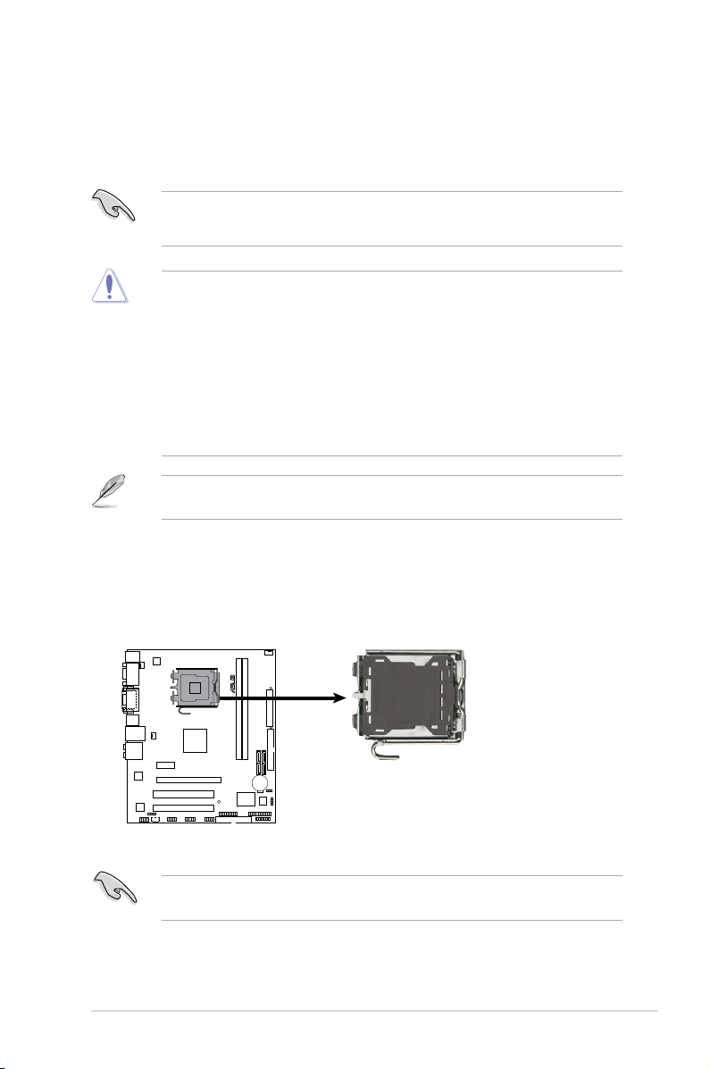
1.6.1 Installing the CPU
To install a CPU:
1. Locate the CPU socket on the motherboard.
Before installing the CPU, ensure that the box is facing towards you and the load lever is
on your left.
The motherboard supports Intel
®
LGA775 processors with the Intel
®
Enhanced Intel
SpeedStep
®
Technology (EIST) and Hyper-Threading Technology.
P5N73-CM CPU
Socket 775
R
P5N73-CM
1-8 Chapter 1: Product introduction
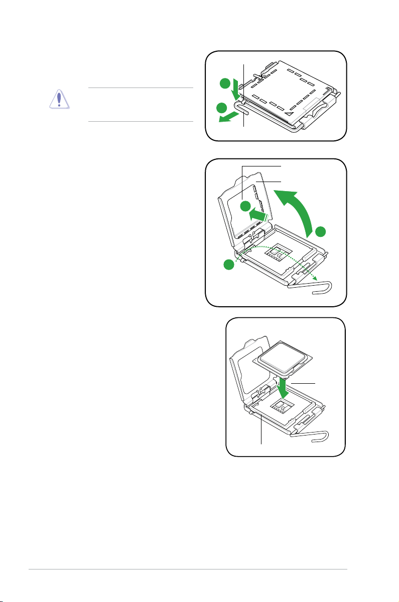
To prevent damage to the socket
pins, do not remove the PnP cap
unless you are installing a CPU.
2. Press the load lever with your thumb
(A), then move it to the left (B) until it is
released from the retention tab.
4. Lift the load plate with your thumb and
forenger to a 100º angle (4A), then
push the PnP cap from the load plate
window to remove (4B).
3. Lift the load lever in the direction of the
arrow to a 135º angle.
5. Position the CPU over the socket, ensuring
that the gold triangle is on the bottom-left
corner of the socket then t the socket
alignment key into the CPU notch.
A
B
Load lever
Retention tab
Load plate
PnP cap
4A
4B
3
Gold
triangle
mark
Alignment key
CPU notch
ASUS P5N73-CM 1-9
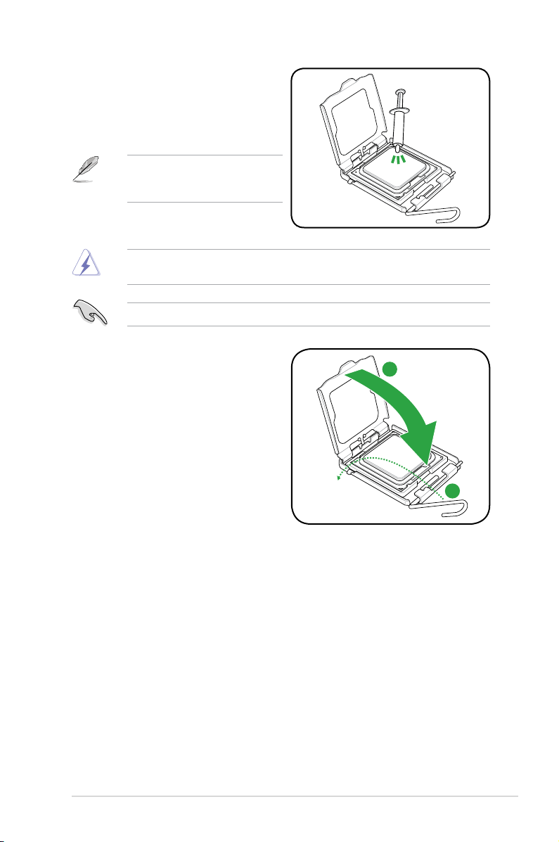
6. Apply some Thermal Interface Material
to the exposed area of the CPU that the
heatsink will be in contact with, ensuring
that it is spread in an even thin layer.
DO NOT eat the Thermal Interface Material. If it gets into your eyes or touches your skin,
ensure that you wash it off immediately, and seek professional medical help.
Some heatsinks come with
pre-applied thermal paste. If so, skip
this step.
To prevent contaminating the paste, DO NOT spread the paste with your nger directly.
7. Close the load plate (A), then push
the load lever (B) until it snaps into the
retention tab.
A
B
1-10 Chapter 1: Product introduction
1.6.2 Installing the CPU heatsink and fan
The Intel
®
LGA775 processor requires a specially designed heatsink and fan assembly to
ensure optimum thermal condition and performance.
•
When you buy a boxed Intel
®
processor, the package includes the CPU fan and
heatsink assembly. If you buy a CPU separately, ensure that you use only Intel
®
-certied
multi-directional heatsink and fan.
• Your Intel
®
LGA775 heatsink and fan assembly comes in a push-pin design and requires
no tool to install.
• If you purchased a separate CPU heatsink and fan assembly, ensure that you have
properly applied Thermal Interface Material to the CPU heatsink or CPU before you
install the heatsink and fan assembly.
Ensure that you have installed the motherboard to the chassis before you install the CPU
fan and heatsink assembly.
The type of CPU heatsink and fan assembly may differ, but the installation steps and
functions should remain the same. The illustration above is for reference only.
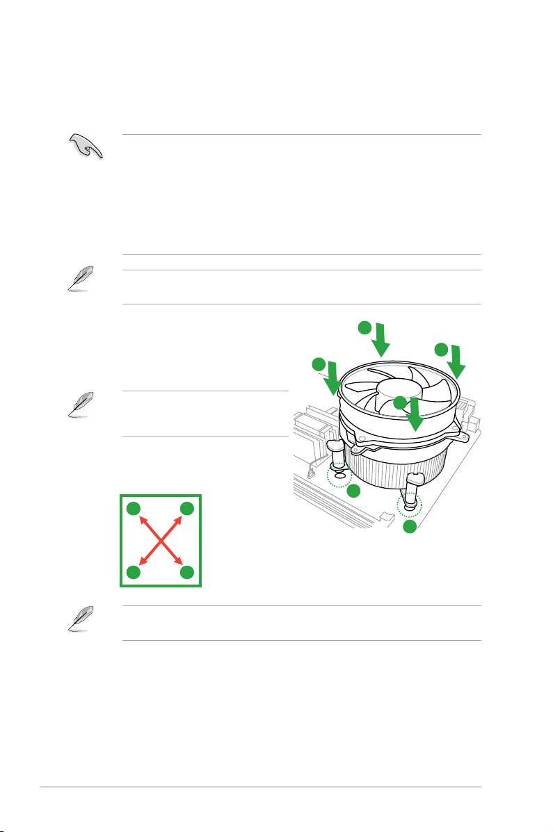
To install the CPU heatsink and fan:
1. Place the heatsink on top of the installed
CPU, ensuring that the four fasteners
match the holes on the motherboard.
2. Push down two fasteners at a time in a
diagonal sequence to secure the heatsink
and fan assembly in place.
Orient the heatsink and fan assembly
such that the CPU fan cable is closest to
the CPU fan connector.
A
A
B
B
1
1
A
B
B
A
Loading...