


P5VDC-TVM SE
Motherboard

E2827
First Edition
September 2006
Copyright © 2006 ASUSTeK COMPUTER INC. All Rights Reserved.
No part of this manual, including the products and software described in it, may be reproduced, transmitted, transcribed, stored in a retrieval system, or translated into any language in any form or by any means, except documentation kept by the purchaser for backup purposes, without the express written permission of ASUSTeK COMPUTER INC. (“ASUS”).
Product warranty or service will not be extended if: (1) the product is repaired, modified or altered, unless such repair, modification of alteration is authorized in writing byASUS; or (2) the serial number of the product is defaced or missing.
ASUS PROVIDES THIS MANUAL “AS IS” WITHOUT WARRANTY OF ANY KIND, EITHER EXPRESS OR IMPLIED, INCLUDING BUT NOT LIMITED TO THE IMPLIED WARRANTIES OR CONDITIONS OF MERCHANTABILITY OR FITNESS FOR A PARTICULAR PURPOSE. IN NO EVENT SHALL ASUS, ITS DIRECTORS, OFFICERS, EMPLOYEES OR AGENTS BE LIABLE FOR ANY INDIRECT, SPECIAL, INCIDENTAL, OR CONSEQUENTIAL DAMAGES (INCLUDING DAMAGES FOR LOSS OF PROFITS, LOSS OF BUSINESS, LOSS OF USE OR DATA, INTERRUPTION OF BUSINESS AND THE LIKE), EVEN IF ASUS HAS BEEN ADVISED OF THE POSSIBILITY OF SUCH DAMAGES ARISING FROM ANY DEFECT OR ERROR IN THIS MANUAL OR PRODUCT.
SPECIFICATIONS AND INFORMATION CONTAINED IN THIS MANUAL ARE FURNISHED FOR INFORMATIONAL USE ONLY, AND ARE SUBJECT TO CHANGE AT ANY TIME WITHOUT NOTICE, AND SHOULD NOT BE CONSTRUED AS A COMMITMENT BY ASUS. ASUS ASSUMES NO RESPONSIBILITY OR LIABILITY FOR ANY ERRORS OR INACCURACIES THAT MAY APPEAR IN THIS MANUAL, INCLUDING THE PRODUCTS AND SOFTWARE DESCRIBED IN IT.
Products and corporate names appearing in this manual may or may not be registered trademarks or copyrights of their respective companies, and are used only for identification or explanation and to the owners’ benefit, without intent to infringe.
ii

Contents
Notices........................................................................................................ |
vii |
Safety information..................................................................................... |
viii |
About this guide.......................................................................................... |
ix |
P5VDC-TVM SE specifications summary.................................................. |
xi |
Chapter 1: Product introduction
1.1 |
Special features............................................................................ |
1-2 |
|
1.2 |
Before you proceed...................................................................... |
1-4 |
|
1.3 |
Motherboard overview................................................................. |
1-5 |
|
|
1.3.1 |
Placement direction ......................................................... |
1-5 |
|
1.3.2 |
Screw holes ..................................................................... |
1-5 |
|
1.3.3 |
Motherboard layout .......................................................... |
1-6 |
1.4 |
Central Processing Unit (CPU).................................................... |
1-7 |
|
|
1.4.1 |
Installling the CPU ........................................................... |
1-7 |
|
1.4.2 |
Installling the CPU heatsink and fan .............................. |
1-10 |
|
1.4.3 |
Uninstalling the CPU heatsink and fan .......................... |
1-12 |
1.5 |
System memory.......................................................................... |
1-14 |
|
|
1.5.1 |
Overview ........................................................................ |
1-14 |
|
1.5.2 |
Memory Configurations ................................................ |
1-14 |
|
1.5.3 |
Installing a DDR DIMM (black slots) .............................. |
1-15 |
|
1.5.4 |
Removing a DDR DIMM ................................................ |
1-15 |
|
1.5.5 |
Installing a DDR2 DIMM (yellow slots) . ......................... |
1-16 |
|
1.5.6 |
Removing a DDR2 DIMM .............................................. |
1-16 |
1.6 |
Expansion slots.......................................................................... |
1-20 |
|
|
1.6.1 |
Installing an expansion card .......................................... |
1-17 |
|
1.6.2 |
Configuring an expansion card ...................................... |
1-17 |
|
1.6.3 |
Interrupt assignments .................................................... |
1-18 |
|
1.6.4 |
PCI slots . ....................................................................... |
1-19 |
|
1.6.5 |
PCI Express x1 slot . ...................................................... |
1-19 |
|
1.6.6 |
PCI Express x16 slot . .................................................... |
1-19 |
1.7 |
Jumpers |
....................................................................................... |
1-20 |
1.8 |
Connectors.................................................................................. |
1-22 |
|
|
1.8.1 .................................................. |
Rear panel connectors |
1-22 |
|
1.8.2 ........................................................ |
Internal connectors |
1-23 |
iii

Contents
Chapter 2: BIOS setup
2.1 |
BIOS setup program..................................................................... |
2-2 |
|
2.2 |
BIOS menu screen........................................................................ |
2-3 |
|
|
2.2.1 |
Legend Box..................................................................... |
2-3 |
|
2.2.2 |
List Box............................................................................ |
2-4 |
|
2.2.3 |
Sub-menu........................................................................ |
2-4 |
2.3 |
Standard BIOS Features.............................................................. |
2-5 |
|
|
2.3.1 |
Date [Day, xx/xx/xxxx]...................................................... |
2-5 |
|
2.3.2 |
Time [xx:xx:xxxx]............................................................. |
2-5 |
|
2.3.3 |
IDE Channel 0/1 Master/Slave........................................ |
2-5 |
|
2.3.4 |
SATAChannel 2/3 Master................................................ |
2-7 |
|
2.3.5 |
DriveA[1.44M, 3.5 in.].................................................... |
2-8 |
|
2.3.6 |
Video [EGA/VGA]............................................................ |
2-8 |
|
2.3.7 |
Halt On [All, But Keyboard].............................................. |
2-8 |
|
2.3.8 |
Base Memory/Extended Memory/Total Memory [xxxK]... |
2-8 |
2.4 |
Advanced BIOS Features............................................................. |
2-9 |
|
|
2.4.1 |
CPU Feature [Press Enter].............................................. |
2-9 |
|
2.4.2 |
Hard Disk Boot Priority [Press Enter]............................ |
2-10 |
|
2.4.3 |
Quick Power On Self Test [Enabled].............................. |
2-10 |
|
2.4.4 |
First/Second/Third Boot Device..................................... |
2-10 |
|
2.4.5 |
Boot Other Device [Enabled]......................................... |
2-10 |
|
2.4.6 |
Boot Up Floppy Seek [Disabled]..................................... |
2-11 |
|
2.4.7 |
Boot Up NumLock [On]................................................... |
2-11 |
|
2.4.8 |
Security Option [Setup]................................................... |
2-11 |
|
2.4.9 |
OS Select For DRAM > 64MB [Non-OS2]...................... |
2-11 |
|
2.4.10 |
HDD S.M.A.R.T. Capability [Disabled]............................ |
2-11 |
|
2.4.11 |
Small Logo (EPA) Show [Enabled]................................. |
2-11 |
|
2.4.12 |
Video BIOS Shadow [Disabled]...................................... |
2-11 |
2.5 |
Advanced Chipset Features...................................................... |
2-12 |
|
|
2.5.1 |
Current FSB Frequency [200MHz]................................ |
2-12 |
|
2.5.2 |
Current DRAM Frequency [200MHz]............................. |
2-12 |
|
2.5.3 |
DRAM Frequency [Auto]................................................ |
2-12 |
|
2.5.4 |
DRAM Timing Selectable [By SPD]............................... |
2-13 |
|
2.5.5 |
Memory Hole [Disabled]................................................ |
2-13 |
iv
Contents
|
2.5.6 |
Primary DisplayAdapter [PCi_E]................................... |
2-13 |
|
2.5.7 |
VGAShare Memory Size [64MB].................................. |
2-13 |
2.6 |
Integrated Peripherals................................................................ |
2-14 |
|
|
2.6.1 |
Onchip IDE Device [Press Enter].................................. |
2-14 |
|
2.6.2 |
Onboard Device [Press Enter]....................................... |
2-15 |
|
2.6.3 |
Super IO Device [Press Enter]...................................... |
2-16 |
2.7 |
Power Management Setup......................................................... |
2-17 |
|
|
2.7.1 |
ACPI Function [Enabled]............................................... |
2-17 |
|
2.7.2 |
ACPI Suspend Type [S3(STR)]..................................... |
2-17 |
|
2.7.3 |
Off by Power Button [Instant-Off]................................... |
2-18 |
|
2.7.4 |
Resume by PCI PME [Disabled].................................... |
2-18 |
|
2.7.5 |
Resume by Ring [Disabled]........................................... |
2-18 |
|
2.7.6 |
Resume by USB (S3) [Enabled].................................... |
2-18 |
|
2.7.7 |
Resume by PCI-E Device [Disabled]............................. |
2-18 |
|
2.7.8 |
Resume byAlarm [Diabled]........................................... |
2-18 |
|
2.7.9 |
Day (of Month)Alarm [0]................................................ |
2-18 |
|
2.7.10 |
Time (hh:mm:ss)Alarm [0:0:0]....................................... |
2-18 |
|
2.7.11 |
Power On By Mouse [Disabled]..................................... |
2-19 |
|
2.7.12 |
Power On By Keyboard [Disabled]................................ |
2-19 |
|
2.7.13 |
StateAfter Power Failure [Off]....................................... |
2-19 |
2.8 |
PnP/PCI Configurations............................................................. |
2-20 |
|
|
2.8.1 |
PNP OS Installed [No]................................................... |
2-20 |
|
2.8.2 |
Reset Configuration Date [Disabled]............................. |
2-20 |
|
2.8.3 |
Resources controlled By [Auto(ESCD)]......................... |
2-20 |
|
2.8.4 |
IRQ Resources [Press Enter]........................................ |
2-21 |
|
2.8.5 |
PCI/VGAPalette Snoop [Disabled]................................ |
2-21 |
|
2.8.6 |
Assign IRQ For VGA[Enabled]..................................... |
2-21 |
|
2.8.7 |
Assign IRQ For USB [Enabled]..................................... |
2-21 |
|
2.8.8 |
INT Pin xAssignment [Auto].......................................... |
2-21 |
|
2.8.9 |
PCI Express relative items............................................ |
2-22 |
|
2.8.10 |
maximum Payload Size [4096]...................................... |
2-22 |
2.9 |
PC Health Status......................................................................... |
2-22 |
|
|
2.9.1 |
CPU Temperature, MB Temperature............................. |
2-22 |
|
2.9.2 |
CPU Fan Speed, System Fan Speed............................ |
2-22 |
|
|
|
|

Contents
|
2.9.3 |
VCORE Voltage, 3.3 Voltage, +5V in, +12V in.............. |
2-22 |
|
2.9.4 |
CPU Fan Speed warning [800RPM].............................. |
2-23 |
|
2.9.5 |
CPU FAN SPEED CONTROL [Enabled]....................... |
2-23 |
|
2.9.6 |
Start Up Temperature (°C) [50]...................................... |
2-23 |
|
2.9.7 |
Full Speed Temperature (°C) [70].................................. |
2-23 |
|
2.9.8 |
Start Up PWM [60]......................................................... |
2-23 |
|
2.9.9 |
Slope Select PWM/C [4 PWM/°C]................................. |
2-23 |
2.10 |
Frequency/Voltage Control........................................................ |
2-24 |
|
|
2.10.1 |
Spread Spectrum [Enabled].......................................... |
2-24 |
2.11 |
Other Items.................................................................................. |
2-25 |
|
|
2.11.1 |
Load Fail-safe Defaults.................................................. |
2-25 |
|
2.11.2 |
Load Optimized Defaults............................................... |
2-25 |
|
2.11.3 |
Set Supervisor Password.............................................. |
2-25 |
|
2.11.4 |
Set User Password........................................................ |
2-25 |
|
2.11.5 |
Save & Exit Setup.......................................................... |
2-25 |
|
2.11.6 |
Exit Without Saving....................................................... |
2-25 |
vi

Notices
Federal Communications Commission Statement
This device complies with Part 15 of the FCC Rules. Operation is subject to the following two conditions:
•This device may not cause harmful interference, and
•This device must accept any interference received including interference that may cause undesired operation.
This equipment has been tested and found to comply with the limits for a
Class B digital device, pursuant to Part 15 of the FCC Rules. These limits are designed to provide reasonable protection against harmful interference in a residential installation. This equipment generates, uses and can radiate radio frequency energy and, if not installed and used in accordance with manufacturer’s instructions, may cause harmful interference to radio communications. However, there is no guarantee that interference will not occur in a particular installation. If this equipment does cause harmful interference to radio or television reception, which can be determined by turning the equipment off and on, the user is encouraged to try to correct the interference by one or more of the following measures:
•Reorient or relocate the receiving antenna.
•Increase the separation between the equipment and receiver.
•Connect the equipment to an outlet on a circuit different from that to which the receiver is connected.
•Consult the dealer or an experienced radio/TV technician for help.
The use of shielded cables for connection of the monitor to the graphics card is required to assure compliance with FCC regulations. Changes or modifications to this unit not expressly approved by the party responsible for compliance could void the user’s authority to operate this equipment.
Canadian Department of Communications Statement
This digital apparatus does not exceed the Class B limits for radio noise emissions from digital apparatus set out in the Radio Interference Regulations of the Canadian Department of Communications.
This class B digital apparatus complies with Canadian
ICES-003.
vii

Safety information
Electrical safety
•To prevent electrical shock hazard, disconnect the power cable from the electrical outlet before relocating the system.
•When adding or removing devices to or from the system, ensure that the power cables for the devices are unplugged before the signal cables are connected. If possible, disconnect all power cables from the existing system before you add a device.
•Before connecting or removing signal cables from the motherboard, ensure that all power cables are unplugged.
•Seek professional assistance before using an adapter or extension cord. These devices could interrupt the grounding circuit.
•Make sure that your power supply is set to the correct voltage in your area. If you are not sure about the voltage of the electrical outlet you are using, contact your local power company.
•If the power supply is broken, do not try to fix it by yourself. Contact a qualified service technician or your retailer.
Operation safety
•Before installing the motherboard and adding devices on it, carefully read all the manuals that came with the package.
•Before using the product, make sure all cables are correctly connected and the power cables are not damaged. If you detect any damage, contact your dealer immediately.
•To avoid short circuits, keep paper clips, screws, and staples away from connectors, slots, sockets and circuitry.
•Avoid dust, humidity, and temperature extremes. Do not place the product in any area where it may become wet.
•Place the product on a stable surface.
•If you encounter technical problems with the product, contact a qualified service technician or your retailer.
This symbol of the crossed out wheeled bin indicates that the product (electrical and electronic equipment) should not be placed in municipal waste.
Please check local regulations for disposal of electronic products.
viii

About this guide
This user guide contains the information you need when installing and configuring the motherboard.
How this guide is organized
This manual contains the following parts:
•Chapter 1: Product introduction
This chapter describes the features of the motherboard and the new technology it supports. This chapter also lists the hardware setup procedures that you have to perform when installing system components. It includes description of the jumpers and connectors on the motherboard.
•Chapter 2: BIOS setup
This chapter tells how to change system settings through the BIOS Setup menus. Detailed descriptions of the BIOS parameters are also provided.
Where to find more information
Refer to the following sources for additional information and for product and software updates.
1.System builder websites
The system builder website provides updated information on hardware and software products. Refer to the contact information.
2.Optional documentation
Your product package may include optional documentation, such as warranty flyers, that may have been added by your dealer. These documents are not part of the standard package.
ix

Conventions used in this guide
To make sure that you perform certain tasks properly, take note of the following symbols used throughout this manual.
DANGER/WARNING: Information to prevent injury to yourself when trying to complete a task.
CAUTION: Information to prevent damage to the components when trying to complete a task.
IMPORTANT: Instructions that you MUST follow to complete a task.
NOTE: Tips and additional information to help you complete a task.
Typography
Bold text |
Indicates a menu or an item to select. |
Italics |
Used to emphasize a word or a phrase. |
<Key> |
Keys enclosed in the less-than and greater-than sign |
|
means that you must press the enclosed key. |
|
Example: <Enter> means that you must press the |
|
Enter or Return key. |
<Key1+Key2+Key3> |
If you must press two or more keys simultaneously, the |
|
key names are linked with a plus sign (+). |
|
Example: <Ctrl+Alt+D> |
Command |
Means that you must type the command exactly |
|
as shown, then supply the required item or value |
|
enclosed in brackets. |
|
Example: At the DOS prompt, type the command line: |
|
afudos /i[filename] |
|
afudos /iPSVDCTVM.ROM |
P5VDC-TVM SE specifications summary
CPU
Chipset
Front Side Bus
Memory
Expansion slots
VGA
Storage
LAN
Audio
Back panel I/O Ports
Firewire (optional)
LGA775 socket for Intel® Pentium® D/Pentium® 4/Celeron
CPU Compatible with Intel® 05A/04Aprocessors
Supports Intel® EM64T/Hyper-Threading Technology
(Note: Due to chipset limitation, the Intel Enhanced Intel
SpeedStep Technology, C1E, and TM2 are not supported in this model)
Northbridge: VIAP4M890
Southbridge: VIAVT8237R+
1066/800/533 MHz
2 x 240-pin DIMM sockets support max. 2GB DDR2 533/400 non-ECC, unbuffered memory.
2 x 184-pin DIMM sockets support max. 2GB DDR 400/333/266 non-ECC, unbuffered memory (Note:DDR and DDR2 memory can not be used
simultaneously)
1 x PCI Express™ x16
1 x PCI Express™ x1
2 x PCI, PCI 2.2
Integrated VIAUniChrome Graphics, up to 64MB shared memory
South Bridge: VT8237R+
2 x UltraDMA133/100/66
2 x SerialATA1.5Gb/s with RAID 0, 1 & JBOD function
Realtek RTL8100C 10/100 LAN controller
RealtekALC655AC’97 6-channelAudio CODEC
1 x Parallel port
1 x RJ-45
4 x USB 2.0
1 x VGA out
1 x Serial port
1 x PS/2 keyboard
1 x PS/2 mouse
1 x 6-ChannelAudio I/O
1 x IEEE 1394a port (optional)
T1 firewire
2 ports (1 on the rear panel,1 onboard)
(continued on the next page)
xi
P5VDC-TVM SE specifications summary
BIOS
Manageability
USB
Internal I/O connectors
Form Factor
4 Mb Flash ROM,AWARD BIOS, PnP, WfM2.0, DMI2.0, SM BIOS 2.3
WOL by PME, WOR by PME, PXE
Max. 8 USB 2.0 ports
2 x USB 2.0/1.1 connector supports additional 4 USB ports
2 x SATAconnector
2 x IDE connector CPU/Chassis fan connectors 24-pin EATX Power connector 4-pinATX 12 V Power connector CD/AUX audio-in connector
Chassis Intrusion (optional)
1 x Floppy disk drive connector
1 x S/PDIF out connector
Front panel audio connector
System panel connector
1 x IR connector
1 x Com port
1 x IEEE 1394a connector (optional)
mATX Form Factor, 9.6 in x 9.6 in (24.5 cm x 24.5 cm)
*Specifications are subject to change without notice.
xii
This chapter describes the motherboard features and the new technologies
it supports.
Product1 introduction
1.1Special features
Latest processor technology 
This motherboard comes with a 775-pin surface mount Land GridArray (LGA) socket designed for the Intel® Pentium® 4 processor in the 775-land package.
Supporting the Intel® Pentium® 4 processor with 1066 MHz Front Side Bus (FSB), this motherboard is equipped with Intel® Hyper Threading Technology and is fully compatible with the Intel® 05A/04Aprocessors.
See page 1-6 for details.
64-bit CPU support 
64-bit computing, the next generation technology to replace current 32-bit architecture, delivers advanced system performance, faster memory access and increased productivity. This motherboard provides excellent compatibility and flexibility by supporting either 64-bit or 32-bit architecture.
Dual-Core CPU 
Enjoy the extraordinary CPU power from the latest dual-core CPU. The advanced processing technology contains two physical CPU cores with individually dedicated
L2 cache to satisfy the rising demand for more powerful processing capability.
PCI Express™ interface 
ThemotherboardfullysupportsPCIExpress, the latest I/O interconnect technology that speeds up the PCI bus. PCI Express features point topoint serial interconnections between devices and allows higher clockspeeds by carrying data in packets. This high speed interface is software compatible with existing PCI specifications. See page 1-19 for details.
Serial ATA I technology 
The motherboard supports the Serial ATA I technology through the Serial ATA interfaces and the VIAVT8237R+ chipset. The SATAspecification allows for thinner, more flexible cables with lower pin count, reduced voltage requirement, and up to 300 MB/s data transfer rate. See page 1-25 for details.
Onboard RAID solution
The onboard VIAVT8237R+ chipset allows RAID 0, RAID 1 and JBOD configuration for four SATAconnectors.
1- |
Chapter 1: Product introduction |
USB 2.0 technology 
The motherboard implements the Universal Serial Bus (USB) 2.0 specification, dramatically increasing the connection speed from the 12 Mbps bandwidth on USB 1.1 to a fast 480 Mbps on USB 2.0. USB 2.0 is backward compatible with USB 1.1. See page 1-23 and 1-28 for details.
AUDIO CODEC
The RealtekALC655 is anAC”97 CODEC that allows 6-channel audio playback.
The audio CODEC provides six DAC channels for 5.1 surround sound, AUX, and Line In stereo inputs.
ASUS P5VDC-TVM SE |
1- |
1.2Before you proceed
Take note of the following precautions before you install motherboard components or change any motherboard settings.
•Unplug the power cord from the wall socket before touching any component.
•Use a grounded wrist strap or touch a safely grounded object or to a metal object, such as the power supply case, before handling components to avoid damaging them due to static electricity
•Hold components by the edges to avoid touching the ICs on them.
•Whenever you uninstall any component, place it on a grounded antistatic pad or in the bag that came with the component.
•Before you install or remove any component, ensure that the ATX power supply is switched off or the power cord is detached from the power supply. Failure to do so may cause severe damage to the motherboard, peripherals, and/or components.
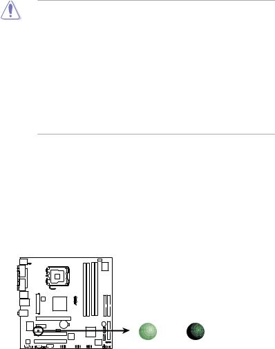
Onboard LED
The motherboard comes with a standby power LED that lights up to indicate that the system is ON, in sleep mode, or in soft-off mode. This is a reminder that you should shut down the system and unplug the power cable before removing or plugging in any motherboard component. The illustration below shows the location of the onboard LED.
P5VDC-TVM SE |
SB_PWR1 |
|
|
||
|
ON |
OFF |
P5VDC-TVM SE Onboard LED |
Standby |
Powered |
Power |
Off |
|
1- |
Chapter 1: Product introduction |

1.3Motherboard overview
Before you install the motherboard, study the configuration of your chassis to ensure that the motherboard fits into it.
Make sure to unplug the power cord before installing or removing the motherboard. Failure to do so can cause you physical injury and damage motherboard components.
1.3.1Placement direction
When installing the motherboard, make sure that you place it into the chassis in the correct orientation. The edge with external ports goes to the rear part of the chassis as indicated in the image below.
1.3.2Screw holes
Place eight (8) screws into the holes indicated by circles to secure the motherboard to the chassis.
Do not overtighten the screws! Doing so can damage the motherboard.
Place this side towards the rear of the chassis
P5VDC-TVM SE |
ASUS P5VDC-TVM SE |
1- |

1.3.3Motherboard layout
|
|
|
24.5cm (9.6in) |
|
PS/2KBMS |
|
|
|
|
T: Mouse |
KBPWR1 |
|
|
|
B: Keyboard |
|
|
|
|
COM1 |
|
|
|
|
PARALLEL PORT |
|
|
LGA775 |
|
|
|
|
|
|
VGA1 |
|
|
|
SE |
|
|
|
|
|
F_USB12 |
ATXPWR1 |
|
|
TVM-P5VDC |
LAN_USB34 |
|
® |
||
|
ATX12V1 |
VIA |
|
|
|
|
|
P4M890 |
|
Top:Line In |
|
|
|
|
Center:Line Out |
|
|
|
|
Below:Mic In |
|
|
|
|
PCIEX16
TL8100CR |
|
|
|
|
|
|
CR2032 3V |
|
|
|
|
|
|
|
|
Lithium Cell |
|
||
|
|
|
PCIEX1 |
|
|
|
CMOS Power |
|
|
|
|
|
|
|
|
|
|
||
|
|
|
|
|
|
|
CHA_FAN1 |
|
|
|
|
|
SB_PWR1 |
|
|
|
|||
|
|
|
|
|
|
||||
|
|
|
|
|
|
|
|
||
|
|
|
|
|
|
|
|
|
|
|
|
|
|
|
PCI1 |
|
|||
|
ALC655 |
|
PCI2 |
|
|
|
|
|
|
|
|
AUX1 |
AAFP1 |
CD1 |
COM2 |
IE1394_1 |
USB56 |
|
|
SPDIF_OUT1 |
|
|
|
|
|
|
|
|

 CPU_FAN1
|
|
|
Super |
|
|
|
|
|
|
|
I/O |
|
|
|
|
|
|
CHASSIS1 |
|
|
DDR2_A1 (64 bit,240-pin module) DDR2_B1 (64 bit,240-pin module) |
DDR_A1 (64 bit,240-pin module) |
DDR_B1 (64 bit,240-pin module) |
|
PRI_IDE1 |
SEC_IDE1 |
(9.6in) |
|
|
|
|
|
|
24.5cm |
|
|
BUZZER1 |
|
|
|
|
|
|
SATA2 |
|
|
|
|
|
VIA |
|
|
|
|
|
VT8237R+ |
|
|
FLOPPY1 |
|
||
|
|
SATA1 |
|
|
||
|
|
|
|
|
||
USB78 |
4Mb |
CLRTC1 |
|
IR_CON1 |
|
|
BIOS |
|
F_PANEL1 |
|
|||
|
|
|
|
|
|
|
1- |
Chapter 1: Product introduction |
1.4Central Processing Unit (CPU)
The motherboard comes with a surface mount LGA775 socket designed for the Intel® Pentium® 4/Intel® Pentium® D processor in the 775-land package.
•Your boxed Intel® Pentium® 4 LGA775 processor package should
come with installation instructions for the CPU, fan and heatsink assembly. If the instructions in this section do not match the CPU documentation, follow the latter.
•Upon purchase of the motherboard, make sure that the PnP cap is on the socket and the socket pins are not bent. Contact your retailer immediately if the PnP cap is missing, or if you see any damage to the PnP cap/socket pins/motherboard components.ASUS will shoulder the cost of repair only if the damage is shipment/transit-related.
•Keep the cap after installing the motherboard. ASUS will process Return
MerchandiseAuthorization (RMA) requests only if the motherboard comes with the cap on the LGA775 socket.
•The product warranty does not cover damage to the socket pins resulting from incorrect CPU installation/removal, or misplacement/loss/incorrect removal of the PnP cap.
• Due to chipset limitation.The motherboard does not support Enhanced
Intel SpeedStep technology, C1E and TM2 technology.
•This motherboard does not support Intel® Pentium® Processor Extreme Edition.
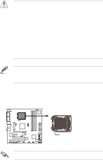
1.4.1Installling the CPU
To install a CPU:
1.Locate the CPU socket on the motherboard.
P5VDC-TVM SE |
P5VDC-TVM SE CPU Socket 775
Before installing the CPU, make sure that the socket box is facing towards you and the load lever is on your left.
ASUS P5VDC-TVM SE |
1- |
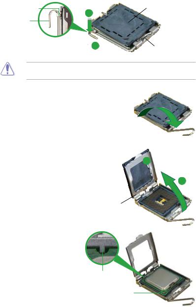
2.Press the load lever with your thumb (A) and move it to the left (B) until it is released from the retention tab.
Retention tab |
PnP Cap |
Load lever |
A |
|
B
This side of the cam box should face you.
To prevent damage to the socket pins, do not remove the PnP cap unless you are installing a CPU.
3.Lift the load lever in the direction of the arrow to a 135º angle.
4.Lift the load plate with your thumb and forefinger to a 100º angle (A), then push the PnP cap from the load plate window to remove (B).
B
A
Load plate
5.Position the CPU over the socket, making sure that the gold triangle is on the bottom left corner of the socket. The socket
alignment key should fit into the CPU notch.
Alignment key
Gold triangle mark
1- |
Chapter 1: Product introduction |
6. Close the load plate (A), then push A the load lever (B) until it snaps into
the retention tab.
B
The CPU fits in only one correct orientation. DO NOT force the CPU into the socket to prevent bending the connectors on the socket and damaging the CPU!
Notes on Intel® Hyper-Threading Technology
•This motherboard supports Intel® Pentium® 4 CPUs in the 775-land package with Hyper Threading Technology.
•Hyper-Threading Technology is supported under Windows® XP/2003 Server and Linux 1.7.x (kernel) and later versions only. Under Linux, use the Hyper-Threading compiler to compile the code. If you are using any other operating systems, disable the Hyper-Threading Technology item in the BIOS to ensure system stability and performance.
•Installing Windows® XP Service Pack 1 or later version is recommended.
•Make sure to enable the Hyper-Threading Technology item in BIOS before installing a supported operating system.
•For more information on Hyper-Threading Technology, visit www.intel. com/info/hyperthreading.
To use the Hyper-Threading Technology on this motherboard:
1.Install an Intel® Pentium® 4 CPU in the 775-land package that supports
Hyper-Threading Technology.
2.Power up the system and enter the BIOS Setup (see Chapter 2: BIOS setup). Under the Advanced Menu, make sure that the item Hyper Threading Technology is set to Enabled. The item appears only if you installed a CPU that supports Hyper-Threading Technology.
3.Reboot the computer.
ASUS P5VDC-TVM SE |
1- |
 Loading...