


English
P6 Series
ASUS PC (Desktop Barebone)
Installation manual
A6359_P6 QSG.indb 1 |
|
|
2/16/11 5:43:02 PM |
|
|

English
Front panel features
1 |
3 |
1 |
3 |
4
5
6
2
7
1.Power button. Press this button to turn the system on.
2.Front panel cover. Push  to open the front panel cover.
3.Optical disk drive cover. Push 
 to eject the optical disk tray.
4.Microphone port. This Mic (pink) port connects a microphone.
5.Headphone port. This Line out (lime) port connects a headphone with a stereo mini-plug.
6.USB 2.0 / USB 3.0 ports. These Universal Serial Bus 2.0 / These Universal Serial Bus 3.0 (USB 2.0 / USB 3.0) ports are available for connecting USB
2.0 / USB 3.0 devices such as a mouse, printer, scanner, camera, PDA, and others.
7.Multimedia Card / Secure Digital™ / MemoryStick® / Memory Stick Pro™ card slot
|
Installation manual |
A6359_P6 QSG.indb 2 |
|
|
2/16/11 5:43:04 PM |
|
|

Rear panel features
1. |
Chassis air vent. |
|
2 |
||
2. |
Power supply unit fan vent. |
1 |
|||
3. |
Chassis fan vent. |
|
|||
|
|
Do NOT cover the rear vent , and the ambient |
|
4 |
|
|
|
|
|
||
|
|
temperature is limited up to 35oC to prevent the |
|
|
|
|
|
system from overheating. |
|
|
|
4. |
Power connector. |
3 |
5 |
||
5. |
One of the following audio ports configurations: |
||||
|
|||||
|
|
|
|
9 |
|
|
• |
6-channel |
|
|
|
• 8-channel
Refer to the configuration table in the User Guide for details.
6.LAN (RJ-45) port (


 )
)
7.USB 2.0 / USB 3.0 ports (  )
)
8.VGA port ( )
)
9.One of the following ports:
•E-SATA port (


 )
)
•Serial (COM1) port ( )
)
• |
DVI port ( |
) |
• |
HDMI port ( |
) |
English
Installation manual |
|
A6359_P6 QSG.indb 3 |
|
|
2/16/11 5:43:10 PM |
|
|

Internal components |
|
|
English |
4 |
|
|
|
|
2 |
|
|
1 |
3 |
|
|
|
|
5 |
5 |
|
|
6 |
7 |
|
|
1. |
Front panel cover |
5. |
ASUS motherboard* |
2. |
5.25-inch optical drive bays |
6. |
Expansion slot metal brackets |
3. |
Hard disk drive bay |
7. |
Metal bracket lock |
4.Power supply unit (under the HDD bay)
NOTE: *Refer to the system User Guide for motherboard details.
|
Installation manual |
A6359_P6 QSG.indb 4 |
|
|
2/16/11 5:43:11 PM |
|
|

Removing the side cover and front panel assembly
1.Remove the cover screws on the rear panel.
2.Pull the side cover toward the rear panel until its hooks disengage from the chassis tab holes. Set the side cover aside.
3.Locate the front panel assembly hooks, then lift them until they disengage from the chassis.
4.Swing the front panel assembly to the left, until the hinge-like tabs on the right side of the assembly are exposed.
5.Remove the front panel assembly, then set aside.
4 |
3 |
1 |
|
|
|
3 |
2 |
|
4 |
1 |
||
|
4 |
3 |
Air duct |
|
|
|
4 |
|
3 |
4 |
2 |
|
|
|
Chassis tab holes |
4
English
Installation manual |
|
A6359_P6 QSG.indb 5 |
|
|
2/16/11 5:43:12 PM |
|
|
English
Installing a CPU
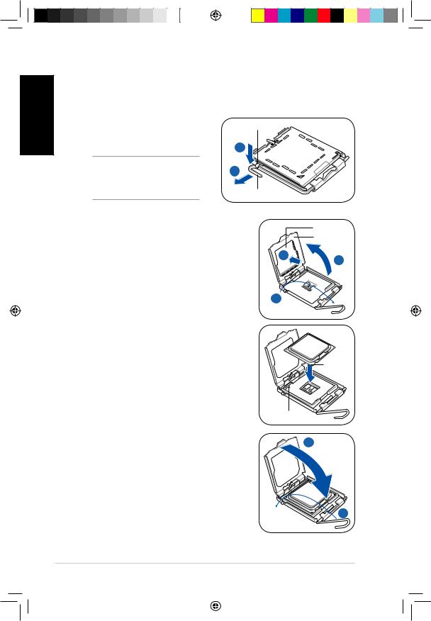
Installing an Intel® CPU in the LGA775 package
1.Locate the CPU socket on the motherboard.
2. Press the load lever with your thumb |
Retention tab |
(A), then move it to the left (B) until it |
|
is released from the retention tab. |
A |
|
|
CAUTION! To prevent damage to |
B |
the socket pins, do not remove the |
|
PnP cap unless you are installing |
|
a CPU. |
Load lever |
|
3.Lift the load lever in the direction of the arrow to a 135º angle.
4.Lift the load plate with your thumb and forefinger to a 100º angle (4A), then push the
PnP cap from the load plate window to remove (4B).
5.Position the CPU over the socket, making sure that the gold triangle is on the bottom left corner of the socket. Fit the socket alignment key into the CPU notch.
|
PnP cap |
|
Load plate |
4B |
4A |
|
3 


Gold triangle mark
|
|
Alignment key |
6. |
Close the load plate (A), then push the load |
A |
|
lever (B) until it snaps into the retention tab. |
B
Installation manual
A6359_P6 QSG.indb 6 |
|
|
2/16/11 5:43:14 PM |
|
|

Installing an Intel® CPU in the LGA1156 package
1.Locate the CPU socket on the motherboard.
2.Press the load lever with your thumb (A), and then move it to the right (B) until it is released from the retention tab.
CAUTION! To prevent damage to the socket pins, do not remove the PnP cap unless you are installing a CPU.
3.Lift the load lever in the direction of the arrow until the load plate is completely lifted.
4.Remove the PnP cap from the CPU socket by lifting the tab only.
5.Position the CPU over the socket, ensuring that the gold triangle is on the bottom left corner of the socket, and then fit the socket alignment keys into the CPU notches.
Load lever
B
Retention tab
 3
3
Load plate |
4 |
|
PnP cap |
||
|
Cap tab
CPU notches
Gold |
triangle |
mark |
Alignment keys |
6. Close the load plate (A), and then push down |
B |
the load lever (B), ensuring that the front edge |
|
of the load plate slides under the retention lock |
|
(C). |
A |
English
Installation manual |
|
A6359_P6 QSG.indb 7 |
|
|
2/16/11 5:43:16 PM |
|
|
7.Insert the load lever under the retention tab.
English
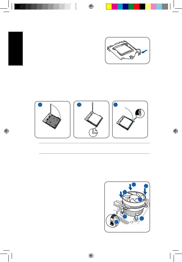
Installing an AMD CPU
1.Locate the CPU socket, then lift the socket lever to a 90º angle.
2.Install the CPU to the socket, making sure that the CPU corner with the gold triangle matches the socket corner with a small triangle.
3.Push down the socket lever to secure the CPU.
1 |
2 |
3 |
CAUTION: Incorrect installation of the CPU into the socket may bend the pins and severely damage the CPU!
Installing the CPU fan and heatsink assembly
Installing an Intel® CPU heatsink and fan
1.Place the heatsink on top of the installed CPU, making sure that the four fasteners match the holes on the motherboard.
2.Push down two fasteners at a time in a diagonal sequence to secure the heatsink and fan assembly in place.
3.When the fan and heatsink assembly is in place, connect the CPU fan cable to the connector on the motherboard.
2 2
2
 2
2
|
1 |
1 |
3 |
|
|
|
|
|
Installation manual |
A6359_P6 QSG.indb 8 |
|
|
2/16/11 5:43:19 PM |
|
|
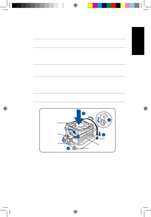
Installing an AMD CPU heatsink and fan |
|
|
||
1. |
Place the heatsink on top of the installed CPU. |
|
English |
|
|
IMPORTANT. Make sure that the fan and heatsink assembly perfectly fits the retention |
|||
|
mechanism module base; otherwise you can not lock the retention bracket. |
|
||
2. |
Attach one end of the retention bracket to the retention module base. |
|
||
3. |
Attach the other end of the retention bracket (near the retention bracket lock) |
|
||
|
to the retention module base until it clicks in place. |
|
||
|
NOTE. Your boxed CPU should come with installation instructions for the CPU, fan/heatsink |
|
||
|
assembly, and the retention mechanism. If the instructions in this section do not match the |
|
||
|
CPU documentation, follow the latter. |
|
|
|
4. |
Push down the retention bracket lock on the retention mechanism to secure |
|
||
|
the fan and heatsink to the module retention module base. |
|
||
5. |
Connect the CPU fan cable to the connector on the motherboard. |
|
||
|
CAUTION: Do not forget to connect the CPU fan connector! Hardware monitoring error |
|
||
|
can occur if you fail to plug this connector. |
|
|
|
|
|
1 |
|
|
|
CPU fan |
|
2 |
|
|
|
|
|
|
|
Retention |
|
5 |
|
|
bracket lock |
4 |
|
|
|
|
CPU fan |
|
|
|
|
|
|
|
|
Retention bracket |
|
connector |
|
|
|
CPU heatsink |
|
|
|
3 |
|
|
|
|
|
Retention module base |
|
|
Installation manual |
|
A6359_P6 QSG.indb 9 |
|
|
2/16/11 5:43:20 PM |
|
|

English
Installing a DIMM
1.Locate the DIMM sockets in the motherboard.
2.Unlock a DIMM socket by pressing the retaining clips outward.
3.Align a DIMM on the socket such that the notch on the DIMM matches the break on the socket.
4.Push the DIMM to the socket until the retaining clips snap inward.
4 |
4 |
4


 2 2
2 2
 3
3
CAUTION:
•Unplug the power supply before adding or removing DIMMs. Failure to do so may cause damage to the motherboard and/or components.
•A DIMM is keyed with a notch so that it fits in only one direction.
Do not force a DIMM into a socket to avoid damaging the DIMM.
Installing an expansion card
1.Remove the metal cover opposite the slot that you intend to use.
2.Remove the screw and then remove the metal bracket lock.
1 


 2
2
3. |
Insert the card connector to the slot, |
|
|
|
then press the card firmly until it fits |
|
|
|
in place. |
3 |
|
4. |
Replace the metal bracket lock and |
||
4 |
|||
|
secure it with the screw. |
NOTE: In order not to interfere other expansion card’s installation, ensure that the thickness of the heatsink and fan on the expansion card is less than 27 millimeters.
10 |
Installation manual |
A6359_P6 QSG.indb 10 |
|
|
2/16/11 5:43:23 PM |
|
|
Installing storage drives
Optical drive
1. Remove the front panel assembly.
2. |
Insert the optical drive to the bay, then |
2 |
|
carefully push the drive until its screw |
|
|
holes align with the holes on the bay. |
3 |
3. |
Secure the optical drive with four |
|
|
screws at the bottom of the bay. |
|
4. Connect the IDE (4A) and power (4B) |
|
plugs to connectors at the back of the |
|
drive. |
4B |
|
|
|
4A |
Hard disk drive
1.Remove the two screws on the hard disk drive holder.
2.Lift the hard disk drive holder upward.
|
|
|
2 |
|
|
|
|
|
|
1 |
|
3. |
Insert the hard disk drive to the hard disk |
|
|
|
|
|
drive holder, then carefully push the drive |
4 |
|
|
|
|
until its screw holes align with the holes on |
|
4 |
||
|
the holder. |
4 |
4 |
3 |
|
4. |
Secure the hard disk drive with four screws |
||||
|
|
||||
|
on top of the holder. |
|
5 |
|
|
5. |
Rotate the hard disk drive holder back to its |
|
|
|
|
|
place and secure it to the chassis with the |
|
|
|
|
|
two screws you removed earlier. |
|
|
|
6. For SATA HDD: Connect the SATA |
6A SATA |
IDE 6B |
signal and power plugs to the |
||
connectors at the back of the drive |
|
|
(6A). |
|
|
For IDE HDD: Connect the IDE and |
|
|
power plugs to the connectors at the |
|
|
back of the drive (6B). |
|
|
English
Installation manual |
11 |
A6359_P6 QSG.indb 11 |
|
|
2/16/11 5:43:26 PM |
|
|
 Loading...